Universal welder template UShS-3 with calibration (certified metrological laboratory) Svarkontrol
The universal welder's template UShS-3 (hereinafter referred to as the template) is designed to control weld preparation elements, electrodes and weld elements. 1260.00 ARVIL LLC New
Price:
1260.00 rub. VAT included
Order
The universal welder's template UShS-3 is a device for visual and measuring control when performing welding work.
The universal welder template UShS-3 is designed for measuring controlled parameters of pipes, monitoring the quality of assembly of pipe joints, for measuring the parameters of a weld during its control, and can be used at any enterprises and organizations where welding work is carried out.
UShS-3 is also intended for monitoring the quality of welds and identifying possible defects during welding work, for monitoring weld groove elements, electrodes and weld elements. The design of the template corresponds to the “U” version of category 1 according to GOST 15 150–69.
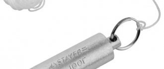
UShS-3 allows you to quickly determine the diameter of the electrodes or welding wire directly at the work site.
The UShS-3 welder template is included in most VIK kits.
UShS-3, made of high quality steel and undergoes a special anti-corrosion galvanic coating to improve the wear resistance of the template
All measuring scales on the UShS-3 template are produced using high-precision laser engraving, which increases the service life of the product.
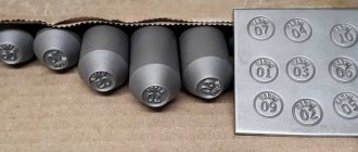
Each template is marked with a unique serial number.
After leaving production, each product (welder template UShS-3) undergoes initial/factory calibration.
SPECIFICATIONS
The general view of the template is shown in the figure:
1 - base, 2 - slider, 3 - pointer, 4-axis, A, B, C - installation planes, L - end face, M - longitudinal edge of the ruler with scale E for measuring the values of bluntness and seam width, G - scale for measuring the height of the reinforcement of the seam, K - risk index for making a report on the scale D, D - scale for measuring bevel angles of edges, F - grooves for measuring the diameters of electrodes, wires, I - scale for measuring the size of the gap.
The range of measuring the depth of defects (dents, gouges), the depth of cutting the seam to the root layer, the excess of edges (D scale) is from 0 to 15 mm.
The range for measuring the height of the seam reinforcement (scale D) is from 0 to 5 mm.
The range of measurement of bluntness and seam width (scale E) is from 0 to 50 mm.
The range of measurement of gap values (I scale) is from 0.5 to 4 mm.
Measuring range of edge bevel angles (D scale) from 0 to 45 degrees.
Nominal values of the diameters of the electrodes measured by the template (grooves G): 1; 1.2; 2; 2.5; 3; 3.25; 4; 5 mm.
Scale division prices: G and E - 1 mm, I - 0.5 mm, D - 0.5 degrees.
Limits of permissible deviations of groove width W, mm: upper value: for grooves up to 3 mm +0.1; for grooves 3 and 3.25 mm +0.12; for grooves over 3.25 mm +0.3.
The deviation of the positions of the scale strokes from the actual values is ±0.5 mm.
Deviations of the positions of the scale strokes And from the actual values of the slider thickness are ±0.25 mm.
Deviations of the positions of scale strokes D from the actual values of the angle between surfaces B and C are ±2.5 degrees.
Deviations from the nominal value of the distance between any stroke and the beginning of the scale E (the beginning of the scale must coincide with the plane L) ±0.25 mm.
Overall dimensions of UShS-3 are no more than 130×50×16 mm.
Weight no more than 0.16 kg.
Average time between failures is at least 55,000 cycles.
Average service life is at least 1 year.
Note: failure is understood as an event consisting of a loss of specified accuracy or performance, the restoration of which requires repair. A conditional cycle means moving the engine twice at an angle of at least 45 degrees.
What is a Welder Template. Its main types
Over the long history of using metal welding technology, four types of measuring devices have been created and brought to the maximum level of convenience and ease of use:
- USHK-1. Stands for “Universal Krasnovsky Template”.
- UShS-2. Often called "Cathetometer".
- UShS-3.
- UShS-4.
UShK-1
It is the simplest of the entire line. It is a drop-shaped metal plate. Two measuring scales are engraved on it and highlighted with dark wear-resistant paint.
UShK-1 allows you to measure the gap between the parts being connected, as well as three types of welding seams:
- overlap;
- T-bar;
- butt.
UShS-2
It is often called a cathetometer. As you can guess from this, it is used to determine the size of the legs of fillet welds. This is done by gradually selecting the desired angle from maximum to minimum (in this case from 14 to 4 mm ).
Externally, UShS-2 looks like three small metal parts fastened with a ring. On each of the plates there are two shaped cutouts - repeating the legs of the corresponding size (there are digital markings). The measurement is carried out by sequentially applying the plates with the cutout to the seam (perpendicularly).
The leg size is considered found when the gap between the cutout in the plate and the seam itself is minimal. Of course, it is limited - it does not cover all possible sizes of the fillet weld leg.
UShS-3
It is the most common. Can quickly control the quality and magnitude of connection defects:
- exceeding edges;
- nicks;
- bevel angles;
- gaps;
- dullness.
UShS-3 allows you to control eleven characteristics of welds and parts connected by them:
- Bevel of welded edges of parts.
- Gaps between the edges of parts.
- Size of defects.
- Convex.
- Concavity.
- Size of butt reinforcement.
- The amount of dullness.
- Seam width.
- Edge shift. By shift here we mean the difference in the level of location of the planes of the welded parts in the butt joint.
- Undercut the base of the seam. This is a discrepancy between the actual size of its leg and the planned one. It can reach up to 5 mm. This is usually caused by an excessively high operating voltage of the electric arc or an electrode that is too thick. This defect reduces the mechanical strength of the connection. It can be corrected only by carefully adding a thread stitch.
- Depth of defects. This is the distance between the defect inside the joint and its surface. The measurement range of this USS is wide enough for industrial practice. It ranges from 0 to 45º and from 0 to 50 mm. The permissible error does not exceed 0.5 mm.
UShS-4
It is the newest in origin. It partially repeats the structurally universal template of the UShS-3 welder, but has a number of improvements. For example, the Marshak-Usherov device is integrated into it. This simplifies many measuring operations.
- There is a more modern analogue of the Marshak-Usherov device - INOX or SELTOR. He is able to measure gaps before welding, the height of the weld bead, the leg of the fillet weld, and the convexity of its root. The measurement range has a limit of 20 mm .
DEVICE AND PRINCIPLE OF OPERATION
The welder's template UShS-3 consists (see figure "General view of UShS-3") from a base 1, on which, using axis 4, a slider 2 is installed with a pointer 3 fixedly fixed on it. On the front surface of the base 1 there are scales that allow you to measure the following weld elements:
G - depth of defects, depth of cutting to the root layer, excess of edges, height of weld reinforcement;
D - edge bevel angle;
E is the amount of dullness of the seam.
The engine 2 is made in the form of a plate, one end of which is made in the form of a wedge. On the front surface of the wedge part of the engine there is a scale I, and the scale numbers correspond to the thickness of the engine in a given section (thickness varies from 0.5 - 4 mm). This profile of the engine allows you to measure the gap between the parts being welded using a scale. At the wedge end of the slider there is a mark K, which is an index for the G scale. The grooves allow you to control the diameter of the electrodes and wire used.
The operating principle of the welder template UShS-3 is mechanical.
How to work with uss-3
Structurally, it consists of three parts:
- Base , with measuring scales printed on it.
- The engine is a rectangular strip of metal. It also has measuring marks and scales. It is connected to the base by a special axis.
- Pointer - has a pointed tip, attached to the slider in a certain place.
The measuring device must be protected from shock, corrosion, and chemical contamination. Before work, you need to check its integrity, the absence of bends, dents, abrasions or damage to the measuring scales.
Nine types of measurements can be carried out by the universal welder template UShS-3. Let's look at how to use it in detail for each type:
- Blurring the edges of parts. The device is applied to the edge, its length is measured using a scale at its base.
- Seam width. The UShS is located on the part - the width is determined by the scale located at its base.
- Angle of cutting edges of parts. In this case, it is placed on the surface of the part upside down. The engine is lowered until it comes into contact with the plane of the edge. The values are read from a scale around the axis of rotation of the engine. With the template in this inverted position, it is on its right side.
- The height of reinforcement of seams (both butt and corner). It is placed on the surface of the part and the slider is carefully lowered until its pointer touches the highest part of the weld. Readings are taken from the right scale.
- Displacement of the edges of parts when they are connected. To do this, place the device with its left base strictly on one of the parts. It’s more convenient to use the same one that is located to the left of the person measuring. The engine is carefully lowered down until it touches the surface of another part. Measurements are read from the scale on the far right.
- Recesses or undercuts between seam beads. It is placed with its base on the part, the slider is lowered down until its pointer comes into contact with the undercut or recess. Its value is read from the scale located on the right side of the device.
- The amount of convexity or concavity of seam undercuts. The UShS is placed on the base of the part. Then lower the slider down until its pointer touches the maximum point of convexity or concavity. The values are read from the measuring scale on the far right.
- The gap between the parts to be connected. The wedge-shaped part of the slider is placed in the space being measured, and the values are read from the corresponding scale.
- Diameter of the electrodes used. This is done by simply attaching electrodes to rectangular grooves on the upper plane of the base of the device.
- For whatever types of measurements the universal welder template UShS-3 is used (how to use it in each specific case was previously discussed in detail), it should always be positioned strictly perpendicular to the surfaces of the connected parts.
OPERATING PROCEDURE
Before starting work, it is necessary to rinse the template in gasoline in accordance with GOST 1012–72 and wipe with a clean cloth.
Measurements are carried out as follows:
To control the depth of defects (dents, nicks), the excess of edges, the depth of the joint to the root layer and the height of the reinforcement of the seam, place the template on the forming surface of the product with plane A. Rotate the slider 2 around axis 4 until the end of the pointer 3 touches the measured surface (dent surface , seam edges, etc.). Create a report on the G scale using the K mark.
Check the bluntness and width of the seam using the E scale, using it as a measuring ruler.
To control the size of the gap between the parts being welded, insert the wedge part of the engine 2 into the controlled gap until it stops. Take a report on the I scale.
To control the bevel angles of the edges, install the UShS-3 template with plane B on the formative surface of the product, turn slider 2 until plane B of the slider aligns with the surface being measured. Take a report on the D scale of the base, using plane B of the engine as an index.
To determine the diameter of the electrodes (electrode wire), it is inserted into the grooves of the template, using the grooves as staple gauges.
Modification UShS-3T
The UShS-3T modification is designed to solve particularly critical control tasks and has a linear measurement error on the B, V and D scales of no more than ±0.10 mm. Together with the UShS-4T modification, they are the only models of welder templates presented on the Russian market that fully meet the requirements of the governing documents of Transneft PJSC, namely:
- Clause 8.1.7.3 RD 25.160.10-KTN-016-15, as well as clause 5.2.4 OTT-75.180.00-KTN-046-12, according to which only verified products can be used for non-destructive testing at Transneft PJSC facilities measuring instruments.
- Clause 8.1.7.5 RD 25.160.10-KTN-016-15, which sets the limits of permissible error for visual and measuring instruments. The measurement error of the linear dimensions of UShS-3T and UShS-4T does not exceed the values given in Table 8.1 of this paragraph.
| Range of measured value, mm | Measurement error, mm |
| From 0 to 10 incl. | 0,1 |
| From 10 to 100 incl. | 0,5 |
| Over 100 | 1 |
STORAGE AND MAINTENANCE RULES
Templates must be stored in a dry and clean room, storage category 2 according to GOS 15 150−69.
When storing templates for more than 24 months from the time of their preservation, they must be preserved in accordance with GOST 9.014−78.
The conditions for transporting templates in terms of exposure to climatic factors must comply with group 8 according to GOST 15 150–69. Packed templates can be transported by all types of covered transport.
Ushs 4 universal welder template instructions
A welder's template is a tool that allows a worker to control the geometric parameters of a weld, and also, in some cases, check the preparation of edges for welding and other characteristics.
Template measurements are a visual method that is part of any welder's job. It is necessary not only to weld the part, but also to check the size of the leg and the absence of defects (lack of penetration, undercut, etc.). In practice, welders rarely use templates, since professionals in their field usually determine all the necessary characteristics of a seam without a special measuring tool. However, the template will be a useful thing for novice welders to understand the basics of welding and acquire skills that will later allow a person to become a specialist who has knowledge and understanding of basic issues, and not just poking an electrode into the metal. The template can be useful for students of vocational schools, quality control department employees, it may be required for certification, and the tool can also be used by a wide range of interested parties (again, for educational purposes).
Welder templates differ from each other both in appearance and have functional differences. Let's look at some of them in more detail.