Laboratory power supply based on a Simple and affordable power supply
In this article I would like to talk about my laboratory power supply, which was based on the “Simple and Affordable Power Supply” scheme. There are quite a few options for this device, the authors are constantly adding something, making changes, at the time when I started collecting, the latest version was v 13. However, I slightly changed the scheme, in my favor, because I planned to use a power supply for high currents and wanted to add a circuit for switching the transformer windings. Here is the original diagram:
In my version, I removed the “Overload indicator” on DA 1.3 and the “Current meter circuit” on DA 1.4, etc. Now two op-amps are free, I decided to assemble a “Transformer Winding Switching Circuit” using them, but more on that later. Because of this, the +12V stabilization circuit for the op-amp chip was changed, a separate power supply with a 7812 stabilizer was used. I also added power transistors, instead of one 2N3055 I installed a pair of 2SC5200. The maximum output current is now 5.6A. Here is my version of the scheme:
As a result, my version regulates the voltage from 0 to 25V and can limit the maximum current at a level from 0.01A to 5.6A. To final configure the circuit, you need to set the maximum voltage with resistor R13 and select resistors R14 and R16 for the maximum. and min. current accordingly.
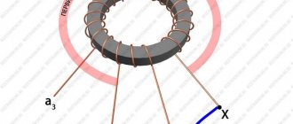
Transformer winding control
There are cases when you need to connect some kind of low-voltage load to the LPS, but with a fairly large current, for example 5V at a current of 5A. Then it turns out that several tens of volts will drop across the power transistors. For example, after the diode bridge and the capacitor in the filter we have 30V, but at the output of the LBP there is only 5V, which means 25V will drop across the transistor, and this at a current of 5A, it turns out that the poor transistor must somehow turn 125W into heat. One powerful transistor cannot do this; a thermal breakdown will simply occur and it will fail, and it will be hard for two. In this case, a circuit was invented that switches the transformer windings depending on the output voltage of the LBP. For example, if you need 5V, then why supply 30V to the LBP?
The winding switching diagram is shown below:
In my case, the LBP itself and the “switching circuit” are assembled on one board. Switching of windings occurs at output voltages of 12V and 18V. Setting up the circuit comes down to setting the required voltages with variable resistors. Resistor R2 sets the division of the output voltage by 10, i.e. if the LBP output is 25V, then the middle pin R2 (slider) should be 2.5V. Next, we set the relay response thresholds. For example, at 12V, the first relay is triggered, which means that on the 2nd leg of the microcircuit you need to set 1.2V, respectively, at 18V on the 6th leg we set 1.8V. Later it will be possible to replace the variable resistors R3 and R5 with two constant ones, soldering them as a voltage divider.
Cooling
Experimental versions of aluminum curtain rods were assembled as radiators; the profiles are screwed to an aluminum plate (I admit, I would like it to be thicker) and naturally coated with thermal paste. The efficiency of such radiators is quite good. The top cover of the case has holes for cooling.
Ampere-voltmeters
A fairly well-known circuit on a specialized MS ICL7107 was used as a voltage and current meter. I assembled according to this scheme:
Separate meals
To power the display and LM324 microcircuits, the LBP uses a separate transformer and stabilizers +5V and +12V.
About the building
The basis for the body was a piece of fiberglass, about 6-7 mm thick. Everything was assembled on it, then the front panel with all the controls and displays and the rear panel with fans and a power connector were screwed on. And on top there is a U-shaped lid covered with blue self-adhesive.
I used TN 60 transformers. They have quite powerful 6.3V windings. Current up to 7A. The weight of this device is about 10 kg.
Diode bridges of the KVRS series, 35-amp, also mounted on a common radiator with power transistors.
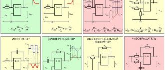
Operating principle of the op-amp
We supply some signal to the amplifier through the inputs, designated here by the symbol We (+) the so-called non-inverting input and / or We (-) the so-called inverting input. He may even have very little tension. The difference in input voltage is called differential voltage.
This amplifier is a kind of comparator - it will compare both signals to each other and behave differently depending on which signal is stronger:
We (+) > We (-) => Wy ~ Upit - Uwo
If we apply a higher voltage to the non-inverting input We (+) than to the inverting input We (-), the output will be close to the voltage Up supplied to the amplifier, minus the voltage drop across the amplifier Uwo.
We (+) < We (-) => Wy ~ 0 V
If we apply a lower voltage to the input of the non-inverting We (+) pin than to the input of the inverting We (-) pin, the output will be close to zero.
We (+) = We (-) => Wy ~ 0 V
If we apply the same signal to both inputs (called a non-differential signal in this case), the output voltage will be close to zero.
The operational amplifier with which we will conduct tests is designated LM358 (this is probably the most common op-amp chip). According to the documentation, this is a dual voltage amplifier (that is, two amplifiers in one package), so it has eight pins:
On the left is the LM358 operational amplifier; On the right is a diagram of its contacts
Pin 8 (supply voltage) and pin 4 (ground) are common to both amplifiers. The remaining legs are separate:
- the first amplifier consists of legs: 3 (We (+)), 2 (We (-)), 1 (output).
- the second amplifier consists of legs: 5 (We (+)), 6 (We (-)), 7 (output)
If you look closely, you will notice a small indentation on one side of the case. In the diagram in the note, instead of an indentation next to the number 1, there is a black dot. This is the standard way to mark the front of a chip. The legs are always numbered sequentially, starting from the notch (or point) counterclockwise.
LM358 operational amplifier with key markings
Let's check what it looks like in practice - we'll assemble a breadboard. The supply voltage is 6 V. A 220 Ohm resistor is selected for the yellow-green LED. Potentiometer P1 10 kOhm.
Attention! Before connecting the power supply to the circuit on the board, make sure that the op-amp is connected correctly, otherwise you may damage it.
Option 1 . Resistor R1 and LED D1 (yellow) are connected between the positive of the power supply and the output of the operational amplifier; The non-inverting input We (+) (the third pin of the amplifier) is also connected to the power positive.
Circuit consisting of power supply B1, operational amplifier LM358, resistor R1, potentiometer P1 and diode D1
The voltage at the We (+) input (pin 3) is higher than the voltage at the We (-) input (pin 2), so at the amplifier output (pin 1) we get a voltage close to the supply voltage, minus the voltage drop across the amplifier. The potential difference between B1's power supply and the op-amp output will be too low to power the LED, so it will remain off.
Option 2 . Resistor R1 and LED R1 (yellow in my case) are connected between the “plus” of the power supply and the output of the operational amplifier; The non-inverting We(+) input (third pin of the amplifier) is connected to ground.
The voltage at the We (+) input (pin 3) is lower than the voltage at the We (-) input (pin 2), so the amplifier output (pin 1) will be close to 0 V. The potential difference between power supply B1 and the op amp output will be enough to power supply to the LED so it will glow.
Option 3 . Resistor R1 and LED D1 (now green) are connected between the op-amp output and ground; The non-inverting input We (+) (the third output pin of the amplifier) is connected to the “plus” of the power supply.
The voltage at the We (+) input (pin 3) is higher than the voltage at the We (-) input (pin 2), so at the amplifier output (pin 1) we get a voltage close to the supply voltage minus the voltage drop across the amplifier. The potential difference between the op amp output and ground will be enough to power the LED so it will light up.
Option 4 . Resistor R1 and LED D1 (green) are connected between the op-amp output and ground; The non-inverting We(+) input (third pin of the amplifier) is connected to ground.
The voltage at the We (+) input (pin 3) is lower than the voltage at the We (-) input (pin 2), so the amplifier output (pin 1) will be close to 0 V. No potential difference between the op amp output and ground will prevent the LED from turning on , so it will remain off.
The results of the experiments are collected in the table below:
The results of the experiment - the effect of connecting We (+) - the third leg of the amplifier and the glow of the LED
Is the above circuit true for all op amps? No. Let's take, for example, another very similar op-amp, the LM393. It can only conduct electricity from a point in the circuit with a higher potential (similar to lines 1 and 2 in the table). It does not conduct current from the amplifier output to a point in the circuit at a lower voltage potential, such as ground (positions 3 and 4 in the table). In other words, if we were to use the LM393 amplifier for the experiment we just ran, the green LED would not light up regardless of the input signals. Why is this happening? Here we take a closer look at the internal structure of both amplifiers:
Diagram of the internal structure of operational amplifiers: a) LM358; b) LM393
The diagram on the left (a) shows the internal structure of the LM358 amplifier, and the diagram on the right (b) shows the LM393. Both schemes are complex, so we won’t go into details. Let's focus only on the transistors placed in front of the output (labeled OUT or OUTPUT). The LM358 has two transistors right before the output that conduct electricity in different directions (marked with a red circle). The LM393 has only one transistor just before the output (also in the red circle), which prevents current from the amplifier from flowing through the output to ground (or to a lower potential part of the circuit).
The operational amplifier is adapted to work with an external negative feedback circuit. The fact is that part of the output signal can be fed back to the input or vice versa from the input to the output of the amplifier. There can be several configurations using an op-amp and a feedback amplifier (for example, an adding, subtracting, integrating, and differentiating amplifier), but here we will consider only two of the simplest and most popular of them - non-inverting and inverting.
Simple and affordable power supply 0..50V
I would like to present to the reader a wonderful circuit of a laboratory power supply (LBP) with stabilized voltage regulation 0..50V and current regulation up to 1.5A.
The development of a simple and affordable power supply (PDBP 0...50V) was carried out on the forum of the Soldering Iron website on the initiative of a user named Olegrmz. At the time of writing this article, the forum thread contained about 500 pages of discussion of this scheme and approximately 18 of its variants. All options are working with their own characteristics. The most stable and popular version of a simple and affordable power supply is version v16y2. This is exactly what I want to present to the reader’s attention.
The advantage of the PiDBP circuit solution, in contrast to conventional circuits based on operational amplifiers (OP-amps), is that the output voltage can reach 50V, and is not limited by the op-amp supply voltage (32V), as in the vast majority of LBP circuits.
The stability of the device and its repeatability are simply remarkable. Therefore, I recommend that the reader assemble this simple and affordable laboratory power supply for his home workshop.
Scheme of a simple and affordable power supply 0...50V (version v16y2)
The circuit consists of the following components: rectifier with filter, +12V voltage stabilizer, voltage stabilization, current stabilization, indication, control unit and overheating protection.
The rectifier consists of a step-down transformer TV1, a diode bridge VDS1 and a filter C1.
The +12V voltage stabilizer is based on the VD1 microcircuit and on the VT1 transistor. Operational amplifier DA1 is powered by a stabilized +12V voltage. This value is also used as a source of reference voltage in control units.
The control unit consists of two transistors VT2 and VT4, connected according to a compound transistor circuit to increase the gain. VT4 is the most loaded element. It dissipates a large amount of heat, proportional to the difference between the input and output voltage when load current flows through it. Transistors VT2 and VT4 are controlled by VT3.
Non-inverting amplifier
Graphic symbol of a non-inverting amplifier
The voltage applied to the We (+) input is higher than that applied to We (-), so the output signal is large because it is close to the supply voltage Upit, minus the voltage drop across the amplifier Uwo (We (+) > We (-) => Wy ~ Upit - Uwo). Part of the output signal is returned through the resistor to the We (-) input, so this signal becomes greater than the voltage at We (+), and the output voltage becomes close to 0 V (We (+) < We (-)) => Wy ~ 0 V). Due to the voltage drop at the output (and the lack of signal amplification at We (-)), the voltage at We (+) will again be greater than We (-).
In practice, a state of equilibrium is quickly established in which the output signal will be constant. Its size can be easily calculated using the formula:
Uwy = Uwe (+) x [(R1 + R2) / R1]
Let's assume that the input We (+) receives a voltage of 0.5 V, and at the output we want to get 5 times more, that is, 2.5 V. Let's substitute the data into the formula:
Uwy = Uwe (+) x [(R1 + R2) / R1]
2.5V = 0.5V x [(R1 + R2) / R1]
[(R1 + R2) / R1] = 2.5 V / 0.5 V
[(R1 + R2) / R1] = 5
The ratio of the sum of the resistances of resistors R2 and R1 to R1 should give us 5. So, let's assume that the resistance of R2 = 10 kOhm and R1 = 2.2 kOhm (the ratio of their resistances is 5.54).
Let's assemble everything on a breadboard according to the following diagram:
First of all, you need to make sure that the appropriate voltage is applied to the We (+) input. To do this, connect a voltmeter between ground and the third leg of the amplifier, and then turn the potentiometer knob until the multimeter reads 0.5 V (or as close as possible).
Now measure the voltage at the output of the amplifier, that is, between the first contact and ground. Theoretically, you should get a result close to 2.5 V. Meanwhile, the voltmeter reading is as much as 2.88 V.
Where does this difference come from? Remember, we didn't use resistors with a factor of 5.54, not 5. Let's plug the data (real data this time) into the formula again:
Uwy = Uwe (+) x [(R1 + R2) / R1]
Uwy = 0.51 V x [(2.16 kOhm + 10 kOhm) / 2.16 kOhm
Uwy = 0.51 V x 5.63
Uwy = 2.87 V
Theoretically and practically we got almost the same result - 2.87 V.
Regulated power supply with overload protection
When configuring all kinds of radio-electronic devices, it often happens that you need a power supply that has the function of smoothly adjusting both the output voltage and the overload current value.
Power supply overload protection
In most simple units, the power supply is protected from overload only when the maximum load current is exceeded. Such electronic protection is primarily intended for the power supply itself, and not for the load connected to it.
For reliable operation of both the power supply and the electronic device connected to it, it is desirable to be able to change the current protection threshold within wide limits, and when the protection is triggered, the connected load must be de-energized.
The circuit presented in this article is another version of a laboratory power supply, which allows for smooth adjustment of all the parameters listed above.