11/17/2021 Author: VT-METALL
From this material you will learn:
- Basic welding mode parameters
- Ratio of current to electrode thickness during welding
- Selecting the electrode diameter when welding metals
- Arc Length Options
- Selecting polarity and current type
- Tilt of the electrode and the workpiece during welding
- Parameters of gas shielded welding mode
- Effect of welding speed
Welding modes and parameters change when performing welding work depending on the type of workpiece, thickness and properties of the metal. If the recommended standards are observed, the weld will be of high quality and the connection itself will be reliable.
Welding parameters are easy to follow; for certain types, ready-made tables have been developed that take into account the main factors. It is enough to study them once and then cook them like clockwork. What are these parameters and what is their difference, read in our material.
Basic welding mode parameters
Welding mode refers to the main characteristics of the welding process, due to which welded joints of specified parameters, shapes and sizes are obtained. In this case, these characteristics can be: current density in the electrode, strength of the cooking current, speed of the cooking process, grade and granulation of flux, arc voltage, shielding gas consumption.
VT-metall offers services:
In order to determine which welding mode is required, it is necessary to determine the thickness and type of structure, as well as the composition of the metals. Based on the data received, the desired mode is set. There are two groups of factors on which the quality of welding depends: primary and secondary.
Three main types of connections
GOST 5264-80 describes all types of standard connections used in production. If joints are used that are not described in the list, then in the accompanying documentation (drawing) the designer makes a footnote indicating the parameters of the seam.
Connection types:
- Butt welding – used for welding sheets and flat parts. There are: with flanged edges, with or without cutting, on a removable or permanent lining.
- Angular - for connecting elements in which the edge of one of them abuts the plane of the second at an angle other than 0 degrees.
- Overlapping - used when installing parts, with the side of one superimposed on the plane of the other.
Types of welded joints
The main purpose of creating a permanent joint is to ensure sufficient strength for the operation of the metal structure.
Ratio of current to electrode thickness during welding
Electrodes are selected depending on the thickness of the seam being welded and the welding method. They can be in a 1:1 ratio. So, for a seam with a thickness of 3-4 mm, an electrode measuring 3 mm is suitable. Multi-profile parts are welded gradually. They usually start with a 4 mm electrode.
If you do not make a calculation at the beginning of work and take an electrode with a smaller diameter, then the seam will not be filled completely, which will lead to a weak connection.
When choosing an electrode, you need to refer to the tables to determine the current strength. For a diameter of 3 mm, the required current is 65–100 A. If you have a vertical seam, then the minimum value of its diameter should be at least 4 mm. It should be remembered that when horizontal welding, the current must be reduced by 15–20%.
The welding current value is calculated by the formula:
I = K × d,
Where:
I – welding current strength in amperes;
K – coefficient;
d – electrode diameter in millimeters.
When vertical welding, the current is reduced by 10%; in ceiling seams, it is reduced to 20% of the obtained value. From this table you can select the coefficient K:
| Electrode diameter, mm | K, A/mm |
| 1-2 | 25–30 |
| 3-4 | 35–40 |
| 5-6 | 45–50 |
Manual arc welding technology
Manual arc welding is performed using welding electrodes, which are manually fed into the arc and moved along the workpiece. During welding with a coated metal electrode, an arc burns between the electrode rod and the base metal. The electrode rod melts and the molten metal flows in drops into the metal bath. Together with the rod, the electrode coating melts, forming a protective gas atmosphere around the arc and a liquid slag bath on the surface of the molten metal. The metal and slag pools together form the weld pool. As the arc moves, the weld pool hardens and a weld seam is formed. Liquid slag after cooling forms a solid slag crust.
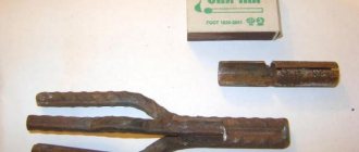
Electrodes for manual welding are rods with coatings applied to them. The rod is made from high quality welding wire. Welding wire of all brands, depending on the composition, is divided into three groups: low-carbon, alloyed and high-alloyed.
Manual welding is convenient when making short and curved seams in any spatial positions (Fig. 1) - bottom, vertical, horizontal, ceiling, when applying seams in hard-to-reach places, as well as during installation work and assembling structures of complex shapes. Manual welding produces good quality welds, but has lower productivity, for example, compared to automatic submerged arc welding.
Rice. 1. Types of welds
The performance of the process is mainly determined by the welding current. However, the current during manual welding with coated electrodes is limited, since increasing the current above the recommended value leads to heating of the electrode rod, peeling of the coating, severe spattering and waste of molten metal.
Mode selection. The welding mode is understood as a set of controlled parameters that determine the welding conditions.
The diameter of the electrode is selected depending on the thickness of the metal, the leg of the weld, and the position of the seam in space.
The approximate relationship between the metal thickness S and the electrode diameter dе when welding in the lower position of the seam is:
| Metal thickness, S, mm | 1—2 | 3—5 | 4—10 | 12—24 | 30—60 |
| Electrode diameter, de, mm | 2—3 | 3—4 | 4—5 | 5—6 | 6—8 |
The current strength mainly depends on the diameter of the electrode, but also depends on the length of its working part, the composition of the coating, and its position in the welding space.
The higher the current, the greater the productivity, i.e., the greater the amount of deposited metal:
Q = αнIсвt ,
where Q is the amount of deposited metal; αн — deposition coefficient, g/(Ah);
Iw—welding current, A; t — time, h.
However, if the current is excessive for a given electrode diameter, the electrode quickly overheats beyond the permissible limit. This leads to a decrease in seam quality and increased spattering. If the current is insufficient, the arc is unstable, often breaks, and the weld may lack fusion. The current value can be approximately determined using the following formulas:
when welding structural steels for electrodes with a diameter of 3-6 mm:
Id = (20 + 6de)de; for electrodes with a diameter of less than 3 mm:
Id = 30dе,
where de is the diameter of the electrode, mm.
Welding seams in vertical and overhead positions is usually performed with electrodes with a diameter of no more than 4 mm. In this case, the current strength should be 10-20% lower than for welding in the lower position. The arc voltage varies in a relatively narrow range of 16-30 V.
Welding technique. An arc is a powerful, stable discharge of electricity in an ionized atmosphere of gases and metal vapors. Ionization of the arc gap occurs during arc ignition and is continuously maintained during its combustion. The arc ignition process in most cases includes three stages: short circuit of the electrode to the workpiece, withdrawal of the electrode and the occurrence of a stable arc discharge.
The arc can be excited in two ways: by touching the end of the electrode to the workpiece and moving it away from the workpiece perpendicularly upward at a distance of 3-4 mm (Fig. 2), or by quickly lateral movement of the electrode to the workpiece being welded and moving the electrode away from the workpiece (“striking” the electrode on the workpiece , like lighting a match). The contact of the electrode with the product must be short-term, otherwise it will be welded to the product. The second method is more convenient, but is unacceptable in narrow and inconvenient places.
Rice. 2. Arc ignition methods : a - lateral movement; b - touching the electrode
During the welding process, it is necessary to maintain a certain arc length, which depends on the brand and diameter of the electrode. Approximately normal arc length should be within
Ld = (0.5 - 1.1)de,
where Ld is the length of the arc, mm; de—electrode diameter, mm.
The length of the arc significantly affects the quality of the weld. A short arc burns steadily and ensures a high-quality weld, since the molten metal quickly passes through the arc gap and is less subject to oxidation and nitriding. In addition, long-arc welding with basic-type coated electrodes leads to porosity of the weld metal. To correctly form a seam when welding with a consumable electrode, it is necessary to hold the electrode inclined in relation to the surface of the metal being welded, at an angle of 15-20° from the vertical line. By changing the angle of inclination of the electrode, you can regulate the depth of fusion of the base metal and influence the cooling rate of the weld pool. In Fig. Figure 3 shows the effect of the inclination of the electrode and the inclination of the welded product on the depth of penetration of the base metal.
Rice. 3. The influence of the inclination of the electrode and the inclination of the welded product on the depth of penetration of the base metal : a - forward angle welding; b - backward angle welding; c - welding with a vertical electrode downhill; d - welding with a vertical electrode on the rise; d - welding with a vertical electrode on a horizontal surface
In addition to the arc length, the quality of the weld is also affected by the magnitude of the welding current, voltage and welding pace. The appearance of the resulting weld when deviating from normal conditions is shown in Fig. 4.
Rice. 4. Dependence of the weld on voltage, current and welding rate
During the welding process, the electrode moves in three directions.
- The first movement is translational, in the direction of the electrode axis. This movement maintains a constant (within certain limits) arc length depending on the melting rate of the electrode.
- The second movement is the movement of the electrode along the axis of formation of the weld bead. The speed of this movement is set depending on the current, the diameter of the electrode, the speed of its melting, the type of seam and other factors. In the absence of transverse movements of the electrode, a so-called thread roller is obtained, 2-3 mm wider than the diameter of the electrode, or a narrow seam with a width of e = 1.5 dе.
- The third movement is to move the electrode across the seam to create a seam wider than the thread bead, the so-called widened bead.
The transverse oscillatory movements of the end of the electrode are determined by the shape of the groove, the size and position of the seam, the properties of the material being welded, and the skill of the welder. Wide seams (e = (1.5 – 5)dе) are obtained using transverse vibrations shown in Fig. 5. Using the example of these basic oscillatory movements in table. 1 shows the movements of the electrode during various types of welding.
Rice. 5. Scheme of movement of the end of the electrode during manual electric arc welding
When welding thin sheets, apply a narrow bead (0.8-1.5 width of the electrode diameter) without transverse vibrations. In other cases (when welding thick sheets), widened beads are used. Oscillatory movements improve heating of the weld edges, slow down the cooling of the deposited metal pool, ensure a uniform weld and eliminate lack of penetration of its root.
Table 1. Examples of electrode movement for various types of welding
| Name of movements | Movement pattern _________________________________ | Purpose |
| Reciprocating motion in one plane | Used to obtain a weld bead with high-performance electrodes in all positions and for all types of joints | |
| Cyclic movement of the electrode | Used for root welding of fillet welds and V-shaped grooves with high-performance electrodes | |
| Straight-line zigzag movement of the electrode in the vertical plane | Used with all types of electrodes for filling vertical corner and V-groove seams, sometimes used for facing seams. With low-hydrogen electrodes used for root welding of fillet welds and V-shaped grooves | |
| Triangular electrode movement | Used for facing seams. With low-hydrogen electrodes it is used for welding the root of fillet welds and V-shaped grooves | |
| Reciprocating motion with vertical displacement between passes | Suitable for use with all types of electrodes for filling vertical corner and V-shaped joints. At the end of the horizontal movement, on both edges, the electrode has a fixed delay, then moves upward slightly | |
| Movement with overlap and slight rocking of the electrode around the weld pool | Used with all types of electrodes for welding ceiling seams, sometimes during cyclic movement the crater overlaps | |
| Straight-line zigzag movement of the electrode in the horizontal plane | Can be used with all types of electrodes in wide V-shaped grooves in the down position |
Butt welding without cutting edges is carried out mainly by through penetration on one side of the seam. In these cases, it is recommended to use pads (steel, copper). Sometimes, when possible, the seam is welded with a narrow bead on the reverse side.
Parts for welding are assembled in fixtures, most often with tacks. The cross-section of the tack weld is approximately 1/3 of the cross-section of the main weld, its length is 30-50 mm. Fillet welds are welded “in a corner” or “in a boat” (Fig. 6).
Rice. 6. Position of the electrode and the product when making fillet welds : a - welding in a symmetrical “boat”, b - in an asymmetrical “boat”, c - “in the corner” with an inclined electrode, d - with melting of the edges
When forming a fillet weld (Fig. 6, a, b, c), the electrode is placed at an angle of 45° to the surface of the part. Using increased current values, in order to avoid lack of weld penetration, both surfaces to be welded are tilted to the horizontal plane at an angle of 45° (boat welding, Fig. 6, a). When the surfaces to be welded are tilted at an angle of 30° or 60° - into an asymmetrical boat.
When welding “in the corner”, assembly is simpler, a large gap between the parts being welded is allowed (up to 3 mm), but the welding technique is more complex, defects such as undercuts and sagging are possible, productivity is lower, since it is necessary to weld seams of a small section in one pass (leg < 8 mm) and use multilayer welding. Boat welding is more productive, allows for larger seam legs in one pass, but requires more careful assembly.
When butt welding a seam with a V-shaped groove (Fig. 7, a), the arc is ignited near the bevel of the edges and a metal bead is deposited. Depending on the thickness of the sheet and the diameter of the electrode, the seam is performed in one or several passes.
When multilayer welding, each layer is thoroughly cleaned. The number of layers is determined based on the diameter of the electrode. The layer thickness is (0.8 ÷ 1.2)del.
Welding X-shaped seams (Fig. 7, b) in order to reduce deformation is carried out by alternately applying layers on both sides of the groove.
Rice. 7. Butt welding with edge preparation : a - diagram of the application of metal beads with a V-shaped edge preparation; b - butt welding with double-sided cutting of edges.
The assembly of parts in preparation for welding, cutting of metal edges and gaps between parts during butt welding, according to GOST, are shown in the figures in table. 2, as well as in Fig. 8-11.
Table 2. Main types and sizes of structural elements of the seam
| Type of welds according to GOST | Name of welded joint | Type of structural elements | Welded joint | Size of structural elements | ||
| — | With flange | — | S=1÷3 | |||
| C2 | Butt joint without bevel edges, double-sided | S=S1 | b | a | ||
| 3÷3,5 | 8±4 | 1+0,5-1,0 | ||||
| 4÷4,5 | ||||||
| 5÷5,5 | 9±4 | |||||
| 6÷8 | 2+1,5-1,0 | |||||
| h=2÷3 | ||||||
| C3 | Butt joint without bevel edges, one-sided | |||||
| C8 | Butt V-shaped with bevel of two edges, double-sided | S=S1 | b | S2 | ||
| 3÷8 | S+11 | 1±1 | ||||
| 9÷14 | S+13 | 2+1,0-2,0 | ||||
| 15÷21 | S+15 | |||||
| C9 | Butt V-shaped with bevel of two edges, one-sided | 22÷26 | S+16 | |||
| b1=10±4; h=3÷4 | ||||||
| C11 | Butt V-shaped with a curved bevel of two edges, double-sided | S | b | h | ||
| 20÷23 | S+9 | 0+5 | ||||
| 24÷29 | S+7 | |||||
| 30÷33 | S+4 | |||||
| 34÷41 | S | |||||
| 42÷49 | S-3 | |||||
| 50÷55 | S-7 | |||||
| 56÷60 | S-12 | |||||
| b1=10±4 | ||||||
| C15 | Butt X-shaped with two bevels of two edges side-by-side symmetrical | S | b | h | ||
| 12÷17 | S+3 | 3 | ||||
| 18÷29 | S+1 | 4 | ||||
| 30÷44 | S-3 | |||||
| 42÷50 | S-8 | |||||
| 51÷60 | S-11 | 5 | ||||
| Type of welds according to GOST | Name of welded joint | Type of structural elements | Welded joint | Size of structural elements | ||
| C17 | Butt X-shaped with two curved bevels of two edges, double-sided | S | b | h | ||
| 30÷35 | S-3 | 4 | ||||
| 36÷41 | S-7 | |||||
| 42÷51 | S-12 | 5 | ||||
| 52÷60 | S-24 | |||||
| U4 | Corner without bevel edges, double-sided | S=2÷30; S1=2÷30 | ||||
| U5 | Corner without bevel edges, one-sided | S=1÷30; S1=2÷30 | ||||
| U7 | Corner with bevel of one edge, one-sided | S | b | |||
| 4÷7 | S+11 | |||||
| 8÷11 | S+13 | |||||
| 12÷17 | S+15 | |||||
| 18÷26 | S+18 | |||||
| h=3÷4; S1≤S | ||||||
| U10 | Corner with bevel of two edges, one-sided | S | b | |||
| 12÷14 | S+12 | |||||
| 16÷21 | S+14 | |||||
| 22÷26 | S+15 | |||||
| h=4; S1=S | ||||||
| T1 | T-type without bevel edges, double-sided | S | K | |||
| 3÷6 | 3÷4 | |||||
| 7÷9 | 5 | |||||
| 10÷30 | 6÷8 | |||||
| Type of welds according to GOST | Name of welded joint | Type of structural elements | Welded joint | Size of structural elements | ||
| T8 | T-bar with bevel of one edge, double-sided | S | b | h | ||
| 4÷7 | S+9 | 3±3 | ||||
| 8÷11 | S+11 | |||||
| 12÷17 | S+13 | 4±3 | ||||
| 18÷26 | S+16 | 5±3 | ||||
| T9 | T-bar with bevel of one edge, single-sided | b1=3 | ||||
| T10 | T-bar with bevel of two edges, double-sided | S | b | h | ||
| 12÷17 | S+2 | 3±3 | ||||
| 18÷25 | S | 5±3 | ||||
| 26÷35 | S-2 | 6±3 | ||||
| 36÷47 | S-3 | 9±3 | ||||
| 48÷51 | S-4 | 11±3 | ||||
| 52÷60 | S-5 | 13±3 | ||||
| H2 | Lap without bevel edges, double-sided | S=2÷60; k=S | ||||
| H3 | Overlapping with electric rivets | S≥2; d≥2S | ||||
| H4 | Overlapping with electric rivets | S≥2; m≥2S | ||||
Butt welding of sheets of different thicknesses is shown in Fig. 8. The connection of overlapping sheets with frontal seams is shown in Fig. 9.
The connection of sheets with overlapped flank seams and reinforcement with slotted seams is shown in Fig. 10.
The butt connection of sheets with overlays is shown in Fig. 11. The overlays are welded to the sheets using frontal and flank seams (the middle projection is common to both joints).
Rice. 8. Cutting edges of sheets of different thicknesses for butt welding
Rice. 9. Joining sheets with overlapped frontal seams
Rice. 10. Joining sheets with overlapping flank seams, reinforced with slotted seams
Rice. 11. Joining sheets end-to-end with one overlay (a) and the same, with two overlays (b)
To increase the performance of welded structures and reduce internal stresses and deformations, the order of filling the seams is of great importance. The order of filling seams means both the order of filling the seam cut along the cross section and the sequence of welding along the length of the seam.
According to their length, all seams can be divided into three groups:
- short - up to 300 mm;
- medium - 300-1000 mm;
- long - over 1000 mm.
Depending on the length of the seam, the material, the requirements for accuracy and quality of welded joints, welding of such seams can be performed in various ways (Fig. 12).
Rice. 12. Welding patterns : a - pass-through; b - from the middle to the edges; c - back in a stepwise manner; g - blocks; d - cascade; e - slide; A - direction of filling the groove: (arrows indicate the direction of welding); 1-5 welding sequence in each layer
Short seams are made as a pass - from the beginning of the seam to its end. Medium-length seams are welded from the middle to the ends or back using a stepwise method. Long-length seams are made in two ways: from the middle to the edges (in a reverse stepwise manner) and scattered.
With the reverse step method, the entire seam is divided into small sections 150-200 mm long, and in each section welding is carried out in the direction opposite to the general welding direction. The length of the sections is usually from 100 to 350 mm. Depending on the number of passes (layers) required to complete the design section of the seam, single-pass (single-layer) and multi-pass (multilayer) seams are distinguished.
From a productivity point of view, the most appropriate are single-pass welds, which are usually used when welding metal of small thicknesses (up to 8-10 mm) with preliminary cutting of the edges.
Welding of connections of critical structures of large thickness (over 20-25 mm), when volumetric stresses appear and the risk of cracking increases, is carried out using special techniques: filling the seams with a “slide” or “cascade” method.
When welding “slide”, first the first layer of short length 200-300 mm is deposited into the groove of the edges, then the second layer overlaps the first and is twice as long. The third layer overlaps the second and is 200-300 mm longer than it. The layers are fused in this way until the groove is filled in a small area above the first layer. Then, from this “hill”, welding is carried out in different directions using short seams in the same way. Thus, the welding zone is in a hot state all the time, which helps prevent the occurrence of cracks. The “cascade” method is a type of slide.
When welding horizontal seams on a vertical plane (Fig. 13, a), only the top sheet is cut, the arc is excited at the bottom edge, then gradually moves to the beveled top edge.
Vertical seams are more difficult to weld due to the molten metal flowing down. To reduce the flow of metal, work is carried out with a short arc and in the direction from bottom to top (Fig. 13, b), with the exception of sheets up to 1.5 mm thick.
Welding ceiling seams (Fig. 13, c) is carried out with a very short arc, during which the electrode short circuits to the part. Electrodes with a refractory coating are used, which forms a “sleeve” around the electrodes containing a directed gas flow that holds the electrode metal.
Rice. 13. Schematic representation of the work when performing welding with various seams : a - horizontal seam on a vertical plane; b - vertical seam; c - ceiling seam. 1—3 — position of the electrode in space; 4 — electrode coating
Ensuring regulatory requirements for welding technology and techniques is the main condition for obtaining high-quality welds. Deviations of the size and shape of the weld from the design ones are most often observed in fillet welds and are associated with violation of welding conditions, improper preparation of edges for welding, uneven welding speed, as well as untimely control measurements of the seam.
735
Selecting the electrode diameter when welding metals
For a more correct choice of electrode, it is necessary to clarify the following indicators: the thickness of the product being welded, the location of the seam (horizontal, vertical, ceiling), the shape of the edges and the type of connection. The main indicator is the thickness of the metal, and other factors serve for more accurate adjustments.
In this table you can select the electrode diameter you need based on your indicators:
| Thickness of welded metal | Electrode diameter |
| 1,5 | 1,6 |
| 2 | 2 |
| 3 | 3 |
| 4-5 | 3-4 |
| 6–8 | 4 |
| 9–12 | 4-5 |
| 13–15 | 5 |
| 16–20 | 5 or more |
The root layer can be made with electrodes with a diameter of 2.5-3 mm. To do this, the edges must be cut. Ceiling seams are most often made with electrodes with a diameter of 3-3.2 mm. The tabular data is ideal for horizontal seams.
Welding of rotary pipe joints
When welding on rotators, select the pipe rotation speed (Vwr) equal to the welding speed (Vw). The welding position most convenient for forming a seam is not at the zenith, but at a point 30-35° from the vertical in the direction opposite to the direction of rotation of the pipe.
When there are no rotators or they are impractical, the welded pipe joints are turned at angles of 60-110°. This allows you to form the seam in the most convenient position - bottom.
Pipes with a diameter of more than 219 mm are welded using a reverse-step method in two full turns:
Pipes rotated 180° are welded in three steps. First, the GL and VL sections are welded in one or two layers. After this, the pipe is turned 180° and the sections of the VB and GB are welded to the full thickness.
Then the pipe is turned 180° and the remaining groove is welded in the HA and VL sections. Welding pipes with a 180° rotation can be performed by one or two welders.
Welding of pipe joints with a 90° turn is also carried out in three steps. First, weld the AVB joint area, laying one or two layers. Then the pipe is turned 90° and the entire thickness of the AGB section is welded. Finally, a reverse turn by 90° follows and welding of the remaining thickness of the pipe in the AVB section.
Welding with a joint rotation allows you to form a high-quality seam with minimal deformations and stresses, a smooth transition to the base metal, with minimal scaliness without sagging or undercuts.
Arc Length Options
In welding, arc voltage is the most important parameter that determines its length. To put it simply, this is the distance from the end of the electrode to the object. This indicator directly depends on the electrode and is presented in tables. A piece of work is considered to be of high quality if there is not a single imperfection throughout the entire seam. In this profession, experience is important; only a professional is able to follow such a subtle nuance.
We recommend articles:
- Butt welded joint: types, execution technology
- Welding arc: its properties, types, principle of operation
- Lap joint: welding for a wide range of applications
Combustion becomes stable if the arc voltage is increased. With such welding, the likelihood of air entering the seam zone increases, and the elements contained in the wire burn out, resulting in the formation of pores. The arc ignition process includes three stages: a short circuit of the electrode to the workpiece, after which the electrode is withdrawn by 3–6 mm and a stable arc discharge occurs.
Mode depending on arc voltage
Arc voltage is related to its length. Typically the voltage is set in the range of 20-36 V. It increases as the arc length increases. The length of the arc can be short, medium and long.
Arc length is the distance from the tip of the electrode to the metal being welded. To make a quality connection, you need to ensure a stable arc size. It is believed that for beginners it is easier to maintain an average arc size. It is possible to make a high-quality seam with a short arc, but this requires experience and professionalism.
Selecting polarity and current type
Welding machines are capable of converting household alternating current into direct current. It is important not to confuse the polarity. It involves connecting the part to “+” and the electrode to “-”. The specialist selects the mode parameter based on the properties of the part.
For welding cast iron parts, straight polarity is suitable. It is also suitable for medium carbon steel with a thickness of 5 mm.
When connecting low-carbon steel and thin-sheet structures, reverse polarity is chosen.
Application area
Power sources for manual arc welding allow it to be used in almost any area. More often than others, it is found in the domestic sphere, as it can operate from a standard network. The quality of the resulting seam is quite sufficient for this type of application. In addition, in almost every enterprise that works with metal, there is a place to use such technology. It is best suited for joining carbon steels.
When creating metal structures such as gates, gratings, fences, etc., this method is one of the main ones. Factories and enterprises that repair their equipment or create new ones also have welding inverters and transformers in their arsenal. It is not at all necessary that in some area they will be the only welding method, since for simple and less critical connections this inexpensive technology may be the best.
Tilt of the electrode and workpieces during welding
It is important to take into account the angle of inclination of the electrode when working with a semi-automatic machine and to correctly calculate the welding modes. In such work, the rod in relation to the seam should deviate from the norm by 10°. The depth and width of the joint depends on the location of the rods to the joint.
The connection expands, and the depth indicators decrease, provided that welding occurs at an angle forward, due to which the arc drives a wave of melt in front of itself, through which the metal is melted.
The melt will flow to the end of the cooking zone if you select the backward tilt mode. The electric arc has a direct effect on the products being connected. Due to this, the depth of penetration of the joint increases and the width of the seam decreases.
To ensure high-quality filling of the seam, it is recommended to tilt the part at an angle of 8–10°. Otherwise, the molten metal may flow down or lack of penetration will remain. When welding pipes, it is impossible to change their angle, so welding is done from top to bottom.
Basics of RDS. Advantages and disadvantages
The creation of one-piece structures using RDS is based on melting the edges of parts while simultaneously filling the weld pool with the liquid metal of the coated electrode. Protection is carried out with the participation of a coating, which, when heated, covers the working area with a film and a mixture of gases, displacing harmful impurities and oxygen.
Thanks to this, work can be carried out both indoors and outdoors. The influence of wind is minimal in contrast to welding in a shielded gas environment. Apart from the welding machine itself and electrodes, nothing is required, so quickly moving equipment around the site does not cause difficulties.
The downside is the difficulty of working with vertical and ceiling seams; in this case, the welder needs to have some experience and appropriate qualifications.
Also recognized as a negative point is low labor productivity compared to the use of semi-automatic equipment.
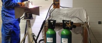
Parameters of gas shielded welding mode
The welding mode is determined depending on the diameter of the wire and the strength of the welding current. Specialists increase gas consumption to improve gas protection, reduce welding speed, and use protective screens during work.
During welding, gas is supplied to the combustion zone. It displaces air from the arc combustion zone, thereby protecting the weld pool from oxygen and nitrogen from the air. The process is divided into welding in active (CO2, H2, O2, etc.) and inert (He, Ar, Ar+He, etc.) gases.
Consumable and non-consumable electrodes can be used in welding. To a greater extent, specialists work with consumable electrodes. This method is inexpensive when welding carbon and low-alloy steels, so it occupies one of the first places in terms of production volume among mechanized fusion welding methods. When using wire:
- with a diameter of up to 1 mm, and a current from 60 to 160 A, gas flow should be up to 8 liters per minute.
- with a diameter of up to 1.2 mm, and a current strength from 100 to 250 A, gas flow should be up to 9–12 liters per minute.
- with a diameter of up to 1.4 mm, and a current strength of 120 to 320 A, gas flow should be up to 12–15 liters per minute.
- with a diameter of up to 1.6 mm, and a current strength from 249 to 380 A, gas flow should be up to 15–18 liters per minute.
- with a diameter of up to 2 mm, and a current from 280 to 450 A, gas flow should be up to 18–20 liters per minute.
This is the average gas consumption when welding with a semi-automatic machine. There are also indirect factors that can affect additional gas consumption, for example, if welding takes place outside. In this case, the gas will quickly evaporate, thereby increasing its consumption.
Don’t forget about the quality of the gas itself, because if the gas is diluted, you simply won’t be able to keep the indicators normal; there will be excess consumption in any case.
Welding current
Current has defining properties: type, polarity and strength. By type, current is divided into direct and alternating. Polarity can be direct or reverse.
Most welding machines operate on direct current. The difference between direct current and alternating current is that direct current does not change in direction or magnitude. Thus, it ensures the stability of the arc. The only disadvantage of direct current in the process of joining metals is the possibility of a magnetic blowing effect. It occurs when connecting large structures, when an extraneous magnetic field (from magnetized products) affects the magnetic field of the arc. In this case, the arc begins to “run out” beyond the area where the seam is located and combustion stability decreases sharply. This disadvantage can be combated by
- fencing the work area with special screens that protect from “extra” magnetic fields
- grounding of welded surfaces
- identify possible options for using alternating current
The advantage of working on direct current is a stable arc and the ability to select polarity. Direct polarity is also called electrode-negative, reverse polarity is also called electrode-positive. Reverse polarity occurs when the electrode is connected to the positive and the metal to the negative. With direct polarity, the opposite is true. The difference between the polarities is as follows. The laws of physics say that where the plus is connected, that element heats up more. Thus, with straight polarity, the metal product heats up more. This polarity should be used to join thick parts, since this process requires more melting of the metal to obtain a good weld. If direct polarity is used on a thin product, it will “burn” and the seam will turn out to be of poor quality. For thin metals, reverse polarity is carried out.
The amount of current is determined by the characteristics of a particular welding machine. In modern models, these indicators are indicated in the instructions. If for some reason you do not have instructions, then the current strength can be selected depending on the diameter of the electrode used. It is not allowed to use a current strength that is more suitable for a particular electrode. In this case, the electrode coating used to make the connection will be damaged and the arc will operate unstably. Using an electrode that is too large also has a bad effect on the process of joining metals: the current density decreases, the arc “runs away,” its length changes, and the weld does not turn out smooth and of high quality.