Design and principle of operation
The functioning of a forging hammer is based on the dynamic impacts of the working body - the rod, connected to the head (the striking part of the machine) and devices that control the force of impact. Other required structural elements are:
- a piston connected to a woman;
- base (fixed on a solid surface);
- bed (guides for moving units are fixed on it);
- drive equipment;
- shield fence (for operator safety);
- electrical equipment;
- compressor cylinder (for pneumatic hammers).
Early machines were either foot or hand driven. A modern forging hammer is equipped with a convenient control system that minimizes the effort of the forge worker.
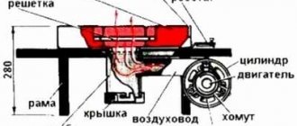
Rice. 1. Pneumatic hammer device.
(1 - working cylinder, 2 - compressor cylinder, 3 - piston, 4 - crank mechanism, 5 - woman, 6 and 7 - upper and lower strikers, 8 - cushion, 9 - air distribution mechanism, 10 - deformable workpiece)
Briefly, the device works like this:
- the workpiece is placed in the lower part of the hammer (usually the hammer);
- set the device to a certain impact frequency and set it in motion;
- after activating the hammer, the driven upper part hits the workpiece;
- the dynamic effect continues until the workpiece acquires the desired shape.
When a forging hammer operates, the reciprocating movement of the crank mechanism is converted into the same movement of the piston. This allows you to perform many operations on it.
Hand forging tool
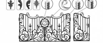
Hand forging is mainly used for repair and assembly work, as well as for the production of unique, including artistic products in small quantities.
In this regard, hand forging is currently undergoing intensive development. Depending on the type of forging, blacksmith tools are divided into tools for hand and machine forging. According to their functional purpose, all forging tools are classified into basic technological ones; supporting and control. Depending on the nature of use, the tool can be universal or specialized.
The main technological tool is a tool that directly deforms the metal and gives it the shapes and dimensions specified in the forging drawing. In turn, the main technological tool for hand forging is divided according to purpose into support, impact and backing.
1.1. The main technological tool for hand forging
Manual forging operations, such as broaching, upsetting, bending, punching and piercing holes, cutting, forge welding and straightening, are performed using a support tool, which includes anvils (Fig. 1). They are made by casting from steel grade 45L weighing 70...350 kg. The top flat part of the incus is called the face. Sometimes a steel plate up to 30...40 mm thick is welded onto the top of the face, which is called the platband. After heat treatment, the hardness of the face or casing should be 40...45 HRC.
Based on the number of conical parts called horns, three types of anvils are distinguished: hornless (GOST 11396–75), one-horned (GOST 11397–75) and two-horned (GOST 11398–75). Anvil horns are used, for example, when performing bending and forging operations of hollow forgings. On the flat part of the anvils, two through holes are usually made: a round one for punching holes in workpieces and a square one for installing a backing tool.
Rice. 1. Anvils: a – hornless; b – one-horned; c – two-horned
The lower part of the anvil - the shoe - has four legs, with which the anvil is attached to the chair using crutches or clamps. The latter is a concrete pedestal or wooden block dug into the ground to a depth of 1...1.5 m. In this case, the front surface of the anvil should be at a distance of 750...800 mm above the floor level.
Shperak (GOST 11400–75) is a small anvil (Fig. 2) with two horns weighing up to 50 kg. It is made by casting or forging from steel 45. Its casing has a hardness of 40...45 HRC. The shperak is installed in the square hole of the anvil.
Rice. 2. Shperak
Impact tools for hand forging are sledgehammers and hammers. The latter are sometimes called handbrake. A blacksmith uses a hammer both to strike and to indicate to the hammerman where to strike with a sledgehammer when processing relatively large workpieces. Hammers are made with a mass of 0.5...2 kg by forging from U7 or U8 steel.
The hammer contains two strikers, one of which is round or square, sometimes octagonal, and has a smooth striking surface with rolled edges. The other firing pin, also called the butt or toe, can be spherical, pointed with a rounded edge, or blunt. The hammer heads are hardened and then tempered.
Sledgehammers are the main tool for hand forging. They are used to strike a workpiece heated to forging temperatures; they also have two strikers and are divided into blunt (GOST 11401–75) and pointed (GOST 11402–75) (Fig. 3). The mass of the sledgehammers is 2…16 kg. Pointed sledgehammers can have transverse or longitudinal toes (backs).
To secure the handle in the sledgehammer, an oval attachment hole is provided, which expands from the middle to the edges. Sledgehammers are made by forging or stamping from steels 40, 45, 50 and U7, followed by cutting of the working surfaces.
Rice. 3. Sledgehammers: a – blunt-nosed; b and c – pointed-nosed with transverse and longitudinal hindquarters, respectively
After heat treatment of the sledgehammers, the hardness of the working layer up to 30 mm deep should be 48...52 HRC.
Forging chisels (GOST 11418–75) are made from steel U7 and 6ХС and are used for hot and cold chopping of metal (Fig. 4). The former are sharpened to an angle ≥ 60°, the latter – to an angle ≤ 50°. The blade of chisels is made straight, semicircular or shaped. Its hardness at a length of ~30 mm from the working edge is 50...56 HRC, and the hardness along the impacted part at a length of ~20 mm is 30...40 HRC.
Smoothers (Fig. 5 and 6) are used to smooth out unevenness and final finishing
Rice. 5. Ironer
Rice. 4. Forging chisels for cold (a) and hot (b) cutting
Rice. 6. Smoothers (upper and lower) for forging a cross-shaped blank (late 19th century)
both flat and shaped surfaces of forgings; made by forging or stamping from steel U7, steels 40 and 45, followed by cutting. Weight 1…5 kg.
Punchers , or beards (Fig. 7), are used for punching round, square, rectangular and other holes; They are produced by forging from steel U7, steels 40 and 45. The hardness of the working part is 40...45 HRC. Weight 0.7…2.0 kg.
The undercuts (Fig. are made according to GOST 11420–75 from U7 steel. They are backing chisels and are inserted with a square shank into the same hole in the anvil. The undercuts significantly speed up and facilitate the cutting process. The undercut blade can be straight or shaped. It is hardened to a hardness of 48... 52 HRC.
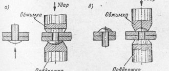
Crimpers (Fig. 9) are used for rolling and finishing the side and other surfaces of forgings. They consist of two parts: the lower part (bottom), inserted with a shank into the anvil, and the upper part (top), mounted on the handle. The swaging is produced by forging from steel U7, steels 40, 45, 50, 40X, processed by cutting and subjected to hardening and tempering to a hardness of 48...52 HRC on the working part and 30...40 HRC on the impacted part. The weight of the crimps ranges from 3 to 25...35 kg.
Rice. 7. Punchers
Rice. 8. Sweeping
Rice. 9. Upper (a) and lower (b) crimps
Rice. 10. Semicircular tampers: a – bottom; b – upper
Rice. 11. Nailers: a – simple; b – special
Tampers (Fig. 10) are used for broaching, making grooves, concave surfaces, as well as for finishing some sections or the entire surface of the forging. The shape of the working areas of the tamps is determined by their purpose and can be very diverse: flat, crescent-shaped, etc. Tampers are made by forging from steel U7, steels 50G, 40X with a hardness of the working parts of 40...45 HRC.
Nailers (Fig. 11) are metal plates made by forging from steel 45 or U7. They have holes for landing the heads of bolts, rivets, nails, etc.
Rice. 12. Forge mold
Forging mold (Fig. 12) is a cast plate made of steel 35L or 40L weighing up to 50 kg with through holes and shaped cutouts on the side surfaces. Designed for finishing forgings, punching holes and profile bending work.
Forging machine capabilities
The dimensional hammer is designed to perform the following blacksmith operations:
- bending parts (sometimes the workpiece is preheated);
- drawing (extension of the template by reducing the cross section);
- making holes (a punch/piercing is placed on the rod);
- sediment (reverse action to drawing);
- chopping (using axes).
Some of them are clear.
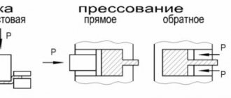
Rice. 2. Operations performed using a forging hammer.
Most well-known products perform all of the above operations. However, there is an important criterion for their classification.
Types of devices
This criterion is the type of substance used in the compressor cylinder. Hammers are distinguished:
Rice. 3. Mechanical forging hammer with foot drive.
- steam-air (steam or atmospheric air);
- hydraulic and hydrostatic (fluid under pressure);
- gasoline (work on the principle of internal combustion engines);
- gas (liquefied gas);
- electromagnetic (the energy of electric and magnetic fields is used);
- mechanical (powered by human physical effort);
- spring-spring (the spring accelerates the fall of the piston down);
- pneumatic (gas under pressure).
Among the listed devices, the forging pneumatic hammer stands apart. It has its own pneumatic cylinder, which eliminates the need to use additional energy sources and make the structure heavier. More details about the devices below.
Features of pneumatic hammers
The equipment refers to forging devices that perform all the previously listed operations, as well as twisting, cutting and shaping of workpieces.
They are controlled by hand lever or pedal. Structurally, the forging pneumatic hammer is complemented by an oil pump that lubricates the working cylinders (of which, by the way, there can be two). Conventionally, pneumatic hammers are divided into 2 groups:
- for artistic forging (models with a mass of falling parts up to 75 kg);
- for production (MPF - from 150 to 2000 kg).
The advantages of the equipment are energy intensity, sensitivity of adjustment of operating modes, ease of control, and durability. The disadvantage is the large size and weight, but the need for transportation rarely arises.
Hand holding tool for hand and hammer forging
The main supporting tool for hand forging and forging with hammers are pliers with various jaw geometries (Fig. 23). They are used to grip, hold, rotate and move workpieces and forgings during the forging process. Practice has developed rational types of pliers in relation to the overall dimensions and profiles of the workpieces being processed and the nature of the operations performed.
Rice. 23. Forging pliers: with longitudinal jaws (a – rectangular; b – square; c – cylindrical; d – conical); with transverse jaws (e – square bent; f – flat-round; g – bent; h – flat; i – rectangular; j – sharp)
Traditionally, pliers consist of two halves, each of which has a handle on one side and a sponge on the other. Each half of the pliers is fixed on a common axis. For better fixation of workpieces, the profile of both jaws of the pliers must correspond to the shape of the grasped end of the workpiece and be in contact with it along the maximum length of the jaws. (If necessary, to ensure better contact of the pliers’ jaws with the workpiece, they are heated to increase plasticity, they cover the cold workpiece with them and the jaws are pressed against the workpiece with hammer blows.)
The pliers must have free rotation of the handles on a common axis without jamming, exact alignment of the jaws when the pliers are compressed, and the handles of the pliers must be located in the same plane. Cracks, folds and nicks are not allowed. To increase the reliability of fixing the workpiece in the pliers, their handles are covered with various rings or C- and S-shaped hooks during operation.
During operation, the pliers are periodically cooled in water. Various types of pliers are made in accordance with GOST 11385–75 or according to GOST 11395–75 by forging from St 3 and steels 15, 20, 25, i.e. steels that do not harden when heated during operation (with carbon content 0.25%).
For transportation and manipulation both during heating and during forging of large, heavy workpieces and forgings, various devices are used: manipulators, devices or lifting and transport equipment of the forge shop.