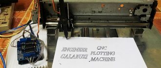
It is not difficult to make a CNC machine from a printer with your own hands. To do this, it is enough to have equipment that you don’t mind disassembling for spare parts. A CNC machine can be made with a stepper type electric motor. It can be used to mill or engrave various workpieces made of wood, plastic, and some metals. Homemade units from a CNC printer are capable of providing high speed processing of materials - up to 2 mm per second.
Let's start production
To start making a CNC machine from an old printer, you will need some parts that come with inkjet printers:
- Discs, pins, printer guides (it is recommended to use several old printers; the printers should not print);
- Disk from floppy drive.
- Material for creating the body - plywood, chipboard, etc.
- Drivers and controllers;
- Fastening materials.
The resulting numerically controlled machines will be able to perform many functions. Ultimately, it all depends on what device comes out of the car. The most common uses of inkjet printers are to make a CNC router, a torch (by installing a torch at the outlet of the device), and drills to make printed circuit boards.
The base is a wooden chipboard box. Sometimes they use ready-made ones, but doing it yourself is not difficult. It is worth considering that electronic components and controllers will be inside the box. It is better to assemble the entire structure with self-tapping screws. Do not forget that the parts must be located relative to each other at an angle of 90 degrees and fastened together as tightly as possible.
CNC milling machine at home (garage)
A kit with which you can assemble your own CNC milling machine. Ready-made machines are sold in China; a review of one of them has already been published on Muska. We will assemble the machine ourselves. Welcome... UPD
: links to files I will still provide a link to a review of the finished machine from AndyBig. I won’t repeat myself, I won’t quote his text, we’ll write everything from scratch. The title only indicates a set with engines and a driver, there will be more parts, I will try to provide links to everything. And this... I apologize in advance to the readers, I didn’t take any photos during the process on purpose, because... I didn’t intend to do a review at that moment, but I’ll take as many photos of the process as possible and try to give a detailed description of all the components.
The purpose of the review is not so much to brag as to show the opportunity to make an assistant for yourself. I hope with this review to give someone an idea, and perhaps not only repeat it, but also make it even better. Go…
How the idea was born:
It so happened that I have been involved with drawings for a long time. Those. my professional activity is closely connected with them. But it’s one thing when you make a drawing, and then completely different people bring the design object to life, and quite another thing when you bring the design object to life yourself. And if I seem to be doing okay with construction things, then not so much with modeling and other applied arts. So, for a long time I had a dream of making a zzzhik out of an image drawn in AutoCAD - and it’s in real life in front of you, you can use it. This idea popped up from time to time, but it couldn’t take shape into anything concrete until... Until I saw REP-RAP three or four years ago. Well, a 3D printer was a very interesting thing, and the idea of assembling it took me a long time to formulate; I collected information about different models, the pros and cons of different options. At one point, following one of the links, I ended up on a forum where people were sitting and discussing not 3D printers, but CNC milling machines. And from here, perhaps, passion begins its journey.
Instead of theory
In a nutshell about CNC milling machines (I write in my own words intentionally, without copying articles, textbooks and manuals). A milling machine works exactly the opposite of a 3D printer. In the printer, step by step, layer by layer, the model is built up by fusing polymers; in a milling machine, with the help of a cutter, “everything unnecessary” is removed from the workpiece and the required model is obtained.
To operate such a machine, the required minimum is required. 1. Base (body) with linear guides and a transmission mechanism (can be a screw or a belt) 2. Spindle (I see someone smiled, but that’s what it’s called) - the actual motor with a collet into which the working tool is installed - a milling cutter. 3. Stepper motors - motors that allow controlled angular movements. 4. Controller - a control board that transmits voltages to the motors in accordance with the signals received from the control program. 5. Computer with installed control program. 6. Basic drawing skills, patience, desire and good mood. ))
Point by point: 1. Base. by configuration:
I will divide it into 2 types, there are more exotic options, but there are 2 main ones:
With a moving portal: Actually, the design I chose, it has a base on which the X-axis guides are fixed. The portal on which the Y-axis guides are located moves along the X-axis guides, and the Z-axis unit moves along it.
With a static portal This design represents itself as a body; it is also a portal on which the Y-axis guides are located, and the Z-axis unit moving along it, and the X-axis is already moving relative to the portal.
by material: the body can be made of different materials, the most common: - duralumin - has a good ratio of weight and rigidity, but the price (especially for a hobby homemade product) is still depressing, although if the machine is intended to seriously earn money, then without options. - plywood - good rigidity with sufficient thickness, light weight, the ability to process anything :), and the actual price, sheet of plywood 17 is now quite inexpensive. - steel - often used on machines with a large processing area. Such a machine, of course, must be static (not mobile) and heavy. — MFD, plexiglass and monolithic polycarbonate, even chipboard — I also saw such options.
As you can see, the design of the machine itself is very similar to both a 3D printer and laser engravers. I deliberately do not write about the designs of 4, 5 and 6-axis milling machines, because... A homemade hobby machine is on the agenda.
2. Spindle. Actually, spindles come with air and water cooling. Air-cooled ones end up being cheaper because... for them there is no need to fence an additional water circuit; they operate a little louder than water ones. Cooling is provided by a rear-mounted impeller, which at high speeds creates a noticeable air flow that cools the engine housing. The more powerful the engine, the more serious the cooling and the greater the air flow, which may well blow dust (shavings, sawdust) of the workpiece in all directions.
Water cooled. Such a spindle works almost silently, but in the end, you still cannot hear the difference between them during the work process, since the sound of the material being processed by the cutter will be covered up. In this case, of course, there is no draft from the impeller, but there is an additional hydraulic circuit. Such a circuit must contain pipelines, a pump pumping liquid, as well as a cooling place (radiator with airflow). This circuit is usually filled not with water, but with either antifreeze or ethylene glycol.
There are also spindles of different powers, and if low-power spindles can be connected directly to the control board, then motors with a power of 1 kW or more must be connected through the control unit, but this is no longer about us. ))
Yes, straight grinders or milling cutters with a removable base are often installed in homemade machines. Such a decision may be justified, especially when performing work of short duration.
In my case, an air-cooled spindle with a power of 300W was selected.
3. Stepper motors. The most widely used motors are of 3 standard sizes NEMA17, NEMA23, NEMA 32; they differ in size, power and operating torque NEMA17 are usually used in 3D printers; they are too small for a milling machine, because you have to carry a heavy portal, to which additional lateral load is applied during processing. NEMA32 is unnecessary for such a craft, and besides, you would have to take another control board. my choice fell on NEMA23 with the maximum power for this board - 3A.
People also use steppers from printers, but... I didn’t have them either and still had to buy them and chose everything in the kit.
4. Controller A control board that receives signals from the computer and transmits voltage to stepper motors that move the axes of the machine.
5. Computer You need a separate computer (possibly a very old one) and there are probably two reasons for this: 1. It is unlikely that you will decide to place the milling machine next to the place where you are used to reading the Internet, playing with toys, doing accounting, etc. Simply because a milling machine is loud and dusty. Usually the machine is either in a workshop or in a garage (preferably heated). My machine is in the garage; in winter it mostly sits idle, because... no heating. 2. For economic reasons, computers are usually used that are no longer relevant for home life - very used. Requirements for a machine are basically nothing: - from Pentium 4 - the presence of a discrete video card - RAM from 512MB - the presence of an LPT connector (no USB I’ll say that since it has a driver that works via LPT, I haven’t looked into the new product yet) such a computer is either taken out of the closet, or, as in my case, bought for next to nothing. Due to the low power of the machine, we try not to install additional software, i.e. only the axis and control program.
then there are two options: - install windows XP (the computer is weak, remember, right?) and the MATCH3 control program (there are others, but this is the most popular) - install nixes and Linux CNC (they say that everything is also very good, but I haven’t mastered nixes )
I’ll add, perhaps, so as not to offend overly wealthy people, that it’s quite possible to install not just a fourth stump, but some kind of i7 - please, if you like it and can afford it.
6. Basic drawing skills, patience, desire and good mood. Here in a nutshell. To operate the machine, you need a control program (essentially a text file containing movement coordinates, movement speed and acceleration), which in turn is prepared in a CAM application - usually ArtCam, in this application the model itself is prepared, its dimensions are set, and the cutting tool is selected. I usually take a slightly longer route, make a drawing, and then save AutoCad *.dxf into ArtCam and prepare the UE there.
Next, we begin to smoke forums and collect information, I will give a couple of useful links: www.cncmasterkit.ru/viewtopic.php?f=18&t=2730 forumcnc.ru/forumdisplay.php?2-%CE%E1%F9%E8%E5-% E2%EE%EF%F0%EE%F1%FB www.cnczone.ru/forums/index.php?s=9d56244c6c291357dcdde8a4f369a711&showforum=2
Well, let’s begin the process of creating your own.
Before designing a machine, we take several points as starting points: — The axle shafts will be made of construction pins with M10 threads. Of course, there are undoubtedly more technologically advanced options: a shaft with a trapezoidal thread, a ball screw, but you need to understand that the price of the issue leaves much to be desired, and for a hobby machine the price is absolutely astronomical. However, over time I plan to upgrade and replace the pin with a trapeze. — Machine body material – 16mm plywood. Why plywood? Available, cheap, cheerful. There are actually a lot of options, some make them from duralumin, others from plexiglass. It's easier for me to use plywood.
Making a 3D model:
Scan:
Then I did this, there was no picture left, but I think it will be clear. I printed the scan on transparent sheets, cut them out and glued them onto a sheet of plywood. I cut out the parts and drilled the holes. Tools include a jigsaw and a screwdriver. There is one more little trick that will make life easier in the future: before drilling holes, squeeze all paired parts with a clamp and drill through, this way you will get holes equally located on each part. Even if there is a slight deviation during drilling, the internal parts of the connected parts will coincide, and the hole can be drilled out a little.
At the same time, we make specifications and start ordering everything. what I got: 1. The set indicated in this review includes: stepper motor control board (driver), NEMA23 stepper motors - 3 pcs., 12V power supply, LPT cord and cooler. aliexpress.com/item/3Axis-kit-3PCS-NEMA23-CNC-stepper-motor-81mm-308-oz-in-3A-3-axis-High-speed/719006867.html 2. Spindle (this is the simplest, but nevertheless, it does its job), fasteners and a 12V power supply. aliexpress.com/item/DC-12-48-CNC-300W-Spindle-Motor-Mount-Bracket-24V-36V-For-Engraving-Carving/679287021.html 3. Used Pentium 4 computer, most importantly on the motherboard There is an LPT and a discrete video card + CRT monitor. I bought it on Avito for 1000 rubles. 4. Steel shaft: f20mm – L=500mm – 2 pcs., f16mm – L=500mm – 2 pcs., f12mm – L=300mm – 2 pcs. I bought it here, at that time it was more expensive to buy in St. Petersburg. It arrived within 2 weeks. duxe.ru/index.php?cPath=37_67_68 5. Linear bearings: f20 – 4 pcs., f16 – 4 pcs., f12 – 4 pcs. 20 aliexpress.com/item/4pcs-SC20UU-Linear-Ball-Bearing-XYZ-Table-CNC-Router/1214529466.html 16 aliexpress.com/item/AE-4pcs-SC16UU-Linear-Ball-Bearing-XYZ-Table -CNC-Router/1214431787.html 12 aliexpress.com/item/4pcs-SC12UU-Linear-Ball-Bearing-XYZ-Table-CNC-Router/1297700376.html 6. Mounts for shafts: f20 – 4 pcs., f16 – 4 pcs. ., f12 - 2 pcs. 20 aliexpress.com/item/4pcs-SHF20-20mm-Linear-Rail-Shaft-Support-XYZ-Table-CNC/1221841376.html 16 aliexpress.com/item/4pcs-SHF16-16mm-Linear-Rail-Shaft-Support -XYZ-Table-CNC/1221839349.html 12 aliexpress.com/item/4pcs-SHF12-12mm-Linear-Rail-Shaft-Support-XYZ-Table-CNC/1221612308.html 7. Caprolon nuts with M10 thread – 3 pcs. I took it along with the shafts at duxe.ru 8. Rotation bearings, sealed - 6 pcs. There, but the Chinese also have a lot of them 9. PVS wire 4x2.5 is offline 10. Cogs, dowels, nuts, clamps - a bunch. This is also offline, in hardware. 11. A set of cutters was also purchased aliexpress.com/item/10pcs-3-175-1-5-8mm-PCB-Carbide-Cutting-Tools-PCB-End-Milling-Tools-In-Mini/922596359.html
So, we order, wait, cut and assemble.
Initially, the driver and power supply for it were installed in the case with the computer together.
Later, it was decided to place the driver in a separate case; it just appeared.
Well, the old monitor somehow changed to a more modern one.
As I said at the beginning, I never thought that I would write a review, so I am attaching photos of the components and will try to give an explanation of the assembly process.
First, we assemble three axles without screws in order to align the shafts as accurately as possible. We take the front and rear walls of the housing and attach the flanges for the shafts. We string 2 linear bearings on the X-axis and insert them into the flanges.
We attach the bottom of the portal to the linear bearings and try to roll the base of the portal back and forth. We make sure of the curvature of our hands, take everything apart and drill out the holes a little. This way we get some freedom of movement of the shafts. Now we attach the flanges, insert the shafts into them and move the base of the portal back and forth to achieve smooth sliding. Tighten the flanges. At this stage, it is necessary to check the horizontality of the shafts, as well as their coaxiality along the Z axis (in short, so that the distance from the assembly table to the shafts is the same) so as not to overwhelm the future working plane. We've sorted out the X axis. We attach the portal posts to the base; I used furniture barrels for this.
We attach the flanges for the Y axis to the posts, this time from the outside:
We insert shafts with linear bearings. We fasten the rear wall of the Z axis. We repeat the process of adjusting the parallelism of the shafts and secure the flanges. We repeat the same process with the Z axis. We get a rather funny design that can be moved with one hand along three coordinates. An important point: all axes must move easily, i.e. Having slightly tilted the structure, the portal itself should move freely, without any creaks or resistance.
Next we attach the lead screws. We cut the M10 construction stud to the required length, screw the caprolon nut approximately in the middle, and 2 M10 nuts on each side. It is convenient to do this by tightening the nuts a little, clamping the stud into the screwdriver and holding the nuts and tightening them. We insert the bearings into the sockets and push the pins into them from the inside. After this, we fix the studs to the bearing with nuts on each side and tighten them with a second one so that they do not come loose. We attach the caprolon nut to the base of the axle. We clamp the end of the pin into a screwdriver and try to move the axle from beginning to end and return it. A couple more joys await us here: 1. The distance from the nut axis to the base in the center (and most likely at the time of assembly the base will be in the middle) may not coincide with the distance in the extreme positions, because shafts may bend under the weight of the structure. I had to place cardboard along the X axis. 2. The shaft movement may be very tight. If you have eliminated all distortions, then tension may play a role; here you need to catch the moment of tightening the fixation with nuts to the installed bearing. Having dealt with the problems and having obtained free rotation from start to finish, we move on to installing the remaining screws.
We attach stepper motors to the screws: In general, when using special screws, be it a trapezoid or a ball screw, the ends are processed on them and then the connection to the motor is very conveniently made with a special coupling. But we have a construction pin and had to think about how to fasten it. At that moment I came across a piece of gas pipe and used it. It “screws” directly onto the stud and onto the engine, it goes into lapping, tightened it with clamps, and it holds quite well.
To secure the engines, I took an aluminum tube and cut it. Adjusted with washers. To connect the motors I took the following connectors:
Sorry, I don’t remember what they are called, I hope someone can tell me in the comments. GX16-4 connector (thanks Jager). I asked a colleague to buy electronics from a store; he just lives nearby, and it was very inconvenient for me to get there. I am very pleased with them: they hold securely, are designed for higher current, and can always be disconnected. We set up a working field, also known as a sacrificial table. We connect all the motors to the control board from the review, connect it to a 12V power supply, connect it to the computer with an LPT cable.
Install MACH3 on your PC, make the settings and try it out! I probably won’t write about the setup separately. This could take a couple more pages.
I'm so happy that I still have a video of the first launch of the machine:
Yes, when in this video there was a movement along the X axis there was a terrible rattling noise, unfortunately, I don’t remember exactly, but in the end I found either a loose washer or something else, in general it was solved without problems.
Next, you need to install the spindle, while ensuring that it is perpendicular (simultaneously in X and Y) to the working plane. The essence of the procedure is this: we attach a pencil to the spindle with electrical tape, thus creating an offset from the axis. As the pencil is lowered smoothly, it begins to draw a circle on the board. If the spindle is full, then the result is not a circle, but an arc. Accordingly, it is necessary to achieve the drawing of a circle by alignment. I have saved a photo from the process, the pencil is out of focus, and the angle is not the same, but I think the essence is clear:
We find a ready-made model (in my case, the coat of arms of the Russian Federation), prepare the UE, feed it to MACH and off we go! Machine operation:
Photos in progress:
Well, of course we go through initiation)) The situation is both funny and generally understandable. We dream of building a machine and immediately cutting out something super cool, but in the end we realize that this will take a lot of time.
In a nutshell: With 2D processing (simply sawing), a contour is specified, which is cut out in several passes. During 3D processing (here you can plunge into holivar, some argue that this is not 3D but 2.5D, since the workpiece is processed only from above), a complex surface is specified. And the higher the accuracy of the required result, the thinner the cutter is used, the more passes of this cutter are necessary. To speed up the process, roughing is used. Those. First, the main volume is sampled with a large cutter, then finishing processing is started with a thin cutter.
Next, we try, configure, experiment, etc. The 10,000-hour rule also applies here. Perhaps I won’t bore you any more with stories about construction, adjustment, etc. It’s time to show the results of using the machine—the product.
As you can see, these are basically sawn contours or 2D processing. Processing three-dimensional figures takes a lot of time, the machine is in the garage, and I go there for a short time. Here they will rightly remark to me - how about... building such a bandura if you can cut out the figure with a U-shaped jigsaw or an electric jigsaw? It is possible, but this is not our method. As you remember at the beginning of the text, I wrote that it was the idea of making a drawing on a computer and turning this drawing into a product that served as the impetus for the creation of this beast.
Writing a review finally pushed me to upgrade the machine. Those. The upgrade was planned earlier, but “never got around to it.” The last change before this was the organization of the machine house:
Thus, when the machine is operating in the garage, it has become much quieter and there is much less dust flying around.
The last upgrade was the installation of a new spindle, or rather, now I have two replaceable bases: 1. With a Chinese 300W spindle for small work:
2. With a domestic, but no less Chinese milling cutter “Enkor”...
With the new milling cutter new possibilities have appeared. Faster processing, more dust. Here is the result of using a semicircular groove cutter:
Well, especially for MYSKU Simple straight groove cutter:
Process video:
This is where I will wrap things up, but according to the rules, it would be necessary to sum up the results.
Cons: - Expensive. - For a long time. — From time to time we have to solve new problems (the lights were turned off, interference was turned off, something went wrong, etc.)
Pros: — The creation process itself. This alone justifies the creation of the machine. Finding solutions to emerging problems and implementing them is what, instead of sitting on your butt, you get up and go do something. — Joy at the moment of giving gifts made with your own hands. Here it should be added that the machine does not do all the work itself, in addition to milling, it still needs to be processed, sanded, painted, etc.
Thank you very much if you are still reading. I hope that my post, although it won’t encourage you to create such (or another) machine, will somehow broaden your horizons and give you food for thought. I also want to say thank you to those who persuaded me to write this opus; without it, I apparently didn’t even have an upgrade, so everything is a plus.
I apologize for any inaccuracies in wording and any lyrical digressions. A lot had to be cut, otherwise the text would have turned out simply immense. Clarifications and additions are naturally possible, write in the comments - I will try to answer everyone.
Good luck to you in your endeavors!
Update:
Promised links to files: yadi.sk/d/B5auVp9lt239P - drawing of the machine, yadi.sk/d/TNRUyj55t23JT - scan, format - dxf. This means that you can open the file with any vector editor. The 3D model is 85-90 percent detailed, many things were done either at the time of preparing the scan, or on site. I ask you to “understand and forgive.” )
Converting an inkjet printer to produce printed circuit boards
Lately I've been looking for ways to make PCB making easier. About a year ago I came across an interesting page describing the process of modifying an Epson inkjet printer to print on thick materials, including a copper circuit board. The article describes the upgrade of the Epson C84 printer, but I had an Epson C86 printer, but since then I think the mechanics of Epson printers are the same for all, so I decided to try to upgrade my printer.
In this article I will try to describe in as much detail as possible, step by step, the process of upgrading a printer for printing on printed circuit boards with copper bond.
Necessary materials: - well, of course, you will need the Epson C80 printer itself. - a sheet of aluminum or steel - staples, bolts, nuts, washers - a small piece of plywood - epoxy glue or superglue - ink (more on this later)
Tools: - grinder (Dremel, etc.) with cutting disc (you can try a monkey) - various screwdrivers, wrenches, hexagons - drill - hot air gun
Step 1. Disassemble the printer
The first thing I did was remove the rear paper output tray. Next, you need to remove the front tray, the side panels, and then the main body.
The photos below show the detailed process of disassembling the printer:
Step 2. Remove the internal parts of the printer
After removing the chassis from the printer, you will need to remove some of the internal components of the printer. First you need to remove the paper feed sensor. We'll need it in the future, so don't damage it when removing it.
Therefore, it is necessary to remove the central pinch rollers as they may interfere with power supply to the PCB. In principle, the side rollers can also be removed.
Finally, you need to remove the print head cleaning mechanism. The mechanism is held on by latches and can be removed very easily, but be very careful when removing it, because it includes different pipes.
The printer disassembly is complete. Now let’s start raising it.”
Step 3: Removing the print head platform
Let's begin the process of updating the printer. The work requires care and the use of protective equipment (eyes must be protected!).
First you need to unscrew the guide, which is fixed with two bolts (see Photo above). Unscrewed? We put it aside, we will still need it.
Now notice the 2 bolts next to the head cleaning mechanism. We also unscrew them. However, on the left side it is done a little differently, where you can cut the fasteners. To remove the entire head area, first carefully inspect everything and mark with a marker the places where you will need to cut the metal. And then carefully cut the metal with a hand grinder (Dremel, etc.)
Step 4: Clean the print head
This step is optional, but since you have completely disassembled the printer, it is best to clean the print head right away. Besides, there is nothing complicated about it. For this I used regular ear tips and glass cleaner.
Step 5: Install the print head platform. Part 1
Once everything is disassembled and cleaned, it's time to reassemble the printer, taking into account the space required to print the PCB. Or, as the keepers say, “the rise.” The amount of lift depends entirely on the material you will be printing on. In my modification of the printer, I planned to use a steel material feeder with an attached PCB. The thickness of the material feed platform (steel) was 1.5 mm, the thickness of the foil-covered circuit board, which I usually made boards from, was also 1.5 mm. However, I decided that the head should not put too much pressure on the material, so I chose a gap of about 9 mm. Also, I sometimes print on a double-sided PCB that is slightly thicker than one side.
To make it easier for me to check the lift level, I decided to use washers and nuts, the thickness of which I measured with a caliper. I also bought long bolts and nuts for them. I started with a front feeding system.
Step 6: Install the print head platform. Part 2
Breakdowns of dot matrix printers
Major breakdowns:
- The print head broke due to wear of the moving parts;
- The head cable was deformed due to its long service life;
- Sheets get stuck and deformed due to foreign objects or low-quality paper.
Some problems can be fixed at home with your own hands, others only in a workshop.
The printer does not turn on
Inspect the cable and replace if necessary. Check the network voltage with a multimeter, connect to another outlet.
If the printer still does not turn on, inspect the cord connector, which is located under the top cover. The fuses may have blown.
Printer won't turn on? Check the switch. If you have the skills, change it or remove it from the circuit and connect the cord directly.
The device turns on, but does not print
Start by checking your settings. Go to the “Printers and Faxes” menu and remove the printing ban. If there are tasks that have not yet been completed, delete them all.
Major breakdowns associated with mechanical damage:
- The contacts of the loops are broken;
- No power to the stepper motor, you may have to replace it completely;
- The head broke.
If you have already opened the printer, inspect all components and microcircuits. Check the drivers, they may have failed or a complete reinstallation of the printer on the PC is required.
The machine pulls a lot of paper
This type of printer malfunction in 99% of cases is due to a software glitch. Often the problem occurs when using roll paper, which is also typical for faxing.
IMPORTANT! Check the drivers on your PC, the program through which printing is carried out, and reinstall everything if necessary.
Wrong paper size is another common reason, so check this setting too and change it to the correct one.
A grinding noise is heard when the device is initializing
The main breakdowns associated with grinding occur for the following reasons:
- Stepper motor is broken;
- The gears are worn out;
- The guide bar is deformed.
You can get rid of problems only by replacing worn parts.
The machine does not pull paper
Printer faults for disposal are often related to the fact that the machine does not feed the paper.
There are two main problems:
- Engine failure.
- Failure of the broaching mechanism.
The machine crumples paper
During the broaching process, the sheets become wrinkled - this is due to a damaged broaching mechanism. Check the rubber rollers on the mechanism, they may be dirty.
The second common reason is poor paper quality and incorrectly selected density.
Software errors
Errors in the software are not a reason to write off the printer, as they can be easily fixed. They appear during a forced interruption of the printing process. To fix the problem, you just need to reinstall the drivers.
The problem occurs due to a power failure; a simple reboot will help.
The print head moves to the side
The fault is most often caused by the controller. The motor may break down or the contacts between the head and the controller may be broken.
Light print
The printer is rarely written off for this reason, but it is very sad when, after changing the cartridge, the characters become paler and paler. After installing a new cartridge, history repeats itself.
This is due to improper installation of the ink ribbon, which wears out prematurely. The scroll mechanism can also cause light print.
Prints strange characters
The problem occurs due to a faulty controller. How to fix it? Turn off the printer power immediately.
Fuzzy printing
Obvious character defects that are noticeable when comparing letters appear due to wear on the print head or needles.
Streaks appear when printing
Major breakdowns associated with wear of horizontal and/or vertical needles. Less often, the provoking factor is the electromagnet that controls them.
Minibar or bread box
Such things can also be assembled from an old printer, which many users like. The body of the product must be completely freed from all unnecessary parts in order to cover the resulting shape with fabric. The free space can be used to store valuables, alcoholic beverages or baked goods. The finished product will look appropriate not only in the kitchen, but also in the living room.
Future plans:
Still, make the table heated - bought a silicone heating pad for 220V 100W and a solid-state relay;
Design and print cable ducts and hide wires; On the Z axis, replace the M8 stud with a trapezoidal screw - purchased; Design radial airflow of the printed part. Screw on the Octoprint - it’s already there, installed on the OrangePi Zero, all that remains is to supply power. For this, allow me to take my leave, Thank you for your attention. With criticism, wishes and questions - please leave a comment.
PS Still, the Chukchi is a reader, not a writer.
Models of cars and motorcycles
The most original way to use broken office equipment was found by Spanish designer Enrique Conde. Use them to create models of motorcycles, helicopters and cars that will amaze with their entertainment and realism. This hobby is closer to art and requires certain skills.
Model car made from office equipment parts
So broken printers are useful for more than just sending them to landfill. With some changes and improvements, they can continue to benefit their owners.
Necessary materials
In order to make your own laser engraver using Arduino, you will need the following consumables, mechanisms and tools:
- hardware platform Arduino R3;
- Proto Board equipped with a display;
- stepper motors, which can be used as electric motors from a printer or DVD player;
- laser with a power of 3 W;
- laser cooling device;
- DC-DC voltage regulator;
- MOSFET transistor;
- electronic boards that control the laser engraver motors;
- limit switches;
- a housing in which you can place all the structural elements of a homemade engraver;
- timing belts and pulleys for their installation;
- ball bearings of various sizes;
- four wooden boards (two of them with dimensions 135x10x2 cm, and the other two - 125x10x2 cm);
- four round metal rods with a diameter of 10 mm;
- bolts, nuts and screws;
- lubricant;
- clamps;
- computer;
- drills of various diameters;
- a circular saw;
- sandpaper;
- vice;
- standard set of locksmith tools.
The electronic part of the machine will require the greatest investment
Product details
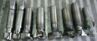
As a rule, only one element in a scanner or laser printer becomes unusable, and the remaining parts are quite suitable for work. The most valuable in this regard are MFPs and matrix devices. When disassembling the latter with your own hands, you can get many valuable parts.
Old printer
- Fasteners: screws, nuts, gears, bolts and other small items. For a home craftsman, any fasteners will be useful, since sometimes the lack of elements of the required diameter makes the work very difficult.
- The most valuable part in any type of printer is the hardened steel guide. In many Chinese and Korean cars, the guide is made of a cheap alloy and also bends under the weight of the drive belt. Canon or Epson inkjet machines are made of steel. This part is used when assembling CNC machines or homemade printing devices.
- The head sliding unit is plastic in inkjet machines and is only suitable for CNC engravers, while in matrix machines a bronze bushing is pressed into the block, so the part can be used on household metalworking machines.
- If you are planning to install a printing device, a Canon cartridge is the best option.
Canon cartridge
- The timing belt is a versatile part suitable for any application where power must be transferred from the stepper motor to ground. And the belt fixation unit can be found in MFPs, scanners and even in old Epson copiers.
- Stepper motor—provides paper movement. However, they are more powerful on older dot matrix and laser machines, and inkjet printer parts can be used effectively. Also, the motor, controller and driver can be removed from the old machine.
- Limit switches: provide paper quality control. A necessary part for a homemade device or press.
How does a stepper motor work?
Structurally, stepper motors can be divided into three large classes: motors with variable magnetic reluctance, motors with permanent magnets, and a hybrid class that combines the characteristics of the first two.
Stepper motors with variable reluctance have several poles on the stator and a rotor made of soft magnetic material that does not retain residual magnetization. For simplicity, the rotor in the figure has 4 teeth and the stator has 6 poles. The motor has 3 independent windings, each of which is wound on two opposite poles of the stator. The motor in the picture has a pitch of 30 degrees.
When the current is turned on in one of the coils, the rotor tends to take a position where the magnetic flux is closed, i.e. the rotor teeth will be opposite those poles on which the powered winding is located. If you then turn off this winding and turn on the next one, the rotor will change position, again closing the magnetic flux with its teeth. Thus, in order to carry out continuous rotation, you need to turn on the phases alternately. This type of motor is not sensitive to the direction of current in the windings, and due to the fact that the rotor is not magnetic, this type of motor can operate at high speeds. It is also easy to distinguish this type of motor from other steppers by simply rotating it by the shaft when it is turned off. The shaft will spin freely, while other types will clearly feel steps. Sometimes the surface of each stator pole is geared, which, together with the corresponding rotor teeth, reduces the pitch angle to several degrees. Motors with variable magnetic reluctance are now almost never used.
Permanent magnet motors consist of a stator with windings and a rotor containing permanent magnets. Due to the magnetization of the rotor, such motors provide greater magnetic flux and, as a result, greater torque than motors with variable reluctance.
The motor shown in the figure has 3 pairs of rotor poles and 2 pairs of stator poles. The stator has 2 independent windings, each of which is wound on two opposite poles. The engine in the figure has a step size of 30 degrees, the same as the previous one. When the current is turned on in one of the coils, the rotor tends to take a position where the opposite poles of the rotor and stator are opposite each other and to achieve continuous rotation it is necessary to switch on the phases alternately. In practice, permanent magnet motors typically have 48 to 24 steps per revolution, corresponding to pitch angles of 7.5 to 15 degrees).
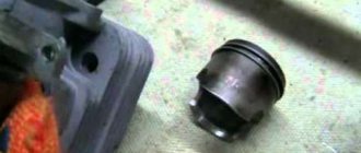
In practice, a permanent magnet motor looks, for example, like this. You can see such an engine in a laser printer. Permanent magnet motors are subject to back EMF from the rotor, which limits the maximum speed. This means that during a free run at high speeds, the engine will act as a generator and can burn the driver with current, which it generates itself. The same applies to hybrid engines.
Hybrid motors combine the best features of variable reluctance stepper motors and permanent magnet motors. Hybrid stepper motors provide smaller steps, higher torque, and higher speeds than variable reluctance motors and permanent magnet motors.
Typical steps per revolution for hybrid engines range from 100 to 400, corresponding to pitch angles of 3.6 to 0.9 degrees. The rotor of the motor shown in the figure has 100 poles (50 pairs), the motor has 2 phases, so the total number of poles is 200, and the pitch, accordingly, is 1.8 degrees.
A hybrid engine looks like this, for example.
Most modern stepper motors are hybrid, so let's take a closer look at the design of stepper motors of this type.
The motor rotor is divided transversely into two parts, between which there is a cylindrical permanent magnet. Due to this, the teeth of the upper half of the rotor are the north poles, and the teeth of the lower half are the south poles. In addition, the upper and lower halves of the rotor are rotated relative to each other by half the pitch angle of the teeth. The number of pairs of rotor poles is equal to the number of teeth on one of its halves. The toothed rotor pole pieces, like the stator, are assembled from separate plates to reduce eddy current losses. The stator of a hybrid motor also has teeth, providing a large number of equivalent poles as opposed to the main poles on which the windings are located. Typically 4 main poles are used for motors with 3.6 degree pitches and 8 main poles for 1.8 and 0.9 degree pitches. Rotor teeth provide less resistance to the magnetic circuit at certain rotor positions, which improves static and dynamic torque. This is ensured by the appropriate arrangement of the teeth, when part of the rotor teeth is strictly opposite the stator teeth, and part is between them.
Let's look at the longitudinal section of a hybrid stepper motor. The arrows indicate the direction of the magnetic flux of the permanent magnet of the rotor. Part of the flux (shown as a black line in the figure) passes through the rotor pole pieces, air gaps and the stator pole piece. This part is not involved in creating momentum.
As can be seen in the figure, the air gaps at the upper and lower pole pieces of the rotor are different. This is achieved by turning the pole pieces by half the tooth pitch, which was very clearly visible in the previous photo. Therefore, there is another magnetic circuit that contains minimal air gaps and, as a result, has minimal magnetic resistance. This circuit closes another part of the flow (shown in the figure by a dashed white line), which creates the moment. Part of the chain lies in a plane perpendicular to the figure, so it is not shown. The magnetic flux of the stator coil is created in the same plane. In a hybrid motor, this flux is partially closed by the rotor pole pieces and has little effect on the permanent magnet. Therefore, unlike DC motors, the magnet of a hybrid stepper motor cannot be demagnetized at any level of winding current.
The gap between the rotor and stator teeth is very small, about 0.1 mm. This requires high precision during assembly, so the stepper motor should not be disassembled to satisfy curiosity, otherwise its service may end.
To prevent the magnetic flux from closing through the shaft that passes inside the magnet, it is made of non-magnetic steel grades. To obtain large torques, it is necessary to increase both the field created by the stator and the field of the permanent magnet. This requires a larger rotor diameter, which worsens the torque to inertia ratio. Therefore, powerful stepper motors are sometimes constructed from several sections in the form of a stack. Torque and moment of inertia increase in proportion to the number of sections, and their ratio does not deteriorate.
We looked at the design of the hardware of stepper motors itself, but in addition to this, motors can also be divided according to the number and method of switching their windings.
There are only two main types - bipolar and unipolar.
A bipolar motor has one winding in each phase, which must be reversed by the driver to change the direction of the magnetic field. This type of motor requires a bridge or half bridge driver. In total, the bipolar motor has two windings and, accordingly, four outputs. An example of a common bipolar motor would be the 17HS4401 stepper motor
A unipolar motor also has one winding in each phase, but a tap is made from the middle of the winding. This allows you to change the direction of the magnetic field created by the winding by simply switching the winding halves. At the same time, the driver circuit is significantly simplified, which in the case of a unipolar motor should have only 4 simple keys. The middle terminals of the windings can be combined inside the motor, so such a motor can have 5 terminals, as in the figure, or 6 terminals if terminals AB and CD are separated. A unipolar motor with two windings and taps can be used in bipolar mode if the taps are left unconnected.
An example of a common five-lead unipolar motor would be the 28BYJ-48 brand stepper motor. This motor can be converted into a bipolar one by separating the AB and CD terminals, for which it is enough to cut one of the jumpers on the board under the blue cover.
Sometimes motors have 4 separate windings, for this reason they are mistakenly called 4-phase or four-winding motors. Each winding has separate terminals, so there are 8 terminals in total. With the appropriate connection of the windings, such a motor can be used both as unipolar and bipolar.
If we compare bipolar and unipolar motors, then bipolar motors have a higher power density, which means that with the same dimensions, bipolar motors provide greater torque. The torque produced by a stepper motor is proportional to the magnitude of the magnetic field created by the stator windings. There are two ways to increase the magnetic field - this is by increasing the current or the number of turns of the windings. A natural limitation when increasing the winding current is the danger of saturation of the iron core, but in practice a much more significant limitation is the limitation on motor heating due to losses due to the ohmic resistance of the windings. This is where the advantage of the bipolar motor design comes into play. In a unipolar motor, only half of the windings are used at any given time, and the other half simply takes up space in the core window, which forces the windings to be made with smaller diameter wire or the dimensions of the motor to be increased. At the same time, in a bipolar motor all windings are always working. In other words, on a bipolar motor of the same power it is necessary to wind half as much copper winding wire as on a unipolar one, and if the windings are equal in mass, then the bipolar motor will be about 40% more powerful.
In practice, you can find both types of motors, since bipolar ones are cheaper due to lower material consumption, while unipolar ones require much simpler drivers. Currently, hybrid bipolar engines are the most widely used.
Where to buy SD?
You can buy stepper motors in our 3DIY store with delivery throughout Russia!
Creating a homemade machine
Before converting printers or scanners into mini-machines capable of performing milling work, it is necessary to assemble the structure frame and its main components as accurately as possible.
The top cover of the device requires the installation of the main axes, the main components of all professional machines. There should be only three axes; work should begin by fixing the y-axis. To create a reference book, a furniture reference book is used.
Separately, we note the creation of a CNC from a scanner. Converting this device is the same as converting an old inkjet printer at hand. Any scanner has stepper motors and pins, thanks to which the scanning process is carried out. In a machine, these motors and pins will be useful, instead of scanning and printing, milling will be done, and instead of head movement, the printer will use the movement of the milling device.
For the vertical axis in a homemade CNC we will need parts of the unit (the guide along which the laser moved).
Printers have so-called strips, they act as lead screws.
The motor shaft must be connected to the stud using a flexible coupling. All boards must be attached to a chipboard base. In this type of design, the milling machine moves only in the vertical plane, and the part itself moves horizontally.
What will serve as the basis?
Making a homemade CNC machine from a printer is possible using matrix-type equipment. You can use any that is available, regardless of the manufacturer's brand. Also, for high-quality control and efficient operation of the units, it is necessary to remove other parts from the printer - the motor, carriages, toothed belts, guides, and various gears.
Useful parts
Electronic filling
There are two options:
- You arm yourself with a soldering iron, flux, solder, a magnifying glass and understand the chips from the printer. Locate the 12F675 and LV1745 printer control boards. Work with them by creating a CNC control board. You will need to connect them to the back of the CNC machine, under the power supply (we also get this from a sick printer).
- Use the factory CNC machine controller. Offhand: five-axis CNC controller. Homemade electronics are great, but the Chinese greatly undercut their prices. Then, with a light click of the mouse, we order CNC from them, because in Russia it is not possible to buy such a CNC device. The 5-axis CNC controller CNC Breakout Board allows you to connect 3 limit motor inputs, a stop button, automatic control of the Dremel and up to 5 drivers to control the stepper motor of a home-made machine.
This CNC is powered by a USB cable. In the home version of the CNC, the IC printer control board must be powered by the CNC machine's power supply.
A stepper motor will have to be selected for a homemade CNC machine with a power of up to 35 volts. With other options, the CNC controller runs the risk of failure.
Remove the power supply from the printer. Connect the power supply, on/off switch, CNC controller and Dremel.
Run the cable from the laptop/PC to the machine control board. Otherwise, how will you load tasks into the machine? Speaking of homework, download Math3 for drawing. CorelDraw is suitable for non-industrial design professionals.
On a homemade CNC machine you can cut plywood (up to 15 mm), textolite up to 3 mm, plastic, wood. The product will not be longer than 30-32 cm.
Quite often, among owners of poorly functioning or already faulty office equipment, the question arises of what can be done with an old printer. Of course, the easiest way to do this is to send you a used inkjet or laser printer. But if you have free time and a little desire, you can turn a printer into a CNC machine, that is, CNC equipment, which has found wide application for solving both amateur and professional problems. You can learn more about this below, but first let's look at what you can get out of your old printing device.
Advantages of Stepper Motor
- The angle of rotation of the rotor is determined by the number of pulses supplied. The stepper motor does not rotate smoothly, but in steps; the step has a certain value. Therefore, in order to rotate the shaft to the desired position, we simply apply a known number of pulses.
- position dependence on input pulses ensures positioning without feedback. One step - one impulse. No matter how many pulses were given, the engine moved to that position.
- The engine provides full torque when stopped. This is good because the powered motor does not need a brake to fix the position of the shaft; it can be braked using the driver.
- Precise positioning and repeatability. Good stepper motors have an accuracy of 3 to 5% of the step size. This error does not accumulate from step to step, since per one revolution of the engine there is a constant number of steps, after completing which we will always get a turn of 360 degrees.
- high reliability. High engine reliability is associated with the absence of brushes. The service life is actually determined by the service life of the bearings
- possibility of obtaining low rotation speeds. To obtain a low engine rotation speed, it is enough to slow down the pulse rate, then the engine will move more slowly and its rotation speed will be low.
- high torque at low speeds. High torque at low speeds eliminates the need for a gearbox, which simplifies the design of the equipment
- A fairly large range of speeds can be covered. The rotation speed of the motor is proportional to the frequency of the input pulses; by supplying them faster or slower, we also influence the rotation speed.
Cabinet or drawer for needlework
A broken printer can be a good cabinet or chest.
An even more interesting solution is to make an embroidery box. For this purpose, the internal space of the device is divided into cells with fabric-covered plywood. Fabric pockets are made for necessary small items. The mirror can be glued to the back of the lid with liquid nails, and the body can be painted with paints.
Embroidery box
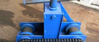
Universal machine
From an old printer you can make a very original device that can be used to solve many problems. To work, you need to prepare a set of construction tools for the stud. Experts recommend having a vice, side cutters, pliers, a hacksaw and screwdrivers on hand. Manufacturing principle of the machine:
- From a regular piece of plywood you need to cut four squares 37x37 (2 pieces), 9x34, 34x37.
- All workpieces must be fastened together with self-tapping screws. You need to pre-drill holes in the plywood with a drill.
- Duralumin corners can be safely used as guides along the Y axis. The product should be as durable as possible. To attach the corners to the side walls of the case, it is necessary to make a protrusion of two millimeters. Metal parts must be screwed through the central surface using self-tapping screws.
- The propeller can be built from a construction pin. Interaction with the engine will occur through the clutch.
- Instead of a spindle, you need to install a Dremel on the CNC wall, which will be equipped with a holder consisting of a bracket for the board.
- A sheet of plywood with a 19x9 cm base is ideal for making high-quality supports. You will also need to drill corresponding sockets for the guides.
- At the final stage, the master will have to assemble the axle using Dremel brackets. The finished machine is placed on the prepared surface.
The result is a printer like this:
Dimensions (H*W*D) - 38*32*27 cm (without coil mounting) Mechanics:
Kinematics - CoreXY Dimensions of the printing area (X*Y*Z) - 124*130*105 mm Dimensions of the guide axes X, Y - diameter 6 mm, length 200 mm GT2-20 spools are used, GT2 belt width 6 mm Z axis - diameter 8 mm, length 220 mm, moved by an M8 screw pin.
Extruder - Bowden MK8 Hotend - Chinese E3D V6, 1.75 filament. Electronics:
Power supply 12V 10 A (Chinese) Arduino Mega 2560, RAMPS 1.4, MKS Mini 12864LCD Drivers - 2*TMC2208 (X,Y axis), 2*A4988 (Z axis, extruder) Mechanical limit switches.
Software:
firmware - Marlin 1.1.5 slicer - Simplify3D 4.0.1
Additional photos
Compact shocker
Even beginners know that an old inkjet printer can be used to make an original part that will be useful in difficult situations. The product contains a universal part - a board equipped with high voltage converters. The master must be extremely careful, as the procedure is quite dangerous. The work requires knowledge in the field of electronics. Beginners should avoid this task. If everything is done correctly, you can end up with a stylish shock keychain.
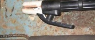
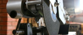
Burner with nichrome thread
The device is equipped with a different impact mechanism, which gives the burnt images significant volume, the drawings seem natural and rich. The image is applied to the wood using a nichrome thread; the brightness of the color depends on the heating temperature of the thread and the time of exposure to the surface.
When drawing shadows, the wire tip must be quickly passed over the surface, without stopping on the tree. But if the drawing requires bright and thick lines, the wire can be left for 3-4 seconds.
Experts include the following advantages of the machine:
- The saturation of the picture is adjusted on the device with a special button.
- The function helps to give the image any intensity depending on the client’s wishes.
- It's easy to burn pictures on wood and leather.
- To draw a picture measuring 25x25 centimeters, it will take an experienced specialist 3 hours.
- The drawing will not be pixelated when you stretch and enlarge the photo.
- During burning, the device does not emit harmful light.
Assembly
We weld batteries with flaws to each other. We solder the wire at the connection point. We do the same with the plus. Since batteries are used, when disassembling I recommend not tearing the nickel-plated tape, but cutting it. Then it's easier to solder the wires. I had a minus, I had to pay carefully. We put the wires in one direction, there will be a charge controller. Caps for the case, and card holders are also cut out of plastic. PVC plastic, I really enjoyed working with it. Soft, works with a construction knife. I mark the holes for all connectors and the switch. I cut with a knife. I make small indentations for the boards. I attach the cards with hot glue. They stick perfectly, there is no pressure on the outside. Solder the wires to the controller. From the controller to the other side of the lamp to the boost converter board. To secure the batteries in the case, I will use pieces of wine cork. It is necessary to cut a piece on the cork to allow the threads to pass freely. We insert the batteries, the plug and install the plug with the charge controller. Everything is holding up great. Solder the switch to the plug on the side of the boost converter. We break the positive or negative power cable. The one that comes from the battery charge controller. The wires are unsoldered. We carefully put everything in a case and don’t forget the wine cork. You can also glue it with superglue. This is the converter side. This is what it looks like from the charging connector. This causes the indication LEDs to light up during operation. You could drill a hole and fill it with hot glue, but I didn't think much about it and left it as is. Here is such a strong and quite affordable Powerbank. In general, I think that the photoconductor is a good element for this. I advise you to repeat this device.
Printing examples
Everything was printed with PLA plastic from Bestfilament, temperature 210-215 degrees, blowing after the first layer.
bathtub boat (visual benchy) - a complex model, like 3DBenchy, bridges, arches, many small details, reduced in size by 2 times, printed without supports, infill 30%, layer 0.1
More photos of the boat
Marvin is another test model, I have a whole squad of them Layer 0.2, fill 30%
In all the photos where there are holes, closed with yellow-brown plugs, they were printed on the same printer - the RepRap ideology in action. And under the spoiler there are a couple of models
Photo of the printed
Infinite cube masturbator Cool model, printed without supports in one piece, printed 3 pieces, someone always takes it away.
(KUT) Keychain Utility Tool - settled in my bag just in case.
How to connect a mini drill to a power source
The last step in assembling the device is connecting to a power source. Now the second part that you removed from the printer will come in handy: the power supply. Disconnect the wire from it that led to the printing mechanism.
Remove the board and solder the mini drill wire to the power supply. This is an important stage, since the success of all work will depend on the quality of the weld.
That's all, you can check how the mini drill will work and try it with different accessories.
This miniature tool can perform a variety of jobs. You can use it for sharpening, grinding, drilling and engraving
As you can see, everything is quite simple. Even if you have little experience working with an electrician, you can handle it. In exchange for a broken printer, you will receive an excellent working portable power tool, the factory equivalent of which costs at least 2 thousand rubles. Great idea, right?
Master Class
Below is a plan of action that you need to follow to make equipment such as a mini drill. First of all, you need to find a regular plastic bottle cap. You need to make a hole in it for the switch, as shown in the photo. Another hole needs to be opened for power supply. Then we thread the contact, one end needs to be soldered to the motor, and the other with a break (the switch will be located in it). The plug should be fixed with glue on the motor.
Such mini-equipment requires protection - this is human safety, which cannot be ignored. To do this, you need to cut a piece 6 cm long (including the neck) from a simple transparent plastic bottle, as shown in the photo. The edges need to be melted with a lighter for strength. You will need several neodymium magnets, which need to be placed on the glue inside the neck.
We put the protection on the case - it will be held in place by magnets. Now you need to heat shrink everything - this can be done using an open flame. We connect the switch. To do this, the ends of the wire need to be soldered to the switch. We connect to the energy source - the power supply by soldering. The mini drill is ready and can be used with a variety of attachments.
Compact wind generator
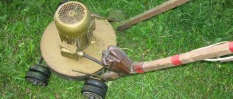
It is important to note that even such a multifunctional product can be made from an old printer. A ready-made wind generator will be able to convert ordinary wind into electricity, which is quite enough for ordinary household needs. The most effective are laser stepper motors or MFPs. Progress:
- To remove the motor, you must carefully disassemble the old printer.
- The master needs to assemble a rectifier: two electrodes are taken for every fourth stage.
- PVC pipes are ideal for blades, since in this case there will be no difficulties in choosing the optimal degree of curvature.
- The slate sleeve is mechanically adjusted to the shaft. All parts must be compact so that a lightweight structure can ultimately be assembled.
- A sleeve is put on the shaft, fixed, and then the blades are fixed. The product should be as balanced as possible.
- The motor is inserted into a piece of PVC pipe and secured with bolts. A duralumin weather vane is attached to the end. The structure is supported by a vertical pipe.
Sources
- https://VseOChpu.ru/chpu-iz-printera/
- https://les-tish.ru/shite/chto-mozhno-sdelat-iz-printera.html
- https://FB.ru/article/465772/chto-mojno-sdelat-iz-starogo-printera-opisanie-rasprostranennyie-variantyi
- https://SdelaySam-SvoimiRukami.ru/4545-ne-vybrasyvajte-staryj-kartridzh-sdelajte-iz-nego-poverbank.html
- https://homius.ru/dremel-iz-printera.html
[collapse]
How much did it cost:
The only question left is: how much did it cost?
Now let’s count Stepper motors 4 pcs. — it’s free for me, if you look at flea markets it’s $2-3, we’ll take $10 Guides D6mm, 200mm 4 pcs. — $1.72 TMC2208 drivers 2 pcs. — $12.32 turbine 5015 — $1.98 fan 3010 — $0.69 Desk sticker — $5.12 adapter for RAMPS — $0.92 MKS Mini 12864LCD — $12.70 (cost me $9) Mega 2560 R3 for arduino + 1pcs RAMPS 1.4 Controller + 4pcs A4988 Stepper Driver Module — $17.04 3D V6 Long distance J-head Hotend for 1.75mm 3D Bowden Extruder 0.4 Nozzle — $3.64 MK8 extruder — $3.42 LM6LUU 6mmx12mmx35mm 2 pcs. — $1.34 LM6UU 6mmx12mmx19mm 4 pcs. — $1.2 Guides D6mm, 200mm 4 pcs. — $1.72 LM8UU 4 pcs. — $1.08 guides D8mm, 240 mm 2 pcs. — $0.94 Bearing 608ZZ 9 pcs. — $1.8 (I don’t give links, I bought it on sale for $0.2, quality g, normal ones from the Minsk plant for $1) Clutch 5mm*8mm*25mm — $0.93 GT2 belt 6mm, 2m — 2.87 $ GT2-20 spools 2 pcs. — $2.15 limit switches 3 pcs. — 1.62 $ Total for spare parts ~ 85 $ Case — 5 $ PLA plastic — maximum 10 $ Since linkcnc Store, BIG TREE TECH and others have paid delivery, and maybe I forgot to indicate some small things, we will add 15 $. Total
$115 I also ask you to take into account that the above prices are approximate, you can find them cheaper, the guides can be removed from old equipment, and you can buy electronics in stores that specialize in this.