Test 1 Option 14
What is a mosaic (or block) metal structure? A polycrystal consists of a large number of grains, while in neighboring grains the crystal lattices are oriented differently. Figure 1 – Misorientation of grains and blocks in metal a – grains; b – blocks; Θ – angle between grains. Grain sizes are up to 1000 microns. The misorientation angles are up to several tens of degrees. The boundary between grains is a thin surface zone of 5-10 atomic diameters with a maximum violation of the order in the arrangement of atoms. The structure of the transition layer promotes the accumulation of dislocations in it. At the grain boundaries there is an increased concentration of impurities, which reduce the surface energy. However, even inside the grain, the ideal structure of the crystal lattice is never observed. There are areas misoriented one relative to the other by several degrees. These areas are called fragments. The process of dividing grains into fragments is called fragmentation or polygonization. In turn, each fragment consists of blocks less than 10 microns in size, misoriented at an angle of less than one degree. This structure is called block or mosaic. The study of substructure is of great importance, since the size and misorientation of subgrains affect many properties of metals.
What is tensile strength (σB)? How is this characteristic of mechanical properties determined?
Strength is the property of materials, under certain conditions and limits, to withstand certain impacts without collapsing. Figure 2 - Tensile diagram of a low-carbon steel sample. The mechanical properties of steel (including strength) are usually determined using a conventional tensile diagram. GOST 1497-84 regulates strength properties, including temporary tensile strength. For tensile testing, standard samples are used. Testing machines are equipped with a device that records the tensile diagram. Increasing the load above PC causes more significant plastic deformation throughout the entire volume of the metal. Temporary tensile strength (or tensile strength) σB – conditional stress corresponding to the highest load PD preceding the failure of the sample: σB = PD/F0 kgf/mm2. In ductile metals, starting from stress σB, the deformation is concentrated in one area of the sample, where a local narrowing of the cross section appears, the so-called neck. As a result of the development of multiple slip, a high dislocation density is formed in the neck, and nucleation discontinuities arise, the enlargement of which leads to the formation of pores. Merging, the pores form a crack, which propagates in the direction transverse to the tensile axis, and at some point the sample fails (point K in Figure 2).
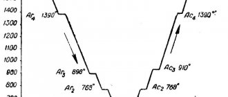
Draw an iron-iron carbide phase diagram, indicate the structural components in all areas of the diagram, describe the transformations and construct a cooling curve (using the phase rule) for an alloy containing 5.5% C. What is the structure of this alloy at room temperature and what is such an alloy called ? Primary crystallization of alloys of the iron-carbon system begins upon reaching temperatures corresponding to the ABCD line (liquidus line) and ends at temperatures forming the AHJECF line (solidus line). When alloys crystallize along the AB line, crystals of a solid solution of carbon in α-iron (δ-solution) are released from a liquid solution. The crystallization process of alloys with a carbon content of up to 0.1% ends along the AN line with the formation of an α (δ) solid solution. A peritectic transformation occurs on the HJB line, as a result of which a solid solution of carbon in γ-iron, i.e., austenite, is formed. The process of primary crystallization of steels ends along the AHJE line. At temperatures corresponding to the BC line, austenite crystallizes from the liquid solution. In alloys containing from 4.3% to 6.67% carbon, at temperatures corresponding to the CD line, crystals of primary cementite begin to precipitate. Cementite that crystallizes from the liquid phase is called primary. At point C at a temperature of 1147°C and a carbon concentration in a liquid solution of 4.3%, a eutectic is formed, which is called ledeburite. The eutectic transformation with the formation of ledeburite can be written by the formula ЖР4.3Л[А2.14+Ц6.67]. The process of primary crystallization of cast iron ends along the ECF line with the formation of ledeburite. Thus, the structure of cast irons below 1147°C will be: hypoeutectic - austenite + ledeburite, eutectic - ledeburite and hypereutectic - cementite (primary) + ledeburite. Transformations occurring in the solid state are called secondary crystallization. They are associated with the transition of γ-iron to α-iron upon cooling and the decomposition of austenite. The GS line corresponds to the temperatures at which the transformation of austenite into ferrite begins. Below the GS line, the alloys consist of ferrite and austenite. The ES line shows the temperature at which cementite begins to separate from austenite due to a decrease in the solubility of carbon in austenite with decreasing temperature. Cementite released from austenite is called secondary cementite. At point S at a temperature of 727°C and a carbon concentration in austenite of 0.8%, a eutectoid mixture consisting of ferrite and cementite, called pearlite, is formed. Pearlite is obtained as a result of the simultaneous precipitation of ferrite and cementite particles from austenite. The process of transformation of austenite into pearlite can be written by the formula A0.8P[F0.03+Ts6.67]. The PQ line indicates a decrease in the solubility of carbon in ferrite upon cooling and the release of cementite, which is called tertiary cementite. Consequently, alloys containing less than 0.008% carbon (point Q) are single-phase and have the structure of pure ferrite, and alloys containing carbon from 0.008 to 0.03% have a ferrite + tertiary cementite structure and are called technical iron. Hypoeutectoid steels at temperatures below 727ºC have a ferrite + pearlite structure, and hypereutectoid steels have pearlite + secondary cementite in the form of a network along the grain boundaries. In hypoeutectic cast irons in the temperature range 1147–727ºС, upon cooling, secondary cementite is released from austenite due to a decrease in carbon solubility (ES line). Upon reaching a temperature of 727ºС (PSK line), austenite is depleted in carbon to 0.8% (point S), turning into pearlite. Thus, after final cooling, the structure of hypoeutectic cast irons consists of pearlite, secondary cementite and converted ledeburite (perlite + cementite). The structure of eutectic cast irons at temperatures below 727ºС consists of transformed ledeburite. Hypereutectic cast iron at temperatures below 727ºС consists of converted ledeburite and primary cementite. The phase rule establishes the relationship between the number of degrees of freedom, the number of components and the number of phases and is expressed by the equation: C = K + 1 – Ф, where C is the number of degrees of freedom of the system; K – number of components forming the system; 1 – number of external factors (we consider only temperature as an external factor, since pressure, except for very high pressure, has little effect on the phase equilibrium of alloys in solid and liquid states); Ф – number of phases in equilibrium. An alloy of iron and carbon containing 5.5% C is called hypereutectic cast iron. Its structure at room temperature is cementite (secondary) + pearlite + ledeburite (perlite + cementite).
a) b) Figure 3: a - iron-cementite diagram, b - cooling curve for an alloy containing 5.5% carbon
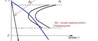
A cutting tool made of U10 steel was overheated during hardening. Why is overheating harmful and how can this defect be corrected? Correct the structure and assign a heat treatment mode that ensures normal operation of the tool. Describe its structure and properties. When temperatures are too high and held for too long, a coarse grain structure called a superheat structure occurs. Overheating is characterized by a coarse-crystalline shiny fracture. Overheating of hypereutectoid steel can be eliminated by normalization. Normalization consists of hypereutectoid steel to a temperature above the Acm point, also by 40-50°C, a short holding period to warm up the charge and complete phase transformations, and cooling in air. The normalization temperature of U10 steel is 830-850°C. Accelerated cooling in air leads to the decomposition of austenite at lower temperatures, which increases the dispersion of the ferrite-cementite structure and increases the amount of pearlite or, more precisely, sorbitol or troostite. To obtain the necessary performance properties, steel must be hardened and low tempered. At room temperature, U10 steel has the structure of cementite and pearlite. Up to temperature Ac1, the original structure is preserved. At temperature Ac1, pearlite transforms into austenite with a carbon content of 0.8%. When heated above the Ac1 point, cementite dissolves in austenite (in accordance with the SE line). An increase in temperature above the Acm point causes austenite grain growth. Critical points for U10 steel: Ac1 = 730°C; Аcm = 800°С. For hardening, hypereutectoid steels are heated 50-70°C above the Ac1 point. Thus, the heating temperature for hardening is 780-800°C. At these temperatures, steel contains cementite along with austenite. Therefore, after quenching, the structure of hypereutectoid steels will contain martensite with cementite and a small amount of retained austenite. The cooling medium during quenching is industrial oil. Surface hardness after hardening is 62-64 HRC. To relieve stress and stabilize the structure after hardening, the products are subjected to low tempering.
Using the iron-cementite phase diagram, determine the full and partial annealing and normalization temperatures for steel 40. Characterize these heat treatment regimes and describe the structure and properties of the steel. Complete annealing consists of heating hypoeutectoid steel 30-50°C above the temperature corresponding to point Ac3 (for steel 40 Ac3 = 790°C), holding at this temperature for complete heating and completion of phase transformations in the bulk of the metal, and subsequent slow cooling. With slow cooling, steels approach phase and structural equilibrium. The structure after annealing is ferrite + pearlite. After annealing, steel has low hardness and strength. The main purposes of annealing are: recrystallization of steel (grain refinement), relieving internal stresses, reducing hardness and improving machinability. Partial annealing differs from complete annealing in that the steel is heated to a lower temperature (slightly above point A1 (for steel 40 A1 = 730°C)). Partial annealing of hypoeutectoid steels is used to improve machinability. With incomplete annealing, partial recrystallization of the steel occurs due to the transition of pearlite to austenite. Excess ferrite is only partially converted to austenite. The structure after annealing is ferrite + pearlite. Normalization consists of heating hypoeutectoid steel to a temperature exceeding the Ac3 point by 40-50 °C, holding it for a short time to warm up the charge and complete phase transformations, and cooling in air. Normalization causes complete phase recrystallization of the steel and eliminates the coarse grain structure obtained during casting, rolling, forging or stamping. Normalization is widely used to improve the properties of steel castings instead of quenching and tempering. Accelerated cooling in air leads to the decomposition of austenite at lower temperatures, which increases the dispersion of the ferrite-cementite structure and increases the amount of pearlite or, more precisely, sorbitol or troostite. This increases the strength and hardness of normalized medium and high carbon steel compared to annealed steel.
Annealing on granular pearlite
To obtain the structure of granular pearlite, pendulum annealing is carried out, after which eutectoid and hypereutectoid steels provide good machinability, the speed of the cutting process increases and the surface quality improves. This type of T/O is suitable for thin sheets before cold stamping and rods before cold drawing. The result is improved plastic properties.
The pendulum annealing mode consists of several heating cycles above the critical point A3 with slow cooling to +670...+700°C. Three such cycles make it possible to obtain a structure with 100% granular perlite. Final cooling is in air.
Possible defects after hardening
Heating, holding, cooling and tempering of steel are carried out in accordance with technological maps developed by specialists. Violation of the developed and approved technical process and/or heterogeneity of the workpiece structure can cause various defects. Among them:
- Uneven heating and/or cooling. They lead to deformations and the formation of cracks, non-uniform composition and non-uniform mechanical characteristics.
- Burnout. Occurs due to the penetration of oxygen molecules into the metal surface. As a result, oxides are formed that change the performance characteristics of the surface layer. This defect occurs due to the burning of carbon from the steel caused by excess oxygen in the furnace.
- Water entering the oil cooling bath. This violation of the technical process leads to the appearance of cracks in the product.
All of the above defects are irreparable.
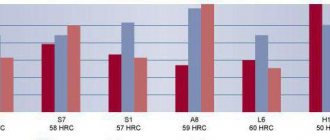
Vickers method
When measuring hardness using the Vickers method, a pyramid-shaped tip is used as an indenter, the edges of which converge at an angle of 136 degrees. To ensure the accuracy of the test, it is important to observe several points:
- the load must be placed strictly in the center of the diamond tip;
- the load application vector must be strictly perpendicular to the surface of the test sample.
Measurements take place according to the following algorithm: the sample being tested is placed on a special table, and the indenter is pressed into the sample from above immediately with the required load level (the maximum possible value is up to 100 kgf). Next, the indenter is held under load for 10-15 seconds. After removing the indenter, the indentation depth and indentation diagonal are measured.
Next, a calculation takes place according to the form, which takes into account the ratio of the applied load to the diagonal of the indentation and the time during which the test took place. Hardness is indicated in kgf/mm2 format, display format HV. The Vickers method, due to the use of a diamond tip, allows for more accurate measurements than the Brinell method.