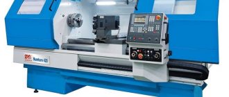
Metal planing machines are designed for roughing and finishing processing of workpieces of various shapes. Thanks to the ability to replace cutters, you can achieve the desired processing speed, cut various metals, and obtain the required level of productivity. Used in industry, workshops, repair shops.
Cross-planing machine (Photo: Instagram / kubanzheldormash)
Specifications
Technical characteristics of planing machines:
- working surface size - from 200x180 mm to 1500x6000 mm;
- maximum height of the processed workpiece - up to 1.23 m;
- the maximum distance between the working surface and the crossbar is 1.25 m;
- permissible weight of parts - up to 8 tons;
- electric motor power, depending on the machine model - from 500 W to 150 kW;
- the maximum angle of rotation of the incisors in both directions is 600;
- processing speed - from 3 to 60 m/min.
Classification of cutters for planing unit
Cutters that are used to process parts on metal planing machines are divided into categories according to the following criteria:
- cutting part material;
- shape and size of the rod;
- type of cutting tool.
The cutting part of the tool can be made entirely of high-speed steel or with a carbide nozzle. In the first case, the incisors are called solid, and in the second - compound.
Metal-ceramic alloys or mineral-ceramic materials are used as attachments for the cutting part. The holder of such a tool is made of structural steel.
Video:
High-speed bits are attached to the holder by welding, soldering or mechanically.
Depending on the shape of the head, the incisors can be retracted or curved. Depending on the direction of feed of the workpiece being processed, cutting tools are divided into right and left.
IMPORTANT TO KNOW: Review of equipment for cold metal forging
The type of tool is determined by the type of specific operation.
The most common types are:
- checkpoint;
- finishing;
- trimming;
- cutting;
- shaped.
Planing of metal is performed only with the working movement of a cutter or table with a fixed workpiece.
When the cutting tool is secured in a folding holder, its wear occurs more slowly.
Because during the reverse stroke it tilts back and slides freely over the surface.
Design and principle of operation
The mechanical part of planing machines consists of the following elements:
- cast iron or steel frame - the main part of the structure that bears the main loads, used to accommodate the assembly with the cutting tool and the work table;
- working surface - designed for placing workpieces and fastening them;
- guides—necessary for moving the slider or working surface;
- slider - performs translational movements when processing workpieces;
- a cutter used for cutting metal;
- caliper - fixes the cutter at a certain angle;
- gearbox - used to change the rotation speed of the spindle with a fixed workpiece;
- vice for fixing parts during processing.
The design also includes electrical components: motor, controls, monitoring sensors, protection systems. To cool the mechanical elements, a system for supplying lubricants and coolants is used. All machine components are located inside a steel or cast iron body.
The operating principle is based on direct contact of the cutting tool with the workpiece. Machining occurs when the workpiece moves or rotates relative to the cutter.
Processing the part (Photo: Instagram / khuevgen)
Cross planer
The cross-planing machine (Fig. 1) is designed for processing small-sized parts.
Figure 1. Cross planer.
Figure 1. Cross planer.
The cross-planing machine consists of the following main elements.
1. Supporting stop. Serves as a second support point for the table. It has an adjustable bar on which the table rests. The bar is also a guide along which transverse movement is carried out.
2. Table. Designed to secure the workpiece and feed it into the work area. The movement of the table can be carried out in the transverse and vertical plane. Cross feed is carried out due to the movement of the table along the guides. The height change is carried out using a screw drive. The cross-feed mechanism is connected to the planing head, thanks to which it is possible to adjust the amount of advance of the workpiece by a certain amount during one working cycle of the machine.
3. Vertical guides. The table moves along them in a vertical plane.
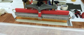
4. Tool holder (Fig. 2). Serves to secure the cutting tool. Often has a mechanism for retracting the cutter when idling to prevent damage to it.
Figure 2. Planer tool holder.
Figure 2. Planer tool holder.
5. Caliper (Fig. 3). The caliper is designed to adjust the cutting depth and set the position of the cutter relative to the workpiece. It is capable of adjusting the position of the cutting tool in height, and can also rotate around the feed axis to process surfaces that are not in a horizontal plane.
Figure 3. Cross planer support.
Figure 3. Cross planer support.
6. Slider. Carries out the main labor movement. Moves on guides. It is driven by an electric motor through a rocker-crank transmission or using hydraulics.
7. Horizontal guides. The slider moves along them.
8. Bed. Planer base. All components and mechanisms of the machine are fixed to the bed.
9. Cross member. It is a design that provides lateral and vertical movement of the table. Includes guides, a vertical feed screw and a connecting kinematic chain for interaction with the slider when automatically adjusting the feed.
Types of metal planing machines
Classification of metal planing machines according to processing technology:
- For longitudinal planing. The table with the part moves relative to the cutter.
- For cross planing. The cutting part moves above the work table on which the part is fixed.
By type of drive:
- hydraulic - moving mechanisms move or rotate at a constant speed;
- crank-crank - the units move in accordance with the settings of the rocker mechanism, that is, the speed can be selected for a specific processing technology.
According to the method of influencing the workpiece:
- lingering - used to remove surface layers (horizontal, vertical or a combination of the first two options)
- shaped-planing - designed to create complex curved surfaces;
- slotting - used to create holes and grooves when moving the cutting tool exclusively along the vertical axis.
Types of planing units
After analyzing the geometric dimensions of the workpiece, as well as the properties of the metal from which it is made, the surface finishing is carried out on a longitudinal or transverse planing unit.
The fundamental difference between these metal cutting machines is determined by the method of moving the cutter. A table moves on the longitudinal planing unit, with the workpiece fixed on it.
Large blanks are processed in this way. When cross planing is performed, the cutter moves and the workpiece is fixed on the table. This method is used when processing medium-sized parts. In each specific case, cutters of the appropriate configuration are selected.
The same class of metal processing equipment includes slotting, broaching and shaped-planing mechanisms.
Using cutters of various shapes, such machines perform operations of selecting recesses and grooves, turning channels and cutting holes.
One of the features of a metal planer is the number of cutting tools installed.
IMPORTANT TO KNOW: Types of drilling and filler machines
Some models are designed for simultaneous fastening of several cutters at once.
The following machine models are produced according to these parameters:
- one-sided;
- double sided;
- four-sided.
The more cutting tools installed on a planer-type device, the higher its productivity.
Construction of a longitudinal planing unit
As prescribed by the technical characteristics, longitudinal planing machines are used for processing surfaces on body and asymmetrical parts cast from cast iron or alloys of non-ferrous and ferrous metals.
The dimensions of the workpiece being processed are determined by the technical capabilities of the planing unit. The initial workpiece to be processed is placed on the table.
The table is capable of performing reciprocating movements. In this case, the cutter fixed in the support remains motionless.
When the table is idling, the support moves to the side, allowing the table to move freely to its starting point.
This complex movement allows you to process large workpieces with several cutters at once.
A longitudinal planing machine for the production of metal products is composed of a frame, a table, supports, a cross member, electrical equipment, a lubrication system and other components.
Each model has its own length and width of the working surface of the table. A common element for all models is the control panel.
When processing parts with complex geometric dimensions, several cutting tools can be installed on the support. This technique reduces the time for processing the product.
Design of a cross-planing unit
A cross-type metal planing machine is installed in production lines where small and medium-sized parts are processed.
The unit is used for planing horizontal, vertical and inclined surfaces.
As in any metalworking machine, the main elements of the cross-planing unit are the bed and the base.
IMPORTANT TO KNOW: Review of radial drilling machines
All components and devices that are designed to ensure fastening and movement of the corresponding elements are attached to this support. The part is fixed on the table at the specified coordinates.
The support, with the cutter fixed in it, is given movement within certain limits.
In the process of metal processing, parts assemblies and structural elements perform complex movements, the purpose of which is to carry out a given program.
The planing unit for metal of the cross type can operate under manual control or according to a given program.
The main one is the reciprocating movement of the slider on which the cutting tool is attached.
Auxiliary is the movement of the table on which the workpiece is fixed. The speed of movement of the slider is controlled using a special gearbox, like in a car.
Before processing any part, all mechanical components of the unit must be lubricated with machine oil.
How to choose a planing machine
Criterias of choice:
- desktop area;
- installed engine power;
- speed of movement of the cutter relative to the workpiece;
- available cutting methods;
- table configuration;
- possibility of positioning the cutter: angle of inclination, trajectory of movement;
- degree of protection of the housing from dust and moisture;
- maximum permissible weight of processed parts;
- manufacturer, warranty period, availability of additional options to expand functionality.
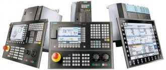
Equipment configuration (Photo: Instagram / kubanzheldormash)
Advantages and disadvantages
Advantages of planing machines:
- versatility of application - processing of various types of metals;
- selection of optimal cutting speed;
- wide selection of cutting tools;
- the possibility of roughing or finishing to obtain the desired level of surface roughness;
- high strength of the body, capable of withstanding increased loads from the cutting tool and the weight of the part;
- convenient control;
- formation of surfaces of complex shape;
- high reliability of installed components and assemblies.
Flaws:
- loss of time moving the cutter relative to the workpiece;
- inertia of moving mechanisms;
- high level of vibrations;
- engine noise;
- the difficulty of obtaining high engine speeds under load or at idle in a short period of time.
Cost and manufacturers
In Russia, machines are produced at the following enterprises:
- Sverdlovsk Machine-Building Plant LLC (SMZ);
- Ryazan Machine Tool Plant LLC (RSZ);
- OJSC "Orenburg Machine Tool Plant" (OSZ);
- OJSC "Astrakhan Machine Tool Plant" (ASZ);
- Lipetsk Machine Tool Company LLC;
- Verkhnevolozhsk Machine Tool Plant.
Cost of machines, depending on their types:
- slotting - from 100 thousand rubles;
- compact - from 35 thousand rubles;
- combined - from 600 thousand rubles;
- transverse - from 65 thousand rubles;
- industrial longitudinal planing machines - from 7 million rubles.
Slotting and planing machine (Photo: Instagram / krasnyi_mehanik_)
Longitudinal planing machines. Single column longitudinal planing machines.
Section: LIBRARY OF TECHNICAL LITERATURE Short path https://bibt.ru <<Previous page Table of contents of the book Next page>>Slitting machines, mainly used in single and small-scale production, as well as in repair shops, are designed for processing flat surfaces on workpieces that are either impossible or inconvenient to process on milling machines.
The workpiece to be processed is fixed on the table of a machine that performs a reciprocating movement. Chips are removed by a stationary cutter (or cutters) only during the working stroke of the table - forward stroke. The cutter feeds for every double stroke of the table.
Longitudinal planing machines can process large-sized parts, the maximum planing length is 2–12.5 m, the maximum width is 0.6–5 mm; the lifting height of the cross member (traverse) is 0.7–4.5 m.
The main components of the longitudinal planing machine are: bed 1 (Fig. 8), table 2, traverse (cross member) 3, vertical supports 4, portal 5, feed box 7 vertical and side supports, side stand 6.
Rice. 8. Longitudinal planing machine:
1 - bed, 2 - table, 3 - traverse, 4 - vertical supports, 5 - portal, 6 - side stand, 7 - feed box
Depending on the design of the traverse, a distinction is made between two-post machines, in which the traverse is supported by two posts, and single-post machines.
The bed of a double-column longitudinal planing machine is a cast iron box-section with two, and in heavy machines with three, longitudinal guides of a flat and V-shaped profile. Machines with long planing lengths have a frame made up of sections held together with bolts during installation. A box-shaped table with internal stiffeners moves back and forth along the bed guides. The working surface of the table has T-shaped grooves and locking holes for reliable engagement of the workpiece being processed.
Single-column longitudinal planing machines are used for processing workpieces of large parts, in which the dimensions of the processed surfaces correspond to the characteristics of the machine, and the overall dimensions do not allow processing on a two-column machine of suitable sizes, for example, workpieces of long and wide parts (beds, etc.) hanging from one side of the table and do not require processing along the entire width. Otherwise, single column planers can be used for all normal planing jobs.
The machine portal consists of two racks, attached at the bottom to the planes of the bed, and connected at the top by a beam. The cross member and the side support carriage can move along the construction guides. The rack contains a weight that balances the side support. The crossbar lifting mechanism is mounted in the racks and the connecting beam.
The cross member is a cast-iron box-section beam, reinforced in the middle with a protrusion and ribs. The crossbar contains two vertical calipers, a caliper feed box, a duplicate control box and a clamping mechanism.
Domestic machine tool factories currently produce many modern single-column and double-column longitudinal planing machines, which make it possible to process parts up to 5000 mm wide, up to 3900 mm high and up to 15,000 mm long from various materials.
Modern longitudinal planing machines are equipped not only with planing supports, but also with grinding and milling heads.
Longitudinal planing machines with grinding heads allow planing and grinding of workpiece parts from one installation and, therefore, obtaining finished surfaces of high cleanliness and accuracy on the machine.
Longitudinal planing machines with milling and milling-boring heads are intended for planing, milling and boring large-sized workpieces. Milling heads can be mounted either on the crossbar or on the machine stand. Crossbar-mounted heads typically receive feed across the table, while side-mounted heads typically receive vertical positioning movements along the rack.
Pit longitudinal planing machines are used for planing the upper horizontal and inclined planes of workpieces of high parts (for example, rolling mill beds). The workpiece being processed is installed on a plate located in a pit, and the machine portal, which carries a cross member with supports, is given a working reciprocating motion. The stroke length of the portal of such machines can reach 12 m.
Skip to navigation
DIY making
Step-by-step creation of a planing machine:
- A drawing, detailing, and cost estimate are created.
- All necessary materials are purchased.
- A supporting frame is made of steel beams, the walls are sheathed with steel sheets.
- The work surface is attached.
- Guides are installed.
- The frame and slider are attached.
- A vice and support are mounted.
- The electric motor is installed, the wiring is laid.
- The motor shaft is connected by a belt drive to the flywheel on which the workpiece is mounted.
- If necessary, a tube with coolant is supplied, as well as a bath to drain its excess into the sewer.
- The correct assembly is checked and tested at design loads.
- Equipment adjustment.
Equipment operation
When using machines, you must follow a number of rules:
- Before carrying out work, you need to make sure that the cutter and the workpiece are securely fastened;
- to prevent overheating of the working tool, a stable supply of lubricating or cooling liquids is required;
- moving parts must be in protective covers;
- It is not allowed to process parts whose dimensions or weight exceed the technical requirements of the machine manufacturer;
- It is prohibited to start work until a stable speed has been reached;
- periodic inspections and maintenance are required;
- maintenance of mechanisms clean is required;
- To avoid short circuits in the supply circuits, it is necessary to ensure an optimal level of humidity in the room.
Some devices are equipped with fasteners for simultaneous fixation of several incisors. This allows processing of complex surfaces with high productivity, since time is not wasted on rearranging cutting tools. There are one-, two- or four-sided fastenings.