Tractor plow
A plow is an agricultural machine designed for plowing (the main type of soil cultivation). During plowing, the working parts of the plow crumble layers of soil, wrap them and dump them at the bottom of the formed furrow. At the same time, all stubble residues and weeds are embedded deep into the soil. Plowing is carried out to a given depth (from 18 to 35 cm) within certain agrotechnical periods.
Plow classification
The classification of arable units is carried out according to the following criteria:
- By purpose:
- General purpose plows equipped with working bodies having a standard working width (35 cm). They are intended for processing old arable soils for sowing industrial, vegetable and grain crops.
- Special purpose arable units. These include planting plows PPN-50 and garden plows PS-4-30; for processing rocky soils PKU-4-35; shrub-marsh PBN-75 and PBN-100A; for vineyards PPU-50A; longline PTN-40 and PTN-3-40 for plowing chestnut and solonetz soils.
- By type of connection to the tractor:
- Trailed
- Mounted
- Semi-mounted
- By type of working body:
- Disk
- Ploughshares
- By number of buildings:
- One (horse)
- Multi-hull (PON-2-30, PLN-3-35, PTK-9-35)
- According to the technology of work execution:
- For smooth (spring) plowing
- For fall plowing (fall plowing)
Plow dimensions for walk-behind tractor
The rotary plow is characterized by the presence of three structural planes: the lower horizontal plane of the skid, the side vertical plane of the skid and the front moldboard plane. If, after removing the ploughshare and moldboard, the plow is placed on a horizontal table, pushed close to the wall, and its side surface is pressed against the vertical wall, then the surface of the table will coincide with the lower horizontal plane of the skid, and the vertical wall with the side vertical plane of the skid.
- The first condition for a good plow is the location of the lower cutting edge of the installed share 10...20 mm below the lower horizontal plane of the skid.
- The second condition for a good plow is that the side cutting edge of the installed plowshare forms a straight line with the side cutting edge of the moldboard, and both of them should protrude 10mm beyond the side vertical plane of the skid.
- The third condition for a good plow is that the front working surface of the ploughshare meets the moldboard in the same plane and without a gap. They should not have protruding fasteners, but should be polished and shiny like a mirror.
Upon completion of work with the plow, it is recommended to clean the polished surfaces from soil, pour in machine oil or lubricate with Litol-24 and rub with a rag. This will protect polished surfaces from corrosion.
The fourth condition for a good plow is a flat back side of the ploughshare, making an angle of 15...20 degrees with the flat surface of the plow installation, equal to the rear angle of the installed ploughshare.
The side cutting edges of the plowshare and blade must also have rear angles of 10...20 degrees with the side plane of the furrow, and the side cutting edge of the blade can be rounded.
General structure (diagram) of a plowshare plow
The arable unit consists of auxiliary elements and working parts mounted on a common frame. Auxiliary elements are designed to facilitate the work. They include support wheels (one or two), furrow wheels (for semi-mounted and trailed plows), a tillage depth adjustment mechanism, a trailing device or a hitch mechanism. The working parts include a knife, a skimmer with a subsoiler and the main body.
Working bodies
The knife is used to cut a vertical layer of soil, facilitating the entry of the body into the ground. It helps level the sulcus wall. General-purpose arable units are equipped with disc-type knives. Special plows used for cultivating heavy soils are equipped with handle-type knives.
The main body of the plow is designed to remove the soil layer, crumble it, wrap it and lay it on the bottom of the furrow. Its device includes a ploughshare, a blade and a field board mounted on a stand. The ploughshare cuts the soil layer. Plows can be equipped with trapezoidal, chisel-shaped, cut-out, with a cheek or a retractable chisel. The blade wraps the cut layer and drops it to the bottom of the formed furrow. Based on the type of blade, the bodies are divided into:
- Cultural - for the main cultivation of old arable soils;
- Half-screw - for plowing soddy soils;
- Cut-out - for cultivating lands with a thin fertile horizon;
- With a retractable chisel - for processing heavy clay soils and loams;
- With a subsoil paw - for plowing and simultaneous loosening of the subsoil layer of chestnut and podzolic soils;
- Disc - for processing heavy, root-choked trees or waterlogged soils;
- Rotary (rotating) - for preparing soils for crops, the cultivation of which requires high quality processing.
- Combined - for plowing with intensive grinding of the cultivated soil layer;
- Non-mouldboard - for preparing for sowing lands destroyed by wind erosion in arid regions. Plows with such a moldboard are called chisel plows.
The field board ensures the evenness of the plow body, preventing it from turning under the reaction of the soil. The body stand can be low (for processing heavy, abandoned soils) and high (for soft, cultivated soils). They are made by stamping. Each rack has a special saddle for attaching the housing.
The skimmer is designed to cut and crush the top layer of soil. It is designed similarly to the main body, but is smaller in size. Its working width is one third less than that of the main body.
Auxiliary parts
Depending on the type of connection between the arable unit and the tractor, the auxiliary parts have a number of distinctive features.
- A mounted plow has a frame welded from transverse, longitudinal and main hollow beams. Its device includes one support wheel equipped with a screw adjustment mechanism. The cross beam is equipped with an SA-2 automatic coupler, through which the arable unit is mounted on the tractor.
- The frame of semi-mounted plows consists of hinged hollow beams. Their equipment includes two support wheels, a transport mechanism with a pair of pneumatic wheels (field and furrow) and an automatic coupler.
- The design of trailed plows includes a device for connecting to a tractor and three pneumatic wheels: a furrow wheel, located in the area of the first body; field, located in the middle part of the plow and rear.
Instructions: Adjusting the plow PLN 3-35
The PLN 3-35 plow is adjusted on the adjustment platform before use when plowing the field. First you need to install spacers for the support wheel of the plow under the left wheels of the tractor on which we attach the plow. The spacers are installed 20-50 mm less than the depth that we are going to plow.
After this, we lower the plow so that all the shares touch the surface. Then use the plow wheel screw mechanism to place the support wheel on the spacer. Now you need to adjust the plow in the longitudinal and transverse planes.
To do this, level it in the longitudinal plane using the tractor hitch, and in the transverse plane using the central link. The main thing is that the plow is parallel to the surface in both planes. We need to install the braces of the tractor hitch on the front holes of the plow's upper link.
We connect the frame and the upper link using the SA-1 automatic coupler through the openings and nothing else.
Under no circumstances use grooves to fasten them, otherwise the plow will then shake when working.
Depending on how deep you want to plow the soil, adjust the skimmers on the plow. Place the toes of the skimmer shares at a distance of 25 centimeters from the body. There is a cylindrical protrusion on the holder. Insert this tab into one of the blind holes in the skimmer post.
Attachment chains. tractors serve as limiters for the plow. They are secured with screws. In this case, the chains should hang a little. All this is required so that when transporting to the ground the plow does not wobble more than 2 cm. Now close the edge of the skimmer so that its edge of the body is covered by the edge of the skimmer.
Now we need to install the left brace of the tractor canopy between the hinge axles. The distance between them should be 51.5 cm.
Before working on the ground, do not under any circumstances change the length of the brace that we have already adjusted.
Before starting work, we need to set the plowing depth in front to 2/3 of that previously set on the support wheel. Once we have completed the first furrow, we complete the setting of the PLN 3-35. Make sure the frame remains parallel to the surface. Make sure that all plow bodies plow the soil to the same depth.
Make sure that all plant residues are thoroughly ground. If the left side is lower than the right, reduce the attachment brace. If the left side is higher than the right, on the contrary, increase the canopy brace. If the rear plow body plows deeper or shallower than the front one, then the upper link needs to be lengthened or shortened. And lastly: if you plow the ground with a power regulator, you don’t have to use the support wheel, since the plowing depth control will be automatic during operation.
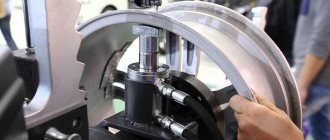
Connection to tractor
To attach a trailed plow, the tractor has a special linkage to which the coupling device of the plowing unit is attached. Mounted and semi-mounted arable units are connected to the tractor via an automatic coupler, consisting of a frame and a lock. The lock, made of two channels inclined at an angle of 65° to each other, is securely fixed with a bolt on a brace welded to the plow frame. The frame is fixed with a pin to the lower arms of the tractor hitch mechanism and with the help of a cheek to the upper link. The lock and frame are supported by a special pawl connected to the cabin by a cable. This allows you to unhook the plow without leaving the cab. The connection of mounted plows to the tractor is usually carried out using a two-point connection. Semi-mounted, wide-cut multi-furrow plows are mounted using a three-point system.
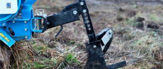
How to install a plow on a walk-behind tractor
Before you start setting up the plow, you need to prepare the walk-behind tractor itself and install the plow on the walk-behind tractor. To do this, the walk-behind tractor is placed at the work site, the wheels with rubber tires are removed and steel lug wheels are installed. This is done in order to reduce the slipping of the walk-behind tractor when plowing due to soil resistance.
After this, they begin to attach the existing walk-behind plow to the attachment. The fastening nuts should not be fully tightened in order to be able to adjust the unit. Then the unit is fixed to the mounting bracket of the walk-behind tractor with two steel pins. Once these operations are completed, the plow adjustment operation can begin.
Features of special-purpose plows
Special-purpose plows are equipped with working bodies of a special design, allowing soil cultivation under specific conditions.
- Shrub-marsh plow PBN-75/PBN-100A. Its device includes one housing with a working width of 75 or 100 cm, disk; flat, equipped with a support ski, or a cutting knife, a linkage mechanism and a support wheel. Used for plowing drained mineral soils and peatlands, previously cleared of small shrubs from pastures and meadows.
- Reinforced plows for preparing for sowing rocky soils. They are equipped with automatic (PKU-4-35) or hydropneumatic (PGP-7-40, PKG-5-40) fuses. When hitting a tree root or stone remaining in the ground, the fuse is triggered and the body is pulled out of the soil. Having passed it, under the influence of the traction force of the tractor, the body is again buried in the ground.
- Longline plows PTN-40 and PTN-3-40. They are used when necessary to increase the depth of the subsoil horizon when cultivating depleted soils (podzolic and solonetzic), as well as to prepare land for planting garden trees, vineyards and cotton. In three-tier plowing, the first body cuts the top layer and dumps it to the bottom. The second body lifts the lower layer along with the upper layer laid on it, but does not wrap it around, but moves it to the side, forming a furrow. The second layer of soil removed by the rear body is dumped onto it. Double-tier plowing can be done in two ways. In the first case, the top layer falls onto the surface of the plowed area, and the bottom and middle layers are loosened and mixed. In the second case, the middle and lower horizons are brought to the surface, and the upper one is buried at a given depth.
- Single body plow. Used for cultivating light fertile soils in garden plots.
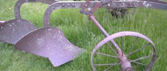
Plow PLN 5-35: description, characteristics and use
PLN 5-35 is a five-furrow mounted plowshare plow, whose task is to plow soil that is not littered with flagstones, stones and other debris for grain and industrial varieties. The second number in the name, “35,” means the width of the soil plowed with one body. With a ground coverage width of 350 mm per body, the plow plows to a depth of up to 300 mm.
The plow is rated for resistivity up to 0.12 MPa and ground hardness up to 4 MPa with absolute humidity up to 25 percent or so. Works at a slope of 8 degrees. The depth of entry into the ground is set by a screw on the support wheel. The support wheel forms part of the plow along with the bodies, frame, skimmers and braces.
Productivity of the Plow PLN 5-35
The productivity of such a unit is up to 1.57 ha/h per 1 hour of main time. Plows of this brand are equipped by manufacturers with high-speed bodies. Operating speed - from 8 to 12 km/h. PLN 3-35 is mounted on tractors with a power of 30 kN, such as T-150K and T-150.
As an option, we can consider the image and description of the PLN 5-35 plow produced.
Plow frame PLN 5-35
The plow frame consists of a main and additional (longitudinal) beams, cut in the shape of a pipe. The plow body holders are attached to these beams. The working parts of the plow are the bodies and skimmers.
Operating principle: skimmers dig into the ground, lift the soil, tip it over and throw it onto the bottom of the previously plowed furrow. It is possible that the client can agree on the manufacture of skimmers to order.
If the plow bodies work with the help of angles, and not with skimmers, as in the previous version, the anglers cut off a ball of earth, which lifts the body, and drops it to the bottom of the previous furrow. The body places a layer of soil on top of the existing layer, and therefore, thanks to the use of weeds, weeds are completely removed, plant residues are covered, and the soil crushing we need is achieved.
When operating it, it is necessary to reduce the central thrust so that the gap under the first body is at least 250 mm. After this, adjust the length of the hinged limiter chains so that the ends of the lower links dangle no more than 20 mm to the right and left sides.
Types of plows
Among the loosening devices, depending on the nature of soil cultivation, there are the following types of plows:
- Dump
- Dumpless
- Special
The first two categories relate to agricultural devices and are used for basic soil cultivation. The devices differ from each other in the nature of loosening, where the first ones provide plowing with the rotation of the soil layer, and the second (non-moldboard) cultivate the fertile layer without turning it over.
Plow body
Working paw of a bladeless flat cutter
Chisel rippers
The category of special plows includes devices designed for reclamation operations or wandering in the development of areas after logging. The working bodies of such devices correspond to the nature of the tasks performed. The example below shows a universal device that provides, during readjustment: uprooting, cutting fire furrows, hilling.
Working parts of a universal forestry plow
Special plows
This category of devices includes plows intended not so much for cultivating the soil, but for performing technological operations related to the formation of relief or soil cleansing, such as:
- uprooting roots and stumps
- hilling crops
- cutting irrigation, planting and fire furrows
Universal mounted forestry plow
In the design of these devices, there is no specific underlying system and nature of the work of the working body and processing. The cutting and loosening organs of special plows have a different appearance, with a shape and design that meets the specifics of the work being performed.
Rooter
PKL-70D forest uprooter-furrow cutter
Rooter
Assembling a homemade product
After all the elements of the future plow are ready, to complete the work you will need a 0.5 x 0.5 m metal sheet and a welding inverter. The plow parts are welded to the workpiece with certain angular dimensions: the plow and the side shield. The moldboard part is applied to the surface of the ploughshare.
If the angles are calculated incorrectly, the plow blade is brought to the correct shape using a hammer, and then it is attached to the back of the ploughshare and to the side shield by welding. Afterwards, an expansion bar and a base in the form of a plate are installed on the shield, on which the corners for the ploughshare are attached.
The assembled home-made product for tillage is carefully inspected for all welded joints and, if there are no defects, all seams are finally welded.
Upon completion of the assembly and welding work, the auxiliary sheet is removed using an angle grinder or available metalworking tools. Places of welded joints require mandatory cleaning, and the blade and ploughshare are treated with sandpaper for standard roughness.
To set the product in motion, it must be attached to a walk-behind tractor. A similar design can be used when constructing a plow for mini tractors. The difference will only be in overall and geometric dimensions, depending on what type of mini tractor the product is designed for.
Building a plow with your own hands, in addition to acquiring certain skills, will significantly help reduce the labor intensity when working on your site.
Moldless plows
The category of moldless plows includes subsoilers-flat-cutters and chisel rippers. Plowing with such devices is characterized by deep loosening of the fertile layer with minimal disruption of its upper part. This treatment helps protect the soil from wind erosion and drying out.
Mounted flat cutter KPG-2-150
The working parts of the flat cutter are made in the form of powerful pointed paws, ensuring loosening over the entire thickness of the horizon without disturbing the surface. Chisel plows are equipped with chisel-shaped rippers, which allow, together with effective loosening, at maximum depth, to destroy the compacted layer of the arable sole, ensuring the deepening of the arable layer and the supply of moisture from the lower layers.
Mounted chisel PCHN-4
The majority of models of moldless rippers require the creation of a significant traction force from the tractor for the unit to operate. Among the non-mouldboard devices on the market, the lowest traction force, as part of such an arable unit, requires a tractor of at least 2nd traction class and higher.
Trailed chisel wide-cut subsoiler
It should also be noted that there are models of plows with universal use, where, when converting working bodies, the ripper device can be used as a moldboard plow and a moldboardless ripper. An example of such a land-cultivating mounted machine is the high-speed combined universal plow - PSKu-5(6), which in the moldboard mode is equipped with screw blades, and in the non-mouldboard mode the blades are dismantled.
Mounted PSKu-5
Brands of flat cutters
Decoding the brands of flat cutters
KPG-2-150 cultivator flat-cutter deep-ripper with 2 working parts, with the grip of one lancet share 150 cm PGN-5 mounted flat-cutter-subsoiler with 5 cutting paws PGP-7 trailed flat-cutter-subsoiler with 7 cutting tines
Moldboard-less flat cutter ripper PGN 5
| Brands of flat cutters | Working width, m/productivity, ha per hour | Required traction force of the tractor, t.p. |
| KPG-250 | 2,5/1,08-1,35 | 3-4 |
| KPG-2-150 | 3.2/ up to 3 | 3-4 |
| PGN-3 | 3,2/3 | 3-4 |
| PGN-5 | 5,3/5,3 | 5-6 |
| PGN-7 | 7,4/7,4 | 5-6 |
| GGP-7 | 7,4/7,4 | 5-6 |
Chisel brands
Examples of deciphering the abbreviation of subsoiler chisels:
PCHN-4.5 mounted chisel plow with a working width of 4.5 m PCHG-3 chisel deep-ripper plow with a working reach of 3 m GCh-4 chisel deep-ripper with a working reach of 4 m PCH-3/1-6 – chisel plow with a working reach of 3 m, one row of working tools with 6 rippers PCH-4.5/2-9 – chisel plow with a grip of 4.5 m, two rows of working tools with 9 rippers
| Brands of chisel subsoilers | Working width, m/productivity, ha per hour | Required traction force of the tractor, t.p. |
| GRZ-1.5 | 1,5/0,8-1,2 | 2 |
| PCH-2/1-4 | 2/1,5 | 2-3 |
| PCH-2,3 | 2,3/1,5 | 2-3 |
| PCHN-2.5 | 2,5/1,8 | 2-3 |
| PCh-2.5/2-5 | 2,5/1,8 | 3-4 |
| PCHG-3 | 3/1,5-3 | 3 |
| PCH-3/1-6 | 3/1,5-3 | 3-4 |
| PCH-3.5 | 3,5/2,5 | 4-5 |
| PCh-3.5/2-7 | 3,5/2,5 | 4-5 |
| PCH-4/2-8 | 4/3-4 | 5 |
| PCHG-4.2 | 4,2/2-4,2 | 5 |
| PCH-4.5 | 4,5/3,5 | 5-6 |
| PCH-4.5/2-9 | 4,5/3,5 | 5-6 |
| GC-4 | 4/3,2-4,8 | 5-6 |
| PCHG-5.4 | 5,4/2,5-5,4 | 5-6 |
Adjusting the plow on a walk-behind tractor
Adjustment of the plow on a walk-behind tractor should be carried out with maximum adherence to the rules, because the quality of plowing directly depends on it. It is carried out in the following steps.
First, the wheels of the walk-behind tractor are placed on stands specially prepared for this purpose and it is balanced. The height of these stands directly determines the depth of plowing (the height of stands for plowing frozen soil should be no more than 20-25 cm, for spring soil - 15-20 cm).
After this, the adjusting bolts are used to set the angle of inclination of the plow so that its “heel” is parallel to the surface of the ground.
After securing the plow, the walk-behind tractor is removed from the stands and placed on the ground. The steering wheel is set so that the control handles are at the height of the plowman’s belt.
The last step in adjusting the plow is to evaluate whether it is set correctly. To do this, control plowing is carried out in the form of two to three furrows, measuring the depth of cut and the quality of the soil dump, as well as the distance between the furrows. If the distance between the furrows exceeds 10 cm, or they overlap each other, the adjustment must be repeated.
Operating a moldboard plow
Plows with moldboard bodies have found the widest application in our latitudes. Such a plow provides plowing of the field with full or partial rotation, creating loosening of the formation. A moldboard plow is an indispensable unit on the field, which is capable of embedding crop residues to a sufficient depth.
Among the known ones, this is the most environmentally friendly of all known methods of weed control, successfully replacing even the use of chemicals to control weeds, the harm from which today is considered exorbitant in comparison with the benefits. Also, during plowing with a moldboard plow, larvae of insects - field pests, and spores of various crop diseases are destroyed. And all this without the use of herbicides.
It is worth adding that from the point of view of some experts, the use of a moldboard plow does not seem so clear-cut. The arguments include the deterioration of the fertile soil layer and its compaction, and the need to keep the land fallow. As an alternative, non-traditional methods of tillage are offered - gentle, minimal, no-moldboard. However, herbicide-free cultivation of crops without a moldboard plow is currently not possible, which means it will continue to be used.