A caliper is a kind of ruler that has been modernized to increase the accuracy of readings. Due to the ease of use of this tool, it has found wide application in many areas of industry, in auto repair shops and in making crafts at home. With its help, the exact dimensions of parts, their depth, hole diameters and dimensions of recesses, components and distances between them are determined.
Once I was very surprised in the automotive market when I was selecting a bearing with a certain internal diameter. What was needed was a bearing that fits tightly on the axle; for this, it is heated before landing. The seller did not know how to measure the inner diameter of the bearing, although a caliper was nearby. I had to show him how to do it and choose the right size myself.
We were taught how to use a caliper back in school, during labor lessons. But over time, if you rarely use it, knowledge is forgotten. In the article we will consider what types of this instrument there are, various options for its execution, and how to read readings.
Classification of measuring instruments
Ammeter.
Measuring current strength Eryutkin E.S. There are several types of measuring instruments, distinguished by certain parameters.
By type of work.
Types of measuring tools
The following types of tools are distinguished:
- building;
- locksmith;
- carpentry
Most of the tools used in measuring operations are universal. Therefore, this classification is very conditional.
According to the material of manufacture. Measuring instruments can be made from the following materials:
Marking and measuring tools
- metal;
- wood;
- plastic.
Any tool can be combined, that is, made from several materials, for example, metal and wood.
By method of use. According to this parameter, hand tools are distinguished, mechanical and automatic.
According to design features. The design of the instrument used for measuring work can be simple or complex.
This classification helps ensure that the tool is used and stored correctly.
Equipment operating conditions
API sn
Preserving the functionality of devices allows periodic maintenance and checks of their condition. Measuring instruments with complex design features are most susceptible to failure.
Each device comes with an instruction manual, which you should read before using it. The instructions set out all the operating rules that are relevant specifically for this model.
Automatic and electronic models of measuring machines are sensitive to temperature and air humidity. Equipment that uses a non-contact measurement method reacts especially sharply to them.
It is equally important to provide the instrument with decent storage conditions. Tools made of wood and metal are sensitive to moisture
And plastic can deform under direct sunlight and when exposed to high temperatures. Therefore, all tools should be stored in cases or boxes in a dry room.
Compliance with these rules will ensure the quality and accuracy of measurements, and will also help extend the life of the instruments.
Related video: Measuring tool
Selection of questions
- Mikhail, Lipetsk – What discs should I use for cutting metal?
- Ivan, Moscow - What is the GOST for rolled sheet steel?
- Maxim, Tver – Which racks for storing rolled metal products are better?
- Vladimir, Novosibirsk – What does ultrasonic processing of metals without the use of abrasives mean?
- Valery, Moscow – How to forge a knife from a bearing with your own hands?
- Stanislav, Voronezh - What equipment is used for the production of galvanized steel air ducts?
Measurement errors
Drill attachment for polishing, or polishing machine
Even if you use the most expensive measuring instrument, the possibility of error cannot be ruled out. The main reasons leading to measurement inaccuracies are inability to use the tool, the use of a damaged tool (including one with a knocked-off zero mark on the scale), contamination of the working surfaces of the tool and the object being measured, measurement of a heated or cooled part
Therefore, it is very important to store measuring instruments in protective cases, remove dirt from them in a timely manner, and check that the initial mark on the scale corresponds to zero. The standard temperature at which measurements of parts (especially metal ones) are carried out is considered to be +20°C
Another way to reduce the error is to take a series of measurements of one parameter and calculate the arithmetic mean value. This practice is widely used when using inexpensive instruments, but it also does not hurt when measuring with professional models, the error of which is extremely small.
How to take measurements, checking the serviceability of a caliper
Before taking measurements, you should check the technical condition of the instrument. No traces of rust, dents or scratches are allowed on its working areas. Distortion of the boom jaws is not allowed. The numbers are easy to read, and the movement of the moving elements is smooth, without jamming or jerking.
How to take measurements:
- When measuring the size of a part from the outside, use the edges of the caliper to clamp it tightly without gaps. It is located parallel to the plane of the object being measured.
- To measure the diameters of round holes, jaws are placed at the most distant points. In this case, the frame passes through the axis of the hole, perpendicular to it.
- If a depth gauge is used, then the caliper is installed at the edge of the hole, the tool is positioned perpendicular to the plane of the part and the depth gauge ruler is pulled out until it stops at the bottom.
- After this, the readings are read.
How to check a caliper
When starting to work with a caliper, you should check the correctness of its readings. To do this, bring its edges together, while the zero of the main scale and the vernier must be aligned. And the last vernier mark should point to the 39 mm mark of the main scale (an example is shown in the photo, the marks are marked in red). I would like to draw your attention to the fact that depending on the design and division price, the length of the vernier may vary. In our example, it is 39 mm, but there are 19 mm with a division value of 0.1 mm, respectively, and the last vernier mark will indicate the number 19.
The number of divisions of the vernier is determined by the accuracy of the caliper: 10 divisions - with an accuracy of 0.1 mm, and 20 - with an accuracy of 0.05 mm.
In some designs, the vernier scale is attached to the frame with screws and has oval holes in these places. This was done to correct the vernier scale if, when checking for the correctness of the readings, the result was unsatisfactory.
Preparing the digital caliper for use
Digital calipers have a “zero” button. Before starting measurements, bring the edges of the device together and press this button. Zero readings are displayed on the screen - the instrument is ready for use. Before starting measurements, similar operations are carried out with dial calipers; the zero is adjusted by a rotating head, which is located at the bottom of the dial.
Scale tools
Measuring metal ruler. Designed to determine the linear dimensions of various workpieces and products with an accuracy not exceeding ±0.5 mm. The ruler is a thin steel strip made of tool carbon steel U7 or U8. On one of the wide sides of this strip, divisions (scale scale) are marked at a distance of 1 mm from each other from left to right. Some rulers have smaller divisions (0.5 mm).
The length of the rulers can be 100, 150, 200, 300, 500, 1000 mm, width – 11-25 mm, thickness – 1-12 mm. At the beginning of the ruler scale there is a mark indicating the division value.
The method of measuring products with a metal ruler is very simple. The ruler is applied to the part being measured parallel to the axis of the product so that the zero division coincides with one of the ends of the part being measured, and then the stroke on which the second end of the part falls is counted. The size of the product will be shown by the division coinciding with its end. To increase the accuracy of measurements, the end faces that serve as the beginning or end of the scales must not have nicks or rollovers and be perpendicular to the longitudinal edge of the ruler from which the strokes begin.
When measuring parts, it is necessary that the ruler fits tightly to the part and is correctly positioned on its plane. When measuring the length of cylindrical parts, it is necessary that the ruler lies exactly along the generatrix of the cylinder, since if the ruler is tilted, the size will be increased. When measuring the internal diameter of a hole in a part, the ruler is positioned so that its edges pass through the center of the part, otherwise the size of the hole will be reduced.
For accurate measurements, it is recommended to rest the end of the ruler against the bar, which is pressed against one side of the part being measured. If this is not possible, then the centimeter division line of the ruler should be placed flush with the edge of the part.
In this case, from the size taken using the ruler, it is necessary to subtract the size of the zero division to the stroke from which the count was made.
Folding meters. Folding meters are rulers designed for linear measurements. A folding meter consists of several short identical rulers (links), hingedly connected to each other. The rulers have millimeter, half-centimeter and centimeter divisions.
The length of folding meters is 1 m and less often – 2 m, the length of the link is 100 mm. Steel meters are made from tool carbon steel grades U7-U8, and sometimes from hard wood. The measurement accuracy of folding meters can be within 1 mm. As the hinge joints wear out and the clarity of the dashed lines decreases, the accuracy of measuring with folding meters decreases. The techniques for using folding meters are similar to the techniques for using metal measuring rulers.
Roulettes. Used for measuring long lengths in cases where great accuracy is not required.
To measure parts and assemblies of short-length machines (up to 2 m), metal tape measures are used, in which the steel tape extends automatically from the metal frame and does not bend when extended. Measurement accuracy ±0.25 – ±0.5 mm.
To measure large lengths, tape measures are used, which are a steel or canvas tape with a length of 2; 5; 10; 15; 20 m or more, placed in a metal or leather case. On tapes up to 5 m long, millimeter divisions are usually applied, and on tapes over 5 m long, centimeter divisions are applied. From a leather or metal case, the tape is pulled out by the free end, and upon completion of work, it is rolled up by rotating the handle in the case.
To mainMEASURING TOOL
Parts are manufactured with various deviations from the nominal dimensions indicated in the drawing, depending on the accuracy. If absolutely precise execution of a size is required, then we encounter the difficulty of accurately measuring this size. Many reasons and circumstances during measurement lead to the fact that the actual size of the part differs from the size shown by the measuring device. The difference between the measurement result and the actual size of the part is called measurement error. The magnitude of this error characterizes the accuracy of the measurement performed. The error in the size of a part during measurement can be positive or negative (the measurement result can be larger or smaller than the actual size of the part). The accuracy of measuring parts depends on the measuring device or measuring instrument used to make the measurements. In addition, the surface cleanliness and temperature of the part also affect the measurement accuracy. To obtain the same measurement conditions, the all-Union standard establishes that measurements should be made at a temperature of +20°C. Depending on the design of the measuring instrument and the method of measurement, measuring instruments and instruments are divided into line, lever-indicator, gauge blocks, instruments for measuring angles and cones, optical and interference. Line instruments include: scale rulers, calipers, depth gauges, height gauges, vernier protractors, micrometers, micrometer depth gauges and gauges. They are called line marks because on one of their parts there are divisions (strokes), and on the other there are marks of the pointer. Lever-indicator instruments include dial and lever type indicators, sensitive micrometers and minimeters. Lever indicator instruments have a fixed scale and a moving arrow that indicates the size of the part being measured. Gauge blocks include plane-parallel gauge blocks and gauges. To measure angles and cones, angle tiles, sine rulers, squares and protractors are used. Optical instruments include: optimeters, microscopes, projection comparators. For measurements using the interference method, sets of special plane-parallel glasses are used. The scale ruler is intended for marking, measuring length, etc. It has scales with millimeter and half-millimeter divisions, so the measurement accuracy is 0.5 mm
.
Scale rulers are made from carbon steel grades U7 or U8. A caliper
is a measuring instrument consisting of two jaws (jaws): one, fixedly connected to a scale ruler (bar), and the other, sliding along the ruler and equipped with a vernier.
There are two types of calipers: with measuring accuracy up to 0.1 mm
(Fig. 23) and with increased accuracy up to 0.02 and 0.05
mm
(Fig. 24), which are used for more accurate external and internal measurements.
The caliper has a depth gauge with a measurement accuracy of up to 0.1 mm
.
A caliper for measuring fractions of a millimeter has a vernier; the scale of such a vernier is divided into ten equal parts and occupies a length equal to nine divisions of the ruler scale, i.e. 9 mm
.
Therefore, one division of the vernier is 0.9 mm
, i.e. it is shorter than each division of the ruler by 0.1
mm
.
If you close the legs of the caliper closely, the zero stroke of the vernier will exactly coincide with the zero stroke of the ruler. The remaining vernier strokes, except for the last one, will not have such a coincidence: the first vernier stroke will not reach the first stroke of the ruler by 0.1 mm
;
the second stroke of the vernier will not reach the second stroke of the ruler by 0.2 mm
, etc. The tenth stroke of the vernier will exactly coincide with the ninth stroke of the ruler.
If you move the frame so that the first stroke of the vernier (not counting the zero) coincides with the first stroke of the ruler, then between the legs of the caliper you will get a gap equal to 0.1 mm
.
If the second stroke coincides with the second stroke of the ruler, the gap between the legs will already be 0.2 mm
, if the third stroke of the vernier coincides with the third stroke of the ruler, the gap will be 0.3
mm
, etc. Consequently, the vernier stroke that exactly coincides with some or a ruler stroke, shows the number of tenths of a millimeter.
A caliper with an accuracy of 0.02 mm
has a vernier, the scale of which is 12
mm
and is divided into 25 equal parts, the scale of the vernier is 12: 25 - 0.48
mm
, and since the ruler has a division value of 0.5
mm
, the reading accuracy will be the difference between the division values of the ruler and the vernier (0.5 - 0.48 = 0.02
mm
).
Vernier depth gauges
(Fig. 25) are used to measure the depths of blind holes, recesses, grooves, grooves, ledges, etc.
If the zero divisions of the vernier and the rod coincide, the measuring end must be in the same plane with the working surface of the depth gauge frame. Vernier depth gauges are manufactured with a vernier reading accuracy of 0.1; 0.02 and 0.05 mm
, and the largest measurable size is 100;
125; 150; 200; 250; 300; 400 and 500 mm
.
The method of measuring with a depth gauge is as follows: the depth gauge is installed with its base on the edges of the hole, and the scale ruler is extended all the way to the bottom of the hole. The count is made in the same way as on a caliper. Micrometer
(Fig. 26) is a more accurate measuring instrument, which is designed to measure external dimensions with an accuracy of 0.01
mm
.
The micrometer consists of: bracket, heel, sleeve, micrometer screw, bushing, ratchet and stopper. The main part on which the micrometer is mounted is the bracket. A fixed heel is pressed into the bracket. Millimeter and half-millimeter divisions are applied along the circumference of the outer diameter of the liner. Inside the sleeve there is a nut into which a micrometer screw is screwed. The micrometer screw has a smooth polished end and a polished measuring plane at the end. The micrometer screw has a thread with a pitch of 0.5 mm
, manufactured according to the second class of accuracy.
A ratchet head is installed in the micrometer screw. For each full revolution of the micrometer screw, the sleeve and screw move 0.5 mm
.
To measure fractions of a millimeter, there are 50 equal divisions on the sleeve. Therefore, turning the sleeve one notch will move the screw 1/50th of a pitch. The measurement accuracy of a micrometer is equal to the pitch of the micrometer screw divided by the number of divisions of the sleeve, i.e. 0.5: 50 = 0.01 mm
.
To ensure uniform pressure of the micrometer screw on the surface being measured, there is a ratchet. The readings are counted as follows: 1 mm
and 0.5
mm
are counted by the number of divisions on the sleeve, and hundredths of a millimeter are determined by the divisions on the sleeve that coincide with the divisions on the sleeve.
Micrometers of the following sizes are used for measurements: from 0 to 25 mm
, from 25 to 50
mm
, from 50 to 75
mm
, from 75 to 100
mm
, etc.
To measure the average diameter of a thread, thread micrometers are used (Fig. 27), which, instead of a smooth heel and spindle, have replaceable inserts corresponding to the thread pitch. Micrometric depth gauge
used to measure depths and heights.
It consists of a moving part of a micrometer, and instead of a bracket it has a support ruler (Fig. 28). The measurement limit of the micrometric depth gauge is 0—25; 0—50; 0—75 and 0—100 mm
depending on the number of replaceable rods.
The division value in a micrometric depth gauge is 0.01 mm
.
Indicators
- a very common measuring instrument.
They are used to measure deviations from a given size, when checking runout and eccentricity, when checking fixtures, machine parts, etc. In FIG. Figure 29 shows a general view of the indicator. It consists of a measuring pin having a worm thread, with which it is engaged with a worm wheel. When the pin is lowered or raised, the worm wheel transmits the rotation of the axis to the pointer. To eliminate the backlash, a wheel is used, which engages with a small gear mounted on the arrow axis and presses it in one direction using a spring; a helical spring presses on the measuring pin in one direction. To set the hand to the zero position, you need to turn the dial in the desired direction. The dial division value is 0.01 mm
.
Goniometers
There are two types: transporter and universal. A protractor protractor consists of a half-disk with a ruler. A movable ruler is attached to the half-disk; in the slot of the half-disk there is a device for micrometric feed of a lever with a vernier. In order to measure the angle of the workpiece, first set the movable ruler to the desired angle along the zero division of the vernier. Next, the micrometric feed screw of the vernier is secured and the protractor is finally adjusted along the vernier using the micrometric screw. The inclinometer readings are taken using a scale on the half-disk and a vernier. First, they notice which stroke of the half-disk scale has passed the zero stroke of the vernier; the numerical value of this stroke will give us the angle in degrees. To determine the number of minutes, note which stroke of the vernier coincides with which stroke of the half-disc. The serial number of this vernier stroke will indicate the number of minutes in the measured angle. This protractor can measure angles from 0 to 180°. A universal goniometer can measure angles from 0 to 320°. The vernier of a universal goniometer is designed so that its divisions are applied from the zero position in both directions (to the right and to the left).
In fig. Figure 30 shows a universal protractor of the Semenov system. Along sector 1, on which the main degree scale is applied, plate 2 moves, on which vernier 3 is fixed. On plate 2, using a holder 4, a square 5 with a fixed ruler 6 is attached. Plate 7 is rigidly attached to sector 1. Despite the fact that the main scale The angle meter is marked on an arc of 130°; however, through various combinations in the installation of the angle meter parts, it is possible to measure angles from 0 to 320°. The counting value on the vernier is 2 minutes. Using the appropriate installation of the tool, we place the sides of the measured angle of the Part between plate 7 and ruler 6 and, using sector 1 and vernier 3, make the necessary measurements. Micrometric shtihmas
used to measure the internal dimensions of parts, holes, grooves, etc. (Fig. 31). It consists of a micrometer screw, a drum, a sleeve with a stopper and a tip. When measuring, the pin is inserted into the hole strictly along its diameter and the tips of the micrometer head are gradually moved apart until they come into contact with the walls of the holes.
The Shtichmas can be used to measure holes with a diameter of 35 mm
and higher.
Feeler gauges
are used to determine the size of the gap between mating parts.
A set of probes consists of plates with a thickness of 0.04 to 2 mm
(20 pcs.), assembled in a holder (Fig. 32).
Thread gauge
(Fig. 33) is a set of plates with precisely applied thread profiles. There are two types of thread gauges - for measuring metric threads and for measuring inch threads.
To check the thread pitch, select a plate whose profile matches the thread of the bolt or nut being checked. The thread gauge plates indicate the pitch or number of threads. Limit gauges and staples
serve to measure the dimensions of holes and shafts within tolerance (Fig. 34).
To measure shafts and external parallel planes, limit brackets are used (Fig. 35). Limit brackets have a pass-through side, the size of which is equal to the largest permissible size.
When checking a hole with a plug, the through side of the plug must have the smallest permissible hole size. The non-go side of the plug has a size that is equal to the largest permissible hole size, the non-go side of the bracket has a size equal to the smallest permissible shaft size. Plugs with the smallest size limit are called receiving plugs and are designated “PR” (through). Plugs with the largest maximum size are called rejection plugs and are designated “NOT” (non-passable). If the hole is made correctly, the through side of the plug gauge should fit into the hole freely under its own weight. The non-passing side of the plug gauge should not fit into the hole. To check threads, thread plug gauges and ring gauges are used (Fig. 36).
Plane-parallel tiles
(Fig. 37) are used to control the exact linear dimensions of measuring instruments and precision parts. The tiles are made from tool alloy steel grades XG and X.
The shape of the tiles is rectangular; the opposite sides of the tiles are measuring surfaces with precise dimensions. Plane-parallel tiles are produced in sets of 9, 10, 32, 42, 87 and 103 pieces. By various combinations of tiles in a large set, any size can be obtained with an interval of 0.001 mm
.
Squares and templates.
To check linear dimensions and angles, the mechanic uses squares.
The accuracy of the parts is checked for the clearance that forms between the square and the part, and a measurement accuracy of up to 0.01 mm
.
The angles are made of steel 20 and subjected to heat treatment - carburization and hardening. Templates are used to check the profile of the workpiece in open, closed and blind places. The essence of the test is as follows: the part being tested is coated with a thin layer of paint (ultramarine or carbon black diluted in mineral oil) and a template is passed over the surface being tested. There will be traces of paint on the template, which is used to determine the surface error. Checking the open area of the profile can be done against the light, without covering the parts with a layer of paint. Previous page
| table of contents | Next page |
How is the diameter of a pipe measured if it is installed?
If the pipe is mounted and the end is not accessible for measurement, then a caliper is applied to the side surface at its widest point. This can only be done if the length of the legs exceeds half the diameter of the pipe.
If the pipeline is for some reason inaccessible for measurements, then the pipe diameter is controlled by copying. To do this, a ruler or an object with known geometric dimensions (for example, boxes) is applied to the pipe and this area is photographed. Further, all measurements and calculations are carried out using photographs. To do this, determine the apparent thickness of the pipe in millimeters and convert the obtained data into real size, taking into account the scale of the survey.
Control of pipe dimensional parameters in production
All pipes supplied for construction or production must be provided with a certificate.
It states:
- nominal dimensions of products,
- regulatory documentation according to which they were manufactured,
- batch number,
- brand of material,
- results of tests and other necessary information.
Markings must be applied to the end of the pipe at a distance of 500 mm from the end. The markings indicate: the name of the manufacturing company, the heat number, the nominal dimensions of the product, the pipe number and the date of its manufacture.
Before using communications on construction sites and in production, they are necessarily subjected to input control with the measurement of their geometric parameters. The length is measured with a tape measure or wire.
The outer diameter of pipe products in production is calculated using a slightly complicated formula. The circumference of the pipe is divided by the number π, and from the result obtained, the double thickness of the measuring tape and 0.2 mm - the fit tolerance - are subtracted.
Permissible deviations of the outer diameter from the declared one for pipes with a diameter of less than 200 mm are equal to 1.5 mm. An ultrasonic pipe measuring unit is used to measure large-diameter products. .
To measure wall thickness in production, a caliper with scale divisions of 0.01 mm is used. The minus tolerance should not exceed 5% of the nominal thickness of the product.
Permissible defectiveness of pipes
The curvature of incoming pipes should not exceed 1.5 mm per meter of length. The total curvature should not be more than 0.15% of its length.
The ovality of the pipe is determined by the ratio of the difference between the largest and smallest diameters to the nominal diameter; ovality for pipes:
- with a wall thickness of less than 20 mm should be no more than 1%,
- with a wall thickness of more than 20 mm - no more than 0.8%.
To solve the question of how to measure pipe ovality,
measure the diameter of the end part with an indicator bracket or bore gauge. Measurements are carried out in two mutually perpendicular planes. Determining the dimensional parameters of communications is not a difficult undertaking and is quite feasible on your own.
Hand construction tools
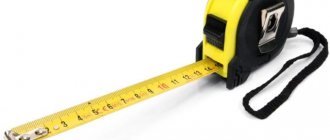
Roulette. The main tool that no builder can do without is a tape measure. A tape measure is something like a ruler, made in the form of a metal tape with divisions equal to 1 mm. The tape is wound into a housing, which can be made of either plastic or metal. The tape can have different widths and lengths.
Of course, a tape measure is universal, required for carrying out measuring work in any field of activity.
Technical characteristics of the roulette
Spirit level (level). This device is used to determine the evenness of horizontal and vertical surfaces. The length of the level can vary from 0.3 m to 2.5 m. The body of the level is made of any lightweight material, such as plastic, and is equipped with several windows.
Through the windows you can see a glass tube partially filled with a special liquid. It is this liquid that allows you to determine the evenness and level of slope of the surface.
Plumb. This is the simplest but indispensable measuring tool that every builder uses. The plumb line represents a rope (twine), at the end of which a metal cone-shaped weight is tied. It is used in cases where it is necessary to control the verticality of work, for example, during brickwork.
Square and fine. A square is made of wood or metal and is used to create right angles. Malka is made from the same materials. Its design consists of a clip and a ruler, fastened together with a hinge. While the square can be used in any area of construction, the square is most often used when installing rafters.
Magnetic square
How to measure the diameter of a pipe that is completely accessible for measurement
If it is necessary to measure the diameter with minimal requirements for accuracy, and the cross-section of the product is completely accessible for measurements, then you can use a regular ruler or tape measure. The measuring instrument is applied at the widest part and the number of divisions is counted. This method allows you to determine the outer diameter with an accuracy of a few millimeters.
To measure small diameter products, use a caliper. To do this, the legs of the tool are applied to the end and pressed firmly, but without force, against the outer walls of the pipe. Using the instrument scale, the diameter is determined with an accuracy of tenths of a millimeter.
To calculate the internal diameter, the thickness of the pipe walls is measured along the cut. Double the wall thickness is subtracted from the outer diameter to obtain the inner diameter.
Steel water pipes are defined by their internal diameter, which is often measured in inches. How to find out the diameter of a pipe in inches if this value is known in centimeters?
To do this, you need to multiply the diameter in centimeters by 0.398. To convert back, the diameter in inches is multiplied by 2.54. That is, the internal diameter of a one-inch pipe is equal to 2.54 cm or 25.4 mm, and, for example, a ½-inch diameter is approximately 12.7 mm.
Measuring disk parameters.
But in order not to measure all the parameters, some of them can be read in the operating instructions for your car or on the spare wheel, if the car is equipped with a “cast” (made of aluminum alloy) full-size spare wheel (the same as all the other wheels that cost by car). To do this, you need to remove the wheel from the trunk and read the inscriptions on the inside of the disk. If your car is equipped with a tire, then you need to remove one wheel from the car if it has alloy wheels. On ordinary “steel” disks, as a rule, the disk parameters are not written on the inside and they are marked according to an internal factory code, which allows you to find out the disk parameters only from an official car dealer or disk manufacturer.
Let's carefully examine the inscriptions on the “alloy” disk from the inside:
1. Disk width 2. Disk diameter
Most alloy disks indicate three parameters, these are “offset”, “disk width” and “disc diameter”. The width of the disk is usually indicated like this: 5.5J x 13 or 5 1/2J x 13, where 5 and 1/2 is the width of the disk - 5.5 inches, and 13 is the diameter of the disk in inches.
3. Disc offset (ET)
Overhang (or as it is also called “disc offset”) is usually indicated by two letters ET or the inscription OFFSET and then there are offset parameters, for example, ET35 or OFFSET 35, where 35 is the offset value in millimeters.
If these parameters are found on the disk, then we only have to find out three parameters: 4. The number of mounting holes for bolts or nuts that secure the disk to the machine
5. The diameter on which these mounting holes are located (PCD)
It is not possible to count the number of holes for bolts problems, usually there are 3, 4, 5 or 6 of them. The diameter at which they are located is sometimes “knocked out” from the inside of the disk, as shown in the figure:
Unfortunately, sometimes it is not very clear where exactly these PCD value numbers are written, since each disk manufacturer may write them in different places or not write them at all. Therefore, we will need a Vernier caliper or a regular ruler. It is necessary to measure the distance between the centers of the far holes located opposite each other, as shown in the figures:
Measurements must be carried out with high accuracy, since there are very close values (for example, 98 and 100 or 110 and 112) and which cannot be used instead of others!
For greater confidence in measurements, we provide a table of the applicability of various PCD values to car brands. For example, if you have a Mercedes car, and the measurement turns out to be 111 mm, then the real value is 112 mm, since Mercedes does not make wheels of either 110 or 111 mm.
98
– Lada, Alfa-Romeo, Citroen, Fiat, Lancia, Peugeot, Seat, Skoda.
100
– Audi, BMW, Cooper, Chevrolet, Chrysler, Citroen, Daewoo, Daihatsu, Fiat, Honda, Hyundai, Jeep, Kia, Mazda, Mitsubishi, Nissan, Opel, Peugeot, Proton, Renault, Rover, Seat, Skoda, Subaru, Suzuki, Toyota, Volkswagen.
108
- Audi, Citroen, Ford, Jaguar, Landrover, Mazda, Peugeot, Renault, Saab, Volvo.
110
- Fiat, Opel, Saab, Alfa-Romeo.
112
- Audi, Chrysler, Ford, MCC-Smart, Mercedes-Benz, Seat, Skoda, Volkswagen.
114.3
- Chevrolet, Chrysler, Citroen, Jeep, Daewoo, Daihatsu, Dodge, Fiat, Ford, Honda, Hyundai, Kia, Lexus, Landrover, Mazda, MCC-Smart, Mitsubishi, Nissan, Peugeot, Renault, Rover, Subaru, Suzuki, Toyota, Volvo.
115
- Chevrolet, Chrysler, Opel.
118
- Citroen, Fiat, Nissan, Opel, Peugeot, Renault.
120
- BMW, Hyundai, Volkswagen.
120.7
- Jaguar.
Trucks and SUVs:
127
— Jeep.
130
- Audi, Citroen, Fiat, Mercedes-Benz, Nissan, Opel, Peugeot, Porsche, Renault, Volkswagen.
139.7
- Jeep, Daihatsu, Ford, GMC, Hyundai, Isuzu, Kia, Lada-Niva, Mazda, Mitsubishi, Nissan, Opel, Ssangyong, Suzuki, Toyota.
150
- Lexus, Toyota.
160
- Ford, Opel, Renault.
161
- Mercedes-Benz, Volkswagen.
165.1
- Landrover.
170
- Opel, Renault.
180
- Ford.
205
- Mercedes-Benz, Volkswagen.
6. Hub Bore Diameter (DIA)
On many disks, the central hole for the hub has a larger diameter than the hub and the disk is centered with a special plastic ring (in the photo the adapter ring is 67.5 mm by 56.1 mm). If the disk is original (or a regular steel one), then there is no adapter ring on it and it centered by the central hole of the disk itself. And it can also be measured with a regular ruler or a caliper.
Measuring tool
Measuring tools are used to measure linear dimensions, gaps and angular deviations, as well as to measure parameters (resistance, voltage, current) of electrical circuits.
Measuring instruments with a reading accuracy of up to 0 01 mm: small micrometer up to 20 mm, micrometer clamp up to 750 mm, micrometer gauge with extensions for measurements up to 750 mm and calipers up to 300 mm. Used to measure shaft diameters and hole diameters.
Measuring tool - In addition to the universal, normal measuring tool: measuring ruler, meter, caliper, micrometer, a special measuring tool is used.
| Measuring diagram of the Romanian valve chamber.| Measuring the Romanian gate (a) and selecting a gate-seat set (b. |
It is proposed to use the measuring tool when assembling a Romanian valve without boring the body.
The measuring tool and templates must be of such a shape and size that when using them, the measuring tool’s hands are outside the working area of the striker.
Measuring instruments and devices that have special cases (factory containers) are stored in the racks of the CIS in these cases and are released in them from the CIS to the IRC of the workshops.
Measuring instruments and instruments are lubricated only with thin oils, technical petroleum jelly, bone oil and lanolin.
| Change in mechanical properties depending on tempering temperature (steel 40. |
In order to stabilize the dimensions, the measuring instrument is tempered with longer holding times.
Measuring tools also wear out only in places that come into contact with the parts during measurement.
A measuring instrument in the form of a compass with arched legs, used for measuring linear dimensions. The taken solution of the caliper legs is compared with a scale ruler. It is used to measure the external dimensions of parts. A drawing tool for laying out small pieces of equal length. Consists of two sliding legs, the opening of which is adjusted with a set screw. At the ends of the legs there are needles secured with clamping screws. Can work with a pencil leg or a drawing pen.
Measuring instruments are made mainly from carbon and alloy tool steels.
The measuring tool and templates must be of such a shape and size that when using them, the measuring tool’s hands are outside the working area of the striker.
It is advisable to strengthen a measuring instrument with a wide tolerance range with hard alloys T15K6, TZOK4 (and in some cases VK8), with mandatory subsequent finishing with abrasive stones. The processing mode is selected depending on the required frequency of the surface, preferably soft.
Design and types of calipers
A little history. Measuring instruments made of bronze, the predecessors of modern calipers, are discovered by archaeologists in excavations from ancient China. In Europe, similar instruments appeared at the beginning of the 17th century; they were made of wood and were not equipped with a vernier, which made them inaccurate.
Vernier calipers of the familiar type made of metal began to be used in England at the end of the 18th century, during the industrial revolution, when more accurate measurements of parts were required. It already had a moving frame with a scale printed on it, which was invented by the mathematician Pedro Nunes and then improved by Pierre Vernier. Based on the names of these scientists, the moving scale began to be called vernier and vernier.
Based on the type of scale, calipers are divided into:
- vernier
- dial
- digital
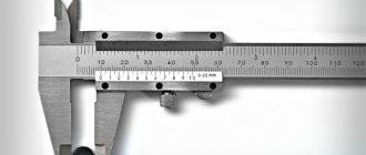
Description of vernier caliper
Basic elements of a caliper
The main parts that make up the device:
- The main thing is the bar with a scale printed on it. Hence the name.
- Frame with a vernier scale, allowing you to read fractions of a millimeter.
- Sponges for external and internal measurements.
- Depth gauge ruler.
- The locking screw securing the frame may be missing in some types.
Structurally, a caliper consists of two rulers superimposed on each other. The photo shows a device that allows you to measure the internal and external dimensions of parts, as well as the depth of the holes in them. Its measurement range is 0-125 mm, accuracy is 0.05 mm, this is indicated to the right of the vernier scale.
Calipers vary in size and, accordingly, limits: 0 - 150 mm, 0 - 500 mm, 500 - 1600 mm, 800 - 2000 mm and others. Accuracy of devices: 0.1 mm, 0.05 mm, 0.02 mm, the latter are close to micrometers in accuracy.
Some types of booms have second scales for reading in inches. They are located on the top of the rod and frame. There are also models that allow you to apply markings to the surface of the workpiece - their edges are specially sharpened and made of hard materials.
Dial calipers
Vernier caliper with dial scale
The design of the dial instrument is similar to that of a vernier instrument, but a round scale is installed on the frame. When reading readings, whole millimeters are viewed along the left edge of the frame, and fractions of a millimeter are viewed along the markings on the dial. This type of caliper is used when high accuracy is required or when it is impossible to use a vernier caliper.
The range of such a device is 0 - 300 mm, division value is 0.01 mm. It allows you to obtain a more reliable measurement result and the process itself is simpler than using a vernier caliper.
The disadvantage of the dial bar is its high cost and limited range (300 mm). The reading device may fail if stored improperly due to exposure to dust and dirt.
Digital calipers
Digital caliper
This meter is very similar to those described earlier. The result of the measurements taken is displayed on a digital screen. It is indispensable if data needs to be obtained quickly and with great reliability. The measurement range is from 0 to 3000 mm, the division value of some specimens is 0.01 mm.
On the frame with the display there are buttons for turning on, setting zero and switching readings in millimeters or inches. Its advantages include the ability to store the results of the latest measurements in memory, high accuracy and speed. All this significantly increases productivity and saves time when carrying out a large number of measurements, for example when rejecting products. The performer does not need to count on the dial; the result is instantly displayed on the screen.
Digital booms are more expensive than those previously discussed with the same characteristics. Power is supplied from a battery, which must be charged or replaced over time. The electronics of such devices are susceptible to the negative effects of temperature and humidity changes.
Vernier scale
To improve measurement accuracy, some instruments are equipped with an auxiliary scale. It is called differently: vernier - in honor of the Portuguese mathematician P. Nuniz, or vernier - in honor of the French scientist P. Vernier, who in 1631 proposed a scale design that is still used today.
The principle of operation of this device is based on the fact that the eye better records the coincidence of divisions of the main and auxiliary scales than determines the mark between divisions. Moreover, the zero value of the vernier indicates an integer part, and the number of the division coinciding with the division of the main scale indicates a fractional part. The use of a vernier allows you to obtain results with an accuracy of tenths to hundredths of a millimeter.
Hole measurement
Measuring imprecise holes. Inaccurate holes are measured using an ordinary (Fig. 134, a) or spring (Fig. 134, b) bore gauge.
Rice. 134. Ordinary (a) and spring (b) bore gauges
To measure the diameter of a hole using this instrument, insert it with your right hand into the hole being measured (Fig. 135). Using the index finger of your left hand, press the sponge of one of its legs against the wall of the hole. Slightly shaking the inside gauge, feel for the smallest opening of its legs, at which the sponge of the second leg touches the wall of the hole.
Fig. 135. Measuring the hole diameter with a bore gauge
Having installed the bore gauge solution, determine its value using a measuring ruler (Fig. 136). The end of the ruler should rest against some machined surface, for example, against the wall of a part of the caliper.
Rice. 136. Determining the value of the bore meter solution using a measuring ruler
The accuracy of measuring the diameter of a hole with a bore gauge, taking into account errors in installing its solution and reading the value of this solution using a ruler, is usually in the range from ±0.2 to ±0.5 mm. Note that even such a low accuracy of measurement with a bore gauge is only possible if it is in good condition. This requires maintenance of the bore gauge, similar to that indicated above when describing the calipers.
The diameters of more precise holes are measured with an ordinary caliper (Fig. 137), and its sharp jaws A and B are used.
Fig. 137. Measuring the diameter of a hole with an ordinary caliper
Measuring precise holes. Precision holes up to 10mm in diameter are checked with the gauges discussed below.
Holes larger than 10 mm in diameter can be measured with a precision caliper using the rounded outer sides of its jaws. To determine the diameter of the hole being measured, it is necessary to add the total length of its tightly pressed jaws to the reading of the caliper, read in the usual way. This length (usually 10 mm) is indicated on the caliper. However, in order to avoid errors, before measuring the hole using the method in question, you should first measure the total length of the caliper jaws, for example, with a micrometer. Using a caliper, you can measure the diameter of only part of the hole located at the end of the part, and you cannot check its cylindricity (for example, the absence of a cone), which in many cases is absolutely necessary.
Precision holes can also be measured using micrometer gauges. On the Ukrainian gambling market, competition between virtual clubs is intensifying every year. The leader in popularity is confidently held by the official Slottoking website, as many say, where you can play for free or for money around the clock. A large selection of entertainment, bonus and loyalty programs, promotions and the opportunity to hit the Jackpot are not the whole list of advantages over competitors. The micrometric pin (Fig. 138, a) consists of a stem 1, which has a tip with a spherical measuring surface A at one end. The movement of the screw corresponding to its full revolutions is counted on the scale of the stem, and the movement corresponding to parts of a revolution is measured on the scale of the drum 2 with a spherical measuring surface B connected to a micrometric screw.
Rice. 138. Stichmas (a) and additional measuring rod (6) to it
To increase the measurement limits of the micrometer gauge, measuring rods (Fig. 138, b) of various lengths, ending in spherical measuring surfaces, can be attached to the end of the stem.
The gauge in question has the same micrometer screw as the micrometer for external measurements, so it can be used to make measurements with an accuracy of 0.01 mm. Counting using a micrometer gauge is carried out in exactly the same way as when using a micrometer.
When measuring holes with a pin, you must carefully ensure that it is installed exactly perpendicular to the axis of the hole being measured. To do this, rest one end of the pin on the surface of the hole, and move the other in the center plane of the hole, feeling for the smallest size, just as is done when measuring hole diameters with a bore gauge.
To check the diameters of precise holes in parts manufactured under conditions of interchangeability, a variety of limit plug gauges and limit gauges are used. Holes of relatively small diameters are checked with limit plug gauges (Fig. 139, a). When checking holes of large diameters, so-called incomplete limit gauges (Fig. 139, b) or limit gauges (Fig. 139, c) are used. One of the tools shown in Fig. 139, in, is passable, and the other is impassable.
Rice. 139. Limit plug gauges (a, b) and limit gauges (c)
How to determine hole diameter
Carrying out measurements in any field of technology involves the use of special tools and devices. They differ from each other in the method of application, measurement accuracy and the area in which they can be used. A special place in measurements is occupied by the determination of holes.
You will need
In the simplest case, when greater measurement accuracy is not essential, use a measuring ruler to determine the diameter of the hole. Place the tool against the hole at the level of its diameter and count the number of divisions (centimeters and millimeters) that fit in the hole on this line. For most household measurements, the accuracy that this method provides is quite sufficient.
To measure imprecise holes, use a bore gauge. Insert the device into the hole to be measured with your right hand. Using the index finger of your other hand, press the bore gauge arm against the wall of the hole. Now rock the device a little to find the smallest opening of the arms, at which the second arm will touch the wall of the hole.
After the bore gauge solution is installed, determine its value using a measuring ruler. In this case, the end of the ruler should be rested against some machined surface (against the wall of a part of the caliper, and so on). The accuracy of diameter measurement in this case will be low (within 0.2-0.5 mm).
To more accurately measure the diameter of holes larger than 10 mm, use a caliper. The rounded side surfaces of its upper jaws are intended for this purpose. Insert the tool into the hole and spread the jaws of the caliper until they rest against the edges of the hole. Using the instrument scale, determine the diameter of the hole to the nearest tenths of a millimeter. In this way it is convenient to measure the diameter of only that part of the hole that is located near the end of the part, but it will not be possible to check the cylindricity (absence of a cone).
Accurate measurements of hole diameter can also be carried out with a special (micrometric) bore gauge. It is equipped with extension rods of various lengths that are attached to the stem of the device, which allows you to increase the measurement range. When taking measurements, make sure that the bore gauge is positioned strictly perpendicular to the axis of the hole whose diameter is being determined. To do this, press one end of the device against the surface of the hole, and move the other in the diametrical plane.
Source