Manufacturer of universal cylindrical grinding machine 3A423 - Lubensky Machine Tool
.
founded in 1915 and in 1918 received the name “Kommunar”. Since 1957, the plant has specialized in the production of universal and special cylindrical grinding machines with various levels of automation, from manual machines to modern CNC machines.
Machine tools produced by the Lubensky machine-tool plant Kommunar
- 3A130
- universal semi-automatic cylindrical grinding machine Ø 280 × 700 - 3A423
- cylindrical grinding machine for regrinding crankshaft journals Ø 580 × 1600 - 3B423
- cylindrical grinding machine for regrinding crankshaft journals Ø 580 × 1600 - 3D4230
- cylindrical grinding machine for regrinding crankshaft journals Ø 580 × 1600 - 3M131 (3M132, 3M133)
- universal semi-automatic cylindrical grinding machine Ø 280 × 700 - 3M174 (3M173)
- universal semi-automatic cylindrical grinding machine Ø 400 × 2000 - 3M175
- universal semi-automatic cylindrical grinding machine Ø 400 × 2800 - 3U131
- universal semi-automatic cylindrical grinding machine Ø 280 × 700 - 3U132
- universal semi-automatic cylindrical grinding machine Ø 280 × 1000 - 3U133
- universal semi-automatic cylindrical grinding machine Ø 280 × 1400 - 3U142
- universal semi-automatic cylindrical grinding machine Ø 400 × 1000 - 3U143
- universal semi-automatic cylindrical grinding machine Ø 400 × 1400 - 3U144
- universal semi-automatic cylindrical grinding machine Ø 400 × 2000 - 3131
— universal semi-automatic cylindrical grinding machine Ø 280 × 1400
3A423 cylindrical grinding machine for regrinding crankshaft journals. Purpose and scope
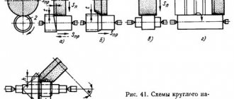
3A423 cylindrical grinding machine is designed for regrinding the main and connecting rod journals of crankshafts with a length of up to 1600 mm and a weight of up to 130 kg, as well as conical shanks with a slope of up to 3° of crankshafts using the plunge-in grinding method with manual feeding of the grinding wheel.
3A423 machines can be used at car repair plants and other enterprises engaged in the restoration of crankshafts, repairing internal combustion engines of cars and trucks, tractors, mini tractors, walk-behind tractors and other equipment.
The presence of an upper rotary table on the 3A423 makes it possible to grind the tapered shanks of crankshafts with a small taper, as well as other tapered parts.
Balancing the crankshaft on the 3A423 when grinding the connecting rod journals is carried out using movable weights on chucks.
The developer is Lubensky Machine Tool Manufacturing.
Grinding crankshaft journals on a cylindrical grinder
The crankshaft serves to receive forces from the connecting rods associated with the engine piston and transmit these forces to the transmission of a car or tractor. Thus, the crankshaft converts the alternating reciprocating motion of the pistons into rotational motion. In the crankshaft, the main and connecting rod journals are ground, and the following tolerances must be maintained:
- diameter tolerance 6 - 10 microns
- tolerance for non-roundness and non-cylindricity 3 µm
- roughness Ra = 0.63 µm
- non-parallelism of the axes of the main and connecting rod journals 6-8 microns
Grinding crankshaft journals presents significant difficulties due to its complex configuration, unbalance, limitation of the journal by two sides, a larger ratio of the shaft length to the diameter of the journals and, therefore, its reduced rigidity. The main journals are ground on high-power cylindrical grinding machines.
The crankshaft must be pre-balanced together with the headstock and tailstock.
Balancing the crankshaft when grinding the connecting rod journals is carried out with movable weights placed behind the headstocks of the product in the non-working area. Balancing of heavy crankshafts is carried out by shifting additional movable weights on the chuck faceplate.
To achieve cylindricity of the grinded neck, the upper table allows a slight rotation.
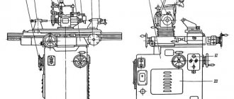
3A423 Location of cylindrical grinding machine controls
Location of controls for cylindrical grinding machine 3a423
List of grinding machine controls
- Headstock faceplate fixing handle
- Two-speed engine speed shift knob
- Flywheel for manual table movement
- Handle for hydraulic table movement
- Coolant valve
- Indicator of axial movement of the grinding headstock
- Grinding wheel cross feed flywheel
- Flywheel for axial movement of the grinding headstock
- Handle for quick withdrawal and supply of the grinding head
- Tailstock faceplate fixing handle
- Tailstock quill retraction handle
- Center pressure flywheel
- Upper table rotation screw
- Table rotation indicator device
- Mechanism for moving the tailstock on the table
- Table reverse stop
- Button “Product “Start-Stop”
- Light switch
- Switch "Automatic operation"
- Button “Product rotate”
- Handle for blocking table movement during plunge-cut grinding
- Feed control handle for plunge-cut grinding
- General Stop button
- Handle for adjusting the speed of hydraulic table movement
- Button “Switch on grinding wheel and hydraulic pump”
3A423 Kinematic diagram of a cylindrical grinding machine
Kinematic diagram of the 3a423 cylindrical grinding machine
By means of a number of kinematic chains and a hydraulic drive, the following movements are carried out in the 3A423 machine:
- Grinding wheel spindle rotation
- Product rotation
- Manual cross feed of the grinding headstock (grinding wheel)
- Quick (hydaulic) approach and retraction of the grinding headstock
- Hydraulic feed of the grinding headstock for infeed
- Manual longitudinal movement of the table
- Longitudinal movement of the table by hydraulic drive
- Axial manual movement of the grinding head spindle
- Axial manual movement of the tailstock quill
- Vertical movement of chucks
- Automatic editing of the circle periphery
DATA SHEET (manual, documentation) FOR GRINDING MACHINES
MACHINE PASSPORT:
A passport is the main technical document containing data characterizing the machine, recommendations for installing it and caring for it. The passport indicates the main dimensions of the machine , spindle and table speeds, feed rates, the maximum permissible torque on the spindle and power . It contains information about the main accessories and devices for the machine, about the drive, hydraulic mechanisms, machine control circuit , about eliminating defects during operation, provides electrical and hydraulic circuits, kinematic diagram , specification of bearings, gears, electric motors, spools, valves and others devices. The passport is used by the workshop technologist as a document for assigning processing modes, selecting devices, and planning the placement of the machine in the workshop. The passport is also necessary for mechanics and power engineers as a guide to the operation and repair of the machine; It contains data on repairs and modernization carried out. During the operation of the machine, various malfunctions may arise, which can be eliminated by the worker himself or reported to a repairman. Instructions on methods for correcting defects are given in the passport.
MACHINE DATA SHEET:
a “Machine Operation Manual” by the manufacturer . “ Manual ” contains: a brief description of the purpose and scope of the machine; instructions for moving (transporting), unpacking and installing the machine (with a drawing of the foundation); description of the design of the main assembly units (assemblies) of the machine; instructions for starting and servicing the machine; electrical equipment passport and electrical diagram of the machine. A separate component of the manual is the machine PASSPORT , drawn up on special standard forms. The passport contains: basic machine data (characteristics); specification of assembly units (assemblies) of the machine; table of the main parameters of gears, worms, screws and nuts; kinematic diagram of the machine ; a table of the mechanics of the main movement (the position of the handles and the corresponding spindle speeds, the highest permissible torques, powers, efficiency, indications of weak links); table of the feed mechanism (position of the handles and corresponding feed values), layout and specification of bearings. The “Manual” contains drawings of the most frequently replaced machine parts. The machine operator begins familiarizing himself with the new machine by studying the machine’s passport and the “ Machine Operation Manual” . These documents are also used when repairing and adjusting the machine, changing lubricants, upgrading the machine or installing special devices on it.
General instructions for operating the 3A423 cylindrical grinding machine
Before moving the headstock and tailstock, you need to wipe down the top table. If grinding will be carried out in the centers, then, when inserting them, carefully wipe the conical sockets of the spindles of the headstocks, making sure that there are no nicks on the centers. Wipe and lubricate the working parts of the centers. Make sure there is no dirt or dust in the center holes of the product and wipe them. Failure to comply with these rules can lead to a sharp decrease in the quality of grinding.
Wheel balancing is of great importance, so it must be performed according to the rules set out in the section “Balancing the grinding wheel”. Working with an unbalanced wheel is not permitted.
At the end of the shift, it is recommended to spin the grinding wheel at full operating speed for 1-2 minutes, turning off the cooling, so that the wheel gets rid of the liquid that accumulates in its lower part and disrupts the balance.
When sanding, steady rests are used. Only under this condition can the product be ground with the required accuracy.
You should not strive to process all products with the same circle. The characteristics of the wheel must be selected in accordance with the material of the product and the requirements for cleanliness, accuracy and grinding performance.
Too much cross feed does not lead to faster work, but to excessive heating of the product and increased wheel wear.
If the grinding quality is poor, you should not always conclude that the adjustment of the spindle bearings of the grinding headstock is incorrect. The design of the supports allows for play of the non-rotating spindle in the radial direction.
It is necessary to adjust the spindle bearings of the grinding headstock only in cases of extreme necessity (see sections “Grinding headstock” and “Grinding defects and measures to eliminate them”).
Grinding wheel attachment
Place a cardboard gasket, a grinding wheel, a second gasket and a pressure flange in sequence on the centering lip of the flange. Insert and tighten the fastening screws so as to lightly clamp the grinding wheel; then tighten diametrically opposed screws evenly to ensure secure and even clamping of the circle. The diameter of the cardboard spacers should be slightly larger than the outer diameter of the flange. The grinding wheel must fit freely onto the centering lip of the flange. Do not force the grinding wheel onto the flange, as this may cause cracks in the wheel.
Balancing the grinding wheel
Place the balanced grinding wheel on the spindle of the grinding headstock and rough the diamond. Remove the grinding wheel together with the flange and re-balance it carefully.
Balancing the grinding wheel is carried out by changing the position of the balancing weights in the annular recess of the grinding wheel flange.
Wheel balancing devices are not supplied with the machine.
Balancing weights are secured in the desired position using screws with conical shanks and balls that press the weights to the surface of the flange recess.
After finishing the balancing, you need to reinstall the grinding wheel on the spindle and grind it clean.
It should be borne in mind that as the wheel wears, its balancing may be disrupted due to the uneven density of the abrasive material.
Improper wheel balancing can lead to vibrations, heating of spindle bearings, etc.
Troubleshooting problems of this nature involves re-balancing the grinding wheel.
Cylindrical grinding machines for metal - explained in general terms
Cylindrical grinding machines belong to the class of metalworking equipment. With their help, they perform precise grinding of metal workpieces along the outer surface. Structurally, machines of this type differ significantly from similar equipment.
Popular categories
By the way, on the ProStanki portal the selection of offers for a cylindrical grinding machine for metal is almost the same as on Avito and TIU
Purpose and types of cylindrical grinding machines
Cylindrical grinding machines belong to the class of metalworking equipment. With their help, they perform precise grinding of metal workpieces along the outer surface. Structurally, machines of this type differ significantly from similar equipment.
Design features of the equipment
The operating principle of cylindrical grinding machines is based on pressing the workpiece using a guide wheel or mounting in cents. In this case, processing is performed by touching the working rotating abrasive to the surface of the part. This ensures uniform material removal with the formation of an optimal roughness index.
The classic layout of the machine is a combination of turning and grinding. To fix the workpiece, a special block is provided in the design. This may be a system of chucks that hold the part in a horizontal position. An alternative is to use an additional wheel that presses the workpiece against the abrasive.
The cylindrical grinding machine has the following advantages of use:
- ability to process parts with different dimensions. It is important to take into account their mass;
- fine tuning of parameters. To ensure high quality grinding, it is recommended to purchase models with automatic feed;
- selection of a machine model for specific production tasks. This will ensure maximum productivity and reduce product costs.
However, to choose the optimal machine model, you need to familiarize yourself in detail with their varieties and performance qualities. It all depends on the configuration of the parts being processed, as well as the requirements for grinding quality.
An important point is the configuration of the abrasive disc - its grain size and working surface area. These characteristics directly affect the grinding quality of the steel workpiece.
Types of cylindrical grinding machines
An example of the layout of the ZM151 machine
In practice, cylindrical grinding machines process workpieces of round or oval cross-section. Grinding complex parts is impossible with this equipment due to the specifics of its design. This must be taken into account when choosing a machine model.
The most common models of cylindrical grinding machines are equipment in which the parts are mounted on centers. The workpiece is fixed between the front and tailstock. To improve the quality of grinding, the body rotates. When it comes into contact with the abrasive disc, excess material is removed in the form of metal dust and shavings.
In addition to this technique, so-called centerless cylindrical grinding machines have recently gained popularity. In them, the workpiece is placed on a working carriage and is held on one side by an auxiliary wheel, and on the other is subjected to grinding with the main abrasive. In this way, high-quality fine machining of thin-walled cylinders or cones can be performed. The degree of pressing is adjusted using an automatic system.
Additionally, it is necessary to take into account the following features that the cylindrical grinding machine has:
- presence of a rotary table. With its help, you can shift the workpiece relative to the abrasive disk in the horizontal and vertical plane;
- feed mechanism device. This can be an automated complex or its mechanical analogue. In the latter case, machines of this type are used for rough grinding;
- Possibility of fixing the workpiece in centers or chucks. This parameter applies to center type equipment only.
Electrical equipment of machine 3A423
General information
The machine is equipped with four three-phase squirrel-cage asynchronous electric motors (Fig. 20):
- grinding wheel drive electric motor type AO2-52-6 with a power of 7.5 kW, 970 rpm;
- product drive electric motor type AO2-31-6/4 with a power of 0.75/1.1 kW, 950/1440 rpm;
- hydraulic pump type AO2-31-6 electric motor with a power of 1.5 kW, 950 rpm;
- electric pump motor for coolant type PA-22 with a power of 0.12 kW, 2800 rpm.
The machine is produced with electrical equipment for a voltage of 380 V with a frequency of 50 Hz in the power circuit.
By special order, the machine can be made with electrical equipment for voltages of 220, 400, 415, 440 V with a frequency of 50 Hz in the power circuit.
The control circuit is powered by 127 V through a step-down transformer.
The machine is equipped with local lighting with a voltage of 36 V.
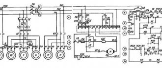
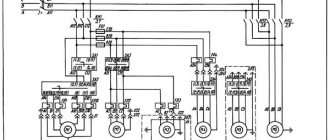
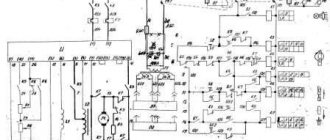
Operation of the electrical circuit of the 3A423 machine
To start the machine, you need to close the overhead line switch (Fig. 21, 22) and then alternately press the KPSh and KPI buttons.
When the KPS button is pressed, the electric motors of the grinding wheel, hydraulic pump and cooling pump are started, and when the KPI button is pressed, the electric motor of the product is turned on.
A jog mode is provided (rotation of the product); to do this, press the KTI button.
All electric motors are switched off using the KS button.
The machine has two operation control modes:
- Semi-automatic mode
- Manual mode
In semi-automatic mode, the contacts of the OBD switch are closed. Quick supply of the grinding head is carried out from handle 9 (see Fig. 4).
Upon completion of the plunge, the mechanism stop acts on the KO microswitch, the closing contact of which will close, the EP electromagnet will receive power through the RO relay and switch the hydraulic system spool; the grinding wheel will be removed from the product.
During manual operation, the contacts of the VA switch are open and the grinding headstock does not retract. In this case, quick retraction of the grinding head is carried out by handle 9.
Protection
Protection of the electrical equipment of the machine from short circuits is carried out by automatic switches VL, AG, AI and fuses PU, PO, and protection of electric motors from overloads by thermal relays RTSh, RTG, RTN. Thermal relays have manual reset.
Crankshaft regrinding machine 3A423
Crankshaft regrinding machine 3A423
Message #1 Texman » 05 Dec 2022, 22:31
General reference topic on this machine and on the subtle points of working on it. As problems arise and they are resolved, I will write posts in a question-and-answer format.
There is no need to flood, you need to post useful information.
===================================================== ============ Main drive belts: length 1600, profile B Product drive belts: length 900, profile A Main engine bearings: 76-180607С9Ш Product drive bearings: 76-180609С9Ш ====== ===================================================== ====== Grinding wheel drive motor: AO2-52-6, 7.5 kW, 970 rpm Product drive motor: two-speed AO2-32-6/4, 0.75/1.1 kW, 950/1440 rpm Hydraulic pump drive motor: AO2 -32-6 (not sure), 1.5 kW, 950 rpm Standard pump PA-22 ============================= ================================ Hydraulic pump: G12-23 ========================== ==================================================== Broken The carbolite steering wheel can be easily replaced with a steering wheel from a ZIL-130: the fit is bored to the diameter of the bushing from the original steering wheel, then tacked on by welding. ===================================================== ============
Commercial break:
A team of people from the Lubensky plant (Ukraine), which produced these machines, travels around the CIS. One good person from her helped me figure out my device. Contact us, contacts are listed in the video.
Crankshaft regrinding machine 3A423
Post #2 Texman » 17 Aug 2022, 16:44
Scraps of thoughts that may be useful to someone.
The upper table, on which the headstocks move, is probably the most frequently damaged part in the machine. If the grinder does not wipe its guides before each movement of the headstocks, then the abrasive gets under them - and that’s it, accelerated wear begins. If the grinder is not a drunken redneck, then he always keeps the table clean.
There is also a problem area - the drive headstock faceplate. Through it, the emulsion gets inside, the consequences are very sad - the chain and bearing deteriorate. In the faceplate itself there is an annular recess, seemingly for a felt seal, but not everyone has a seal. By the way, at the bottom-back of the headstock, under the place where the electrical cable comes out, there is a drain plug - it would be a good idea to drain the chacha accumulated in the headstock through it from time to time.
—– What to do if a cut appears on the necks of the product? You need to adjust the chain with a bolt for the internal hexagon S=12, it is located on the drive headstock from below above the guide closest to the working one, and is locked with a round nut. If you can’t adjust it, it means the chain is covered, and maybe the sprocket is too. You need to buy a new one, you can buy it from those guys whose advertisement is above. I have no idea where to get these spare parts in Russia.
—– Why did ellipse and taper appear on the necks of the product after grinding? The reason, as a repairman from the Lubensky plant told me, is the misalignment of the headstocks. This misalignment occurs due to the previous point - abrasive wear of the upper table guides.
—– What to do if the cones in the spindle of the drive headstock and in the driven quill are damaged, and there is no way to repair them? You can make a faceplate for the product’s drive head (drive) for a four-jaw chuck and work with it. And just hammer the quills onto the raised surface of the cone. (for reference, you can’t just grind the 60-degree cone of the thrust center on this machine, like you can on a regular cylindrical or thread grinder)
—– Why is there a yellow-white emulsion in the tank instead of oil? Because coolant got into the oil. Where did it come from? Most likely through a long shield screwed along the top table. In theory, it should fit tightly to the table, but in fact this is not always the case. It is best to screw the rubber-lined shield through a rigid bar to prevent the tin from bubbling. There is also the possibility of water getting in from the three drain holes going through the top table. It is necessary to either plug them from the operator's side, or insert corrosion-resistant tubes into them of such length that it overlaps the prismatic guide with a margin.
3A423 Hydraulic diagram of a cylindrical grinding machine
Hydraulic diagram of cylindrical grinding machine 3a423
Hydraulic diagram of cylindrical grinding machine 3a423
- 1. Vane pump G12-23 1
- 7. Locking cylinder of the table manual movement mechanism - 1: In the table manual movement mechanism
- 12. Headstock play cylinder -1: In the grinding headstock plate
- 20. Cylinder for quick approach and removal of the grinding headstock - 1: In the grinding headstock plate
- 24. Quick feed cylinder piston - 1:
- 26. Check valve - 2: In the quick feed cylinder
- 29. Table mortise feed cylinder - 1: On the quick feed cylinder
- 30. Control handle for quick approach of the grinding head - 1: On the front panel of the bed
- 31. Quick feed control spool - 1: On the quick feed cylinder
- 32. Infeed speed throttle - 1: On the front panel of the bed
- 33. Check valve - 1: In the infeed throttle
- 34. Table locking mechanism - 1: On the hydraulic panel bracket
- 35. Switch for the type of work (“Grinding” - “Editing”) - 1: On the front panel of the bed
- 36. Table start handle - 1: On the front panel of the bed
- 37. Check valve - 2: In the hydraulic panel
- 38. Throttle for smooth acceleration of the table - 2: In the hydraulic panel
- 39. Throttle for regulating table delay time - 2:
- 40. Hydraulically controlled reverse spool - 1:
- 41. Mechanically controlled reverse spool - 1:
- 42. Reverse stops - 2: On the lower table
- 43. Table start valve - 1:
- 44. Reverse lever - 1: On the hydraulic panel bracket
- 45. Pressure fluctuation damper in the hydraulic system - 1: In the pressure spool
- 46. Table speed throttle - 1:
- 48. Adjusting screw 1: In the pressure spool
- 49. Pressure spool 1:
- 50. Plate filter 1:
- 51. Pressure gauge MT-4 GOST 8625-59 for a pressure of 25 kgf/cm2 1:
- 52. Receiving mesh filter C41-12 1:
Technical characteristics of the machine 3A423
| Parameter name | 3V423 | 3A423 |
| Main settings | ||
| Accuracy class according to GOST 8-71 | P | P |
| Largest diameter of the installed product, mm | 580 | 580 |
| Maximum length of the installed product in centers, mm | 1600 | 1600 |
| Maximum length of the installed product in cartridges, mm | 1450 | 1500 |
| Grinding diameter without steady rest, mm | 30..150 | 30..150 |
| The largest grinding diameter in the steady rest, mm | 30..110 | 30..100 |
| Maximum grinding length, mm | 1600 | 1600 |
| Distance from the axis of the headstock spindle to the table mirror - height of centers, mm | 300 | 300 |
| Maximum crank radius, mm | 105 | 110 |
| Maximum mass of the processed product, kg | 150 | 130 |
| Machine bed and tables | ||
| Maximum longitudinal movement of the table by hand/by hydraulics, mm | 1600/ 1600 | 1600/ 1600 |
| Table movement speed from the hydraulic system, m/min | 0,2..4,0 | 0,2..7,0 |
| Manual slow/fast movement of the table per revolution of the flywheel, mm | 2/ 15,2 | 5,3/ 14,2 |
| Minimum table travel between stops, mm | ||
| Maximum angle of rotation of the upper table clockwise, degrees | 2 | 2 |
| Maximum angle of rotation of the upper table counterclockwise, degrees | 3 | 3 |
| Maximum taper of the top table clockwise, mm | 0,075 | 0,075 |
| Maximum taper of the top table counterclockwise, mm | 0,1 | 0,1 |
| Upper table rotation scale division price, min | 15 | |
| Scale division of the upper table (taper), mm | 0,005 | |
| Grinding head | ||
| Grinding wheel diameter - smallest/largest, mm | 750/ 900 | 600/ 900 |
| Grinding wheel diameter - landing, mm | 305 | 305 |
| Maximum height of the installed circle, mm | 63 | 40 |
| Number of spindle speeds of the grinding head | 2 | |
| Grinding head spindle rotation speed, rpm | 740 | 730..830 |
| Grinding spindle end, mm | 1:5 | 1:5 |
| Cross feed mechanism of the grinding headstock | ||
| Maximum movement of the grinding head along the screw, mm | 175 | 210 |
| The size of the rapid hydraulic supply of the grinding head, mm | 100 | 50 |
| Time for rapid hydraulic supply of the grinding head, s | ||
| Jog feed - periodic feed with table reversal (per tooth of the ratchet wheel), mm | 0,0025 | 0,0025 |
| Transverse feed dial division price, mm | 0,005 | 0,005 |
| Fine cross feed dial division price, mm | 0,0025 | 0,0025 |
| The amount of transverse movement of the grinding head per revolution of the flywheel (limbe), mm | 0,5 | 0,5 |
| Speed of fast installation movement of the grinding head, mm/min | ||
| Headstock | ||
| Product rotation frequency (at a current frequency of 50 Hz), rpm | 30, 60, 90, 180 | 31, 62, 108, 216 |
| Number of product rotation speeds | 4 | 4 |
| Headstock spindle taper | Morse 5 | Morse 5 |
| Tailstock | ||
| The amount of retraction of the tailstock quill by hand using a lever/screw, mm | 35/ 55 | 35 |
| Tailstock quill spindle cone | Morse 4 | Morse 4 |
| Drive and electrical equipment of the machine | ||
| Number of electric motors on the machine | 7 | 4 |
| Grinding head spindle electric motor, kW | 11,0 | 7,5 |
| Electric motor of the cooling system pump, kW | 0,25 | 0,125 |
| Magnetic separator electric motor, kW | 0,09 | — |
| Electric motor of the main hydraulic system pump, kW | 2,2 | 1,7 |
| Electric motor of the spindle lubrication system pump, kW | 0,09 | — |
| Electric motor of the table guide lubrication system pump, kW | 0,09 | — |
| Product drive electric motor, kW | 1,75 | 0,7/ 1,2 |
| Overall dimensions and weight of the machine | ||
| Overall dimensions of the machine (length x width x height), mm | 5500 x 2550 x 1670 | 4600 x 2100 x 1580 |
| Weight of the machine with electrical equipment and cooling, kg | 8180 | 5750 |
- Special cylindrical grinding machine for regrinding automotive crankshafts 3A423. Manual and passport, 1966
- Alperovich T.A., Konstantinov K.N., Shapiro A.Ya. Design of grinding machines, 1989
- Alperovich T.A., Konstantinov K.N., Shapiro A.Ya. Setup and operation of grinding machines, 1989
- Dibner L.G., Tsofin E.E. Sharpening machines and semi-automatic machines, 1978
- Genis B.M., Doctor L.Sh., Tergan V.S. Grinding on cylindrical grinding machines, 1965
- Kashchuk V.A., Vereshchagin A.B. Grinder's Handbook, 1988
- Kulikov S.I. Honing, 1973
- Lisova A.I. Design, adjustment and operation of metal-cutting machines, 1971
- Loskutov V.V. Metal grinding, 1985
- Loskutov V.V. Grinding machines, 1988
- Lurie G.B. Grinding machines and their adjustment, 1972
- Lurie G.B. Design of grinding machines, 1983
- Menitsky I.D. Universal sharpening machines, 1968
- Mutsyanko V.I. Bratchikov A.Ya. Centerless grinding, 1986
- Naerman M.S., Naerman Ya.M. Guide for training grinders. Textbook for vocational schools, 1989
- Popov S.A. Grinding work, 1987
- Tergan V.S. Grinding on cylindrical grinding machines, 1972
- Shamov B.P. Types and designs of main components of grinding machines, 1965
Bibliography:
Related Links. Additional Information
- Classification and main characteristics of the grinding group
- Repair, restoration and modernization of grinding machines: the American approach
- Cylindrical grinding. Processing on cylindrical grinding machines. Grinding Methods
- Setting up a cylindrical grinding machine when installing parts in centers
- CNC grinding machines
- Marking of grinding wheels
- Testing and checking metal-cutting machines for accuracy
- Grinding machines. Market of grinding machines in Russia
- Directory of grinding machine manufacturers
- Directory of factories producing metal-cutting machines
- Directory of surface grinding machines
- Articles on the topic
Home About the company News Articles Price list Contacts Reference information Interesting video KPO woodworking machines Manufacturers
Cylindrical grinder for crankshafts 3A423
The special cylindrical grinding machine model 3A423 is designed for regrinding connecting rods and main journals of crankshafts of automobile and tractor engines in auto repair plants and other repair services. The machine can grind cylindrical surfaces and conical surfaces with a slight inclination angle. The machine control is electromechanical, hydraulic and manual. The machine can perform grinding with automatic plunge-in.
| Specifications | |
| Largest dimensions of the installed product, mm, diameter/length | 580/1600 |
| Grinding diameter, mm: | |
| -least | 30 |
| -with rests/without rests | 100/150 |
| Maximum grinding length, mm, in centers / in chucks | 1600/1500 |
| Maximum permissible radius of the product crank, mm | 110 |
| Maximum permissible weight of the product, kg | 130 |
| Maximum longitudinal movement of the table, mm, manual / hydraulic | 1600/1600 |
| Speed of hydraulic movement of the table, mm/min, max./max. | 7000/200 |
| Hydraulic pump motor: | |
| -power, kWt | 1,5 |
| - number of revolutions per minute | 950 |
| Grinding wheel diameter, mm, largest/smallest | 900/600 |
| Maximum height of the grinding wheel, mm | 40 |
| Wheelhead spindle revolutions per minute | 830-730 |
| Rotating the grinding head | No |
| Machine dimensions (length×width×height), mm | 4600×2100×1580 |
| Machine weight, kg | 5750 |