Information about the manufacturer of the semi-automatic cylindrical grinding machine 3B161
The manufacturer of the semi-automatic cylindrical grinding machine 3B161 is the Kharkov Machine Tool Plant , currently JSC Kharkov Machine Tool Plant.
The plant was founded on January 29, 1936 and specializes in the production of universal and special cylindrical grinding machines
Machine tools produced by the Kharkov Machine Tool Plant
Differences between machines models 3A151, 3A161, 3B151, 3B161
3A151 and 3A161 machines have a hydraulic plunge-in mechanism with a semi-automatic operating cycle and are designed for both plunge-cut and longitudinal grinding, and are designed primarily for operation in serial and mass production conditions, but can also be used in individual production.
Machines models 3A151 and 3A161 are recommended for plunge-cut and longitudinal grinding of small, medium and large batches of identical parts with a diameter of 10 to 40 mm. To do this, they must be configured for longitudinal grinding with automatic transverse feed or for plunge grinding to the stop with a semi-automatic operating cycle. If there is an active control device (it is supplied with machines on special order and at an additional cost), the grinding cycle is controlled automatically depending on the actual size of the product.
The following types of processing can be performed on machines models 3A151 and 3A161:
- longitudinal and plunge grinding with manual control;
- longitudinal grinding with automatic transverse feed, carried out when the table is reversed;
- Plunge grinding to the stop in a semi-automatic operating cycle.
On the machines of these models, it is possible to install active control devices, which are supplied with them on special order and for an additional fee.
Machines models 3B151 and 3B161 do not have a hydraulic plunge mechanism. They are designed mainly for longitudinal grinding and are equipped with an automatic transverse feed mechanism, which occurs when the table is reversed. They can also be used for plunge-cut and longitudinal grinding with manual transverse feed.
Machines of models 3B151 and 3B161 are designed to work in conditions of serial and single production.
Machines models 3A161 and 3B161 have a larger working space (Ø 280 x 1000 mm) compared to models 3A151 and 3B151 (Ø 200 x 700 mm).
Basic information
A cylindrical grinding machine is a device for automatically grinding metal products. The installation looks like a large table on which additional grinding equipment is installed. The operating principle of cylindrical grinding machines is simple. Using headstocks or a carriage, the metal part to be processed is installed in the working area. After this, the grinding wheel is started and rotates around its axis. The circle approaches the workpiece, which leads to stripping of the metal workpiece.
Using a cylindrical grinding machine, you can process cylindrical, conical and end workpieces, as well as large holes. By design, there are centered and centerless models. For center models, the workpiece is secured using special grooves. In centerless models, the workpiece is fixed in the working area of the machine using a clamping carriage. A cylindrical grinding machine performs the following tasks: abrasive rubbing of the surface of the workpiece, removing an excess layer of metal, eliminating irregularities on the metal surface.
Elements of cylindrical grinding systems
- Desktop. Acts as a base on which all the main elements are attached. The workbench may have small wheels that are used to transport the unit. The work table is made of durable metal alloys, as are other elements of the grinding system.
- Headstock grooves (center models). Used for fastening parts on the desktop. The grooves can rotate around their axis, which allows you to process the workpiece over its entire area + improves the quality of grinding. Some grooves can also move in the longitudinal direction, which allows you to change the position of the part on the work table directly during processing. The head slots can be movable - this allows you to change the angle of the workpiece on the work table. This makes it possible to grind conical workpieces.
- Carriage (centerless models). The carriage is also used for fastening parts on the work table. The main difference from the headstock grooves is that the carriage does not have its own axis of rotation (it can only be moved in the horizontal direction). To process the workpiece from different sides, the workpiece itself is rotated on the carriage.
- Abrasive disc wheel. Located in a perpendicular direction relative to the location of the workpiece on the work table. During operation, it acts as an abrasive with which processing is performed. Abrasive discs come in different shapes. Simple machines have a fixed disk arrangement. The universal cylindrical grinding machine has a movable disc wheel, which makes the installation more versatile.
- Drive unit. Used to move the abrasive wheel while the system is operating. The drive can be mechanical, hydraulic and electric. Large systems are usually equipped with an electric drive, which simplifies the procedure for moving the disk during operation. Small machines have a mechanical or hydraulic drive, which reduces electricity consumption.
- Electric motor. Acts as an energy source that powers all the main elements of the installation (rotating slots-headstocks, abrasive disc-wheel, etc.). If the machine is equipped with an electric drive, then the engine also powers this element. Electric motors usually have a power ranging from 5 to 15 kilowatts, although more powerful units are also available. Modern electric motors usually have additional protective elements to avoid system overheating.
- Cooling system. During processing, serious heating of the workpiece occurs due to friction. To avoid overheating of the workpiece, many modern machines are equipped with a cooling system. It looks like small taps that are installed in the core. The taps are connected to the refrigerant (the refrigerant is usually water). During processing of the part, the valves are activated, which leads to the spraying of coolant in the core.
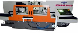
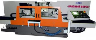
General view of the 3B161 cylindrical grinding machine
Photo of grinding machine 3B161
Photo of grinding machine 3B161
Photo of grinding machine 3B161
Photo of grinding machine 3B161
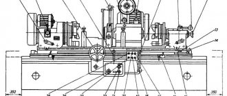
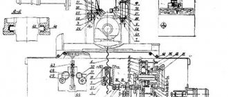
Location of components of the grinding machine 3B161
Location of the main components of the grinding machine 3B161
List and designation of the main components of the 3B161 grinding machine
- 1. machine bed
- 2. grinding head
- 3. hydraulic control
- 4. mechanism for manual movement of the table
- 5. cross feed mechanism
- 6. headstock
- 7. tailstock
- 8. oil line*
- 83. grinding wheel housing
- 85. cooling
- 87. lunette
- 89. device for dressing a grinding wheel
- 91. fence
- 92. mechanism for quick supply of the grinding head (only on machines models 3B151 and 3B161)*
- 92. mechanism for quick approach and insertion (only on machines models 3A150 and 3A161)*
- 95. electrical equipment, control panel
- SHU-270. grinding wheel flange*
- SHU-297. mechanism for balancing the grinding wheel
- SHU-965. correct device*
* Groups and nodes marked with an asterisk are not shown in the figure.
Location of controls for grinding machine 3B161
Location of controls for grinding machine 3B161
List of controls for the grinding machine 3B161
- flywheel for manual table movement
- table handle
- table reverse lever
- table reverse delay control throttle on the left
- periodic feed switching handle (feed when reversing for each table move, feed when reversing the table on the right, feeding when reversing the table on the left, feed is turned off)
- throttle for regulating the speed of table movement when dressing the grinding wheel
- Tailstock quill hydraulic release pedal
- handle for switching table speed from grinding to dressing
- throttle for regulating the speed of table movement when grinding
- Throttle for regulating table reverse delay on the right
- handle for quick approach of the grinding head and start of hydraulic movement of the table
- top table rotation screw
- tailstock quill retraction handle
- tailstock quill clamp handle
- lever
- handle for adjusting periodic feed from ratchet mechanism
- manual cross feed stop
- manual cross feed flywheel
- handwheel for setting the manual cross feed dial
- cooling valve handle
- product rotation start button
- product rotation stop button
- product rotation speed control handle
- "General stop" button
- Cooling pump switch
- light switch
- product rotation start switch (manual - automatic)
- button to start the rotation of the hydraulic pump and lubrication pumps for the guides and spindle bearings of the grinding headstock
- grinding head spindle rotation start button
- product rotation start button
- product rotation stop button
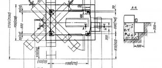
Placement of electrical equipment on the 3B161 machine
Placement of electrical equipment on the 3B161 machine
- product rotation speed controller
- buttons to turn on and off the rotation motor of the product
- machine control panel
- hole for connecting the machine to the network
- ground screw
- limit switch for turning on the rotation of the product rotation electric motor
Kinematic diagram of the 3B161 cylindrical grinding machine
Kinematic diagram of the 3B161 cylindrical grinding machine
Through a series of kinematic chains and a hydraulic system, the following movements are carried out in the machine:
- Rotation of the spindle of the grinding head
- Product rotation
- Manual and automatic cross feed (machines models 3A150 and ZA161 have two types of automatic cross feed - continuous plunge feed and periodic feed, which occurs when the table is reversed; machines models 3B151 and 3B161 do not have automatic plunge feed).
- Manual and hydraulic table movement
- Fast hydraulic supply and removal of the grinding headstock
- Hydraulic outlet of the tailstock quill. The kinematic chains of the main movement, rotation of the product, manual transverse feed and manual movement of the table are clear from the attached diagrams (see Fig. 21 and 22) and therefore their description is not given.
Application area
Cylindrical grinding machines are used for external processing of cylindrical and conical parts made of ferrous and non-ferrous metals using the method of longitudinal, plunge and depth grinding in conditions of single, serial and mass production in the field of metallurgy and mechanical engineering at production sites in the workshops of enterprises. Also, the mentioned equipment can often be found in laboratories and research departments of factories and factories. Compact cylindrical grinding machines are actively used in repair shops, vehicle service stations, and garages. In addition, the units are used in workshops of vocational educational institutions that train machine tool specialists.
Features of cylindrical grinding machines
The equipment design includes the following elements:
- bed;
- upper and lower tables;
- device for internal grinding;
- quill;
- fastenings for grinding wheels;
- headstock;
- electrical cabinet;
- mechanism for straightening the abrasive wheel;
- Remote Control.
We offer to buy a cylindrical grinding machine, which makes it possible to process any metal surface with high precision. It is noteworthy that the work tables of these units can be equipped with additional stiffening ribs to increase strength and make it possible to work with large parts that exhibit significant mass. Hydraulic workpiece feeding systems ensure cyclic processing of parts with minimal time.
In our company's catalog you can buy a cylindrical grinding machine with sliding guides, which are covered with special covers to prevent contamination. Tables move along them, driven by a manual mechanism or a hydraulic system. The presence of a folding indicator device on the front of the high-strength frame allows you to control table movements with high accuracy. Segmental self-aligning bearings on which the spindle of the grinding headstock is mounted provide rigidity of support and increased rotational accuracy.
, which supplies customers from Russia and neighboring countries with equipment for processing metal parts, gives customers the opportunity to buy a cylindrical grinding machine with an electric locking of the grinding head motor, which protects the equipment from overloads. It is also noteworthy that the inclined working surface of the unit helps to move the tailstock and headstock without losing alignment. Grinding wheels of various grain sizes and hardness are used as tools for abrasive processing of parts. To straighten them, special devices with carbide discs are used.
Advantages of cylindrical grinding machines
We advise visitors to buy a cylindrical grinding machine that demonstrates advantages such as:
- safety in use, subject to all rules for working with equipment;
- automatic lubrication system for spindle heads, reducing wear and increasing the service life of spindles;
- a system that makes it possible to regulate the speed of longitudinal transmission without jerking;
- accelerated approach and retraction of the grinding wheel to save time and increase productivity;
- high reliability in use due to the impeccable quality of components from which industrial cylindrical grinding machines are assembled;
- the presence of an effective cooling system that allows reducing the temperature of the grinding wheel during rotation and extending its service life;
- hydraulic or manual (mechanical) high-precision movement of work tables and spindle heads;
- stability of the shape of the working area during load fluctuations;
- devices that ensure quick removal of flanges and, if necessary, replacement;
- the presence of splash guards that prevent liquid contaminated with metal particles from entering the operator’s clothing;
- the possibility of installing magnetic separators or paper filters for the grinding wheel cooling system;
- reliable and durable electric motors that consume moderate electricity;
- stable processing quality;
- maintainability and the ability to replace components.
Hydraulic drive of machines 3B161
The hydraulic system of the machine is driven by a pumping unit consisting of a vane pump, a plate filter drive motor and a discharge valve (Figure 22). The pumping unit is mounted on a separate plate fixed to the back of the machine bed stand.
The operation of the machine’s hydraulic system is controlled using the GSh-001A hydraulic panel mounted in the front part of the frame.
The hydraulic system of the machine performs the following functions:
- longitudinal movement of the table
- table reverse
- moving the table when setting up the machine
- periodic feeding of the grinding headstock
- quick approach and retraction of the grinding headstock
- tailstock quill retraction
- blocking the table manual movement mechanism
- sampling of play in the engagement of the nut and screw of the river feed mechanism
Description of the hydraulic drive of the cylindrical grinding machine model 3A161
Moving the table . The hydraulic movement of the table is carried out by stopping the handle of the crane distributor 6. Oil from the pump 13 is supplied to the distributor through the crane distributors 6 and 4. Depending on the position of the distributor spool 7, the oil enters the right or left cavity of the hydraulic cylinder 21 for moving the table. Oil from the opposite cavity of the hydraulic cylinder 21 is forced to drain through distributors 7, 27, 22, crane distributor 9, throttle 8 and check valve 10. The speed of the table during grinding is controlled by throttle 5. Before editing, it is necessary to turn off the oscillating movement of the grinding spindle with the handle of crane distributor 9, setting it to the “Edit” position. Oil draining from the hydraulic cylinder 21 for moving the table when editing will occur through the throttle 16. When moving the table, oil under pressure also enters the hydraulic cylinder 15 of the blocking mechanism for manual movement of the table and disengages its clutch.
Reverse table . When the distributor 27 is switched by the reverse lever, operated by stops, the oil is directed under the end of the distributor spool 7 and by pressure moves it to the right or left position. The cavities of the hydraulic cylinder 21 for moving the table are alternately under pressure, and the direction of movement of the table automatically changes. Chokes 23 regulate the delay of the table, and chokes 18 control the smooth acceleration of the table during reverse.
The table is moved by the handle of the crane distributor 19 with the grinding head retracted and the hydraulic movement of the table turned off. Oil from the rod cavity of the cylinder 28 for the quick supply of the grinding headstock through the valve distributor 6 flows to the left end of the distributor spool 17 and to the upper end of the distributor spool. 22. The distributor spool 17 will move to the right, connecting the non-working cavity of the table movement cylinder 21 with the drain through the distributor 19. The distributor spool 22 will move down and block the passage of oil from the cylinder 21 to the chokes 8 and 16. To move the table, it is necessary to tilt the distributor handle 19 to the right or left .
Periodic supply of the grinding headstock is switched on by the crane distributor 37; it can be done with each stroke, with the table reversed to the left, or with the table reversed to the right.
Periodic feeding from the rotation mechanism . The handle of the tap distributor 4 is set to the “Periodic supply” position. The handle of the crane distributor 34 is set to the “From the cutting mechanism” position. Oil from the lower cavity of the cylinder 31 of the plunger mechanism passes through the valve distributor 4 and is blocked by the spool of the distributor 35. When the table is reversed and the distributor 27 is switched, chamber a is connected to chamber b, to which oil is supplied. Oil under pressure is supplied to the end of the distributor spool 35 through the channels of the valve distributor 37 and the groove of the distributor spool 38. The distributor spool 35 will move to the lower position. Oil from the cutting cylinder 31 enters the cavity of the dispenser 36; its piston, compressing the spring, moves to the stop, the position of which determines the amount of feed. At the same time, oil from chamber a will flow through check valve 20 to the end of the distributor spool 7 and move the spool to one of its extreme positions; The direction of table movement will change. The distributor spool 38 will move to the opposite extreme position, as a result of which the end cavity of the distributor 35 is connected to the drain through the channels of the valve distributor 37 and the distributor 27. The distributor spool 35 will move upward under the action of the spring, connecting the dispenser cavity 36 with the drain. To compensate for leaks that disrupt the stability of small feeds, a throttle 30 is provided.
Intermittent feed from ratchet mechanism . The handle of the tap distributor 4 is set to the “No supply” position. The handle of the tap distributor 34 is in the “From the periodic feed mechanism” position. At the moment of table reverse, oil from distributor 38 is directed to cylinder 39 of the periodic feed ratchet mechanism. The piston of cylinder 39 will move to the right, the pawl will turn the wheel and with it the horizontal shaft of the cross feed mechanism, producing feed. The feed amount is adjusted with a screw.
The quick supply and removal of the grinding head is activated by the handle of the distributor 5. Oil enters the piston cavity of the cylinder 28 through the distributor 5, the rod cavity of the cylinder is connected to the drain. The quick release is activated by the distributor handle 5 or the distributor electromagnet 3.
Continuous feed of the grinding headstock (plunging) . The handle of the tap distributor 4 is set to the “Continuous supply” position. The headstock feed is turned on by tilting the distributor handle 5; there is a quick supply of the headstock to the product. The plunge is made by turning the cam, which is rotated by the piston-rack of the cylinder 31 of the plunge mechanism, until it comes into contact with a fixed stop. Oil flows to the upper end of the piston-rack of cylinder 31 from the right cavity of the cylinder 28 of the rapid supply of the grinding headstock when the piston of cylinder 28 approaches the extreme left position. From the opposite cavity of the cylinder 31 of the cutting mechanism, oil is forced out to drain through the valve distributor 4, the control distributor 2 and the throttle 40, the setting of which determines the cutting speed. At the end of the plunge, the distributor spool 3 is moved by an electromagnet to the lower position, and the headstock is quickly withdrawn.
Accelerated feed of the grinding headstock after rapid approach is carried out by tilting the handle connected to the throttle 40 to the right.
After the spark appears, the handle is lowered and grinding occurs at a feed speed determined by throttle 40.
The tailstock quill can only be retracted when the grinding head is retracted. The pintle is retracted by a foot pedal connected to the distributor 33.
Plunge grinding when working with an active control device. After the finishing feed, a command is sent to the electromagnet, which moves the spool of the control distributor 2, the oil from the lower cavity of the cylinder 31 of the plunge mechanism is drained through the finishing feed throttle 1. When the specified product size is reached, the device sends a command to the distributor electromagnet 3; The grinding wheel is quickly withdrawn.
Tracking rest . When installing the follower steady rest, the oil supply to the steady rest cylinder 29 must be carried out according to Fig. 29.
Automatic shutdown of the oscillating movement mechanism occurs when the tap distributor 9 is switched to the straightening position. The hydraulic panel channel, communicating with the crane distributor 9, is connected to the cylinder 26 for turning off the mechanism for the oscillating movement of the grinding headstock spindle.
Elimination of the gap in the cross-feed mechanism (cross-feed screw pair) is carried out by cylinder 25.
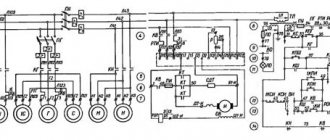
Electrical circuit diagram of the machine 3B161
Electrical diagram of the 3B161 cylindrical grinding machine
The machines are equipped with seven electric drives: grinding wheel, hydraulic pump, cooling pump, grinding head spindle bearing lubrication pump, bed guide lubrication pump, magnetic separator and workpiece.
All electric drives, except for the product drive, have three-phase asynchronous electric motors with a squirrel-cage rotor. The electric drive of the product has a DC electric motor with a parallel field winding, which receives power from a block of magnetic amplifiers and rectifiers.
The speed of the electric motor driving the product can be steplessly adjusted from 250 to 2500 rpm.
The machines are equipped with local lighting from a reduced voltage of 36 V.
A voltage of 127 V is provided for control circuits.
Purpose of the metal machine 3B161
The semi-automatic machine is designed for external grinding of cylindrical and flat conical surfaces in mass production conditions. Grinding is carried out in fixed centers
Technical characteristics of the machine 3B161
We offer to buy new or overhauled analogues of equipment such as 3B161 cylindrical grinding machine at a competitive price. You can select the appropriate model yourself on our website in the CATALOG section, or by consulting the sales department of our company.
The sale of analogues of the machine model 3B161 is made with 100% prepayment if the equipment is in stock and 50% prepayment when the machine is put into production at the manufacturer and payment of the remaining 50% after notification of its readiness for shipment. Another jointly agreed upon payment procedure is possible.
The warranty for products similar to the product - Cylindrical grinding machine 3B161 is:
- new machines - 12 months,
- after major repairs - 6-12 months.
Manufacturers reserve the right to change the standard configuration and place of production of equipment without notice!
We draw your attention to the fact that the prices indicated on our website are not a public offer, and check the cost of the equipment with our sales managers of machine tools and forging equipment!
If you need to buy a 3B161 cylindrical grinding machine, call:
in Moscow in St. Petersburg in Minsk +375 (17) 246-40-09 in Ekaterinburg in Novosibirsk in Chelyabinsk in Tyumen +7 (3452) 514-886
in Nizhny Novgorod in Samara in Perm in Rostov-on-Don in Voronezh in Krasnoyarsk
in Nur-Sultan;
in Abakan, Almetyevsk, Arkhangelsk, Astrakhan, Barnaul, Belgorod, Blagoveshchensk, Bryansk, Vladivostok, Vladimir, Volgograd, Vologda, Ivanovo, Izhevsk, Irkutsk, Yoshkar-Ola, Kazan, Kaluga, Kemerovo, Kirov, Krasnodar, Krasnoyarsk, Kurgan, Kursk , Kyzyl, Lipetsk, Magadan, Magnitogorsk, Maikop, Murmansk, Naberezhnye Chelny, Nizhnekamsk, Veliky Novgorod, Novokuznetsk, Novorossiysk, Novy Urengoy, Norilsk, Omsk, Orel, Orenburg, Penza, Perm, Petrozavodsk, Pskov, Ryazan, Saransk, Saratov, Sevastopol, Simferopol, Smolensk, Syktyvkar, Tambov, Tver, Tomsk, Tula, Ulan-Ude, Ulyanovsk, Ufa, Khabarovsk, Cheboksary, Chita, Elista, Yakutsk, Yaroslavl and other cities
Toll-free number throughout Russia.
In the CIS countries - Belarus, Kazakhstan, Turkmenistan, Uzbekistan, Ukraine, Tajikistan, Moldova, Azerbaijan, Kyrgyzstan, Armenia in the cities of Nur-Sultan, Bishkek, Baku, Yerevan, Minsk, Ashgabat, Chisinau, Dushanbe, Tashkent, Kiev and others for purchase equipment such as Cylindrical grinding machine 3B161, call any convenient number listed on our website, or leave your contacts under the ORDER A CALL button at the top of the site - we will call you back.
Cylindrical grinding machine 3b161 technical characteristics
The machines are designed for external grinding of cylindrical products and flat cones.
The following types of processing can be performed on machines of models ZA151 and ZA161:
1) longitudinal and plunge grinding with manual control;
2) longitudinal grinding with automatic transverse feed, carried out when the table is reversed;
3) plunge grinding to the stop during a semi-automatic operation cycle.
On the machines of these models, it is possible to install active control devices, which are supplied with them on special order and for an additional fee. Machines of the ZA151 and ZA161 models are designed primarily for operation in serial and mass production conditions, but can also be used in individual production. Machines of models ZB151 and ZB161 do not have a hydraulic plunge mechanism. They are designed mainly for longitudinal grinding and are equipped with an automatic transverse feed mechanism, which occurs when the table is reversed. They can also be used for plunge-cut and longitudinal grinding with manual transverse feed. Machines of models ZB151 and ZB161 are designed to work in conditions of serial and single production.
Hydrokinematic scheme
Through a series of kinematic chains and a hydraulic system, the following movements are carried out in the machine:
1. Rotate the spindle of the grinding head.
2. Rotation of the product.
3. Manual and automatic cross feed (machines of models ZA151 and ZA161 have two types of automatic cross feed - continuous plunge feed and periodic feed, carried out when the table is reversed;
machines models ZB151 and ZB 161 do not have automatic plunge feed).
Cylindrical grinding types of machines
These machines are designed for grinding cylindrical parts using longitudinal and plunge grinding. Cylindrical grinding machines have very high processing accuracy. Its design is something between a lathe and a grinding machine. In essence, it is similar to a precision lathe, where instead of a cutter there is a grinding wheel.
For such a machine, the work table is located in a horizontal position. It is designed to fix the metal part being processed in the centers. Nearby is located, also horizontally, a grinding wheel. Such machines are available both with and without CNC.
The process of processing parts on a cylindrical grinding machine
Fix the workpiece in the centers. This operation is usually performed manually;
Adjust the desired position of the grinding head relative to the part;
Start the rotational-translational movement of the workpiece by pressing the button or lever of the machine;
Removal of the upper allowance from the workpiece by a machine, followed by displacement of the grinding wheel to the depth of the next allowance.
The cylindrical grinding machine can perform operations such as rough grinding and finishing grinding. The type of operation depends on the rotation speed of the grinding wheel and, accordingly, the allowance for the operation.
Modern machines have a number of additions:
There are 2 or 3 grinding wheels on one spindle. This allows you to carry out different processing without stopping and changing tools. Changing the grinding wheel that will now be processed occurs by rotating the “head”.
The machine may have a feeler gauge to determine the starting position of grinding and check the resulting size of the part after processing.
Automatic balancing of the grinding wheel, which greatly simplifies setup and makes the grinding process more accurate.
Automatic editing when a certain load on the spindle is reached. An extremely useful device for both finishing and roughing.
Main technical characteristics of cylindrical grinding machine
Possible maximum permissible dimensions, as well as the weight of the workpiece;
Possible diameters of grinding processing, namely maximum and minimum.
Grinding machine work table parameters:
Possible table offset or maximum processing length;
Possible high speed;
Possible angles of rotation counterclockwise and clockwise of the grinding wheel spindle.
Cylindrical grinding methods
-Longitudinal processing
The workpiece itself is based in the centers and with the help of the headstock drive it begins to rotate. At this time, the work table feed mechanism provides longitudinal movement of the workpiece relative to the grinding wheel.
-Depth grinding
Used for sanding short workpieces. In one pass it can remove the entire stock. With this method, the workpiece is moved using the work table only in the direction of the grinding wheel. Grinding is done only with the end of the wheel. The wider the circle, the greater the length that can be processed using this method. Ledges
This is a type of deep grinding of different surfaces to different depths.
-Profile
During this grinding process, the work table moves along two coordinates. In this way, you can get not very smooth angles when transitioning from one treated surface to another. When using CNC it is possible to obtain radii with slight steps.
3B161 machine characteristics
Buy this machine without intermediaries:
Specifications:
Model 3b161 machines are designed for external grinding of cylindrical and flat conical surfaces in mass production conditions.
Main dimensions The largest dimensions of the installed product, mm: Diameter 280 Length 1000 The largest grinding diameter with the nominal diameter of the grinding wheel, mm: in a steady rest 60 without a steady rest 250 The greatest grinding length, mm 900 Weight of the workpiece, kg 40 Bed and tables Maximum longitudinal movement table, mm 920 Minimum table travel when switching with stops, mm 8 Manual table movement per one revolution of the flywheel, mm: fast 22.6 slow 5.3 Speed of hydraulic table movement (stepless regulation), mm/min 100-6000 Maximum table rotation , degrees: clockwise 3 counterclockwise 8 Table rotation scale division value in degrees 0020' Taper, mm/m 10 Grinding headstock Grinding wheel diameter, mm: largest 600 smallest 450 Largest grinding wheel width, mm 63 Number of grinding spindle speeds headstocks 2 Number of revolutions of the spindle of the grinding headstock per minute 1120 and 1272 Electric motor of the grinding wheel drive: number of revolutions per minute 980 power kW 7 Transverse feed mechanism The amount of stroke of the grinding headstock along the screw, mm 200 The amount of fast hydraulic supply of the grinding headstock, mm 50 Feed per revolution flywheel, mm 0.5 Amount of plunge feed per product diameter, mm 1.6 Overall dimensions and weight of machines Overall dimensions, mm: length 4100 width 2100 height 1560 Weight of machines, kg 4500
Buy this machine without intermediaries:
Technical characteristics of 3A161 machines
| Parameter name | 3B151 | 3B161 | 3A151 | 3A161 |
| Basic machine parameters | ||||
| Accuracy class according to GOST 8-82 | P | P | P | P |
| Largest diameter of the workpiece, mm | 200 | 280 | 200 | 280 |
| Maximum length of the workpiece, mm | 700 | 1000 | 700 | 1000 |
| The largest grinding diameter in the steady rest, mm | 60 | 60 | 60 | 60 |
| Largest grinding diameter without steady rest, mm | 180 | 250 | 180 | 250 |
| Smallest grinding diameter, mm | ||||
| Maximum grinding length, mm | 630 | 900 | 630 | 900 |
| Distance from the axis of the headstock spindle to the table mirror (height of centers), mm | 110 | 150 | 110 | 150 |
| Maximum mass of the processed product, kg | 30 | 40 | 30 | 40 |
| Machine work table | ||||
| Maximum table movement length, mm | 650 | 920 | 650 | 920 |
| Manual accelerated movement of the table per revolution of the flywheel, mm | 22,6 | 22,6 | 22,6 | 22,6 |
| Manual slow movement of the table per revolution of the flywheel, mm | 5,3 | 5,3 | 5,3 | 5,3 |
| Minimum table travel from the hydraulic system when switching with stops, mm | 8 | 8 | 8 | 8 |
| Table movement speed from the hydraulic system (stepless control), m/min | 100..6000 | 100..6000 | 100..6000 | 100..6000 |
| Maximum angle of rotation of the upper table clockwise, degrees | 3° | 3° | 3° | 3° |
| Maximum angle of rotation of the upper table counterclockwise, degrees | 10° | 8° | 10° | 8° |
| Upper table rotation scale division value, deg | 0°20′ | 0°20′ | 0°20′ | 0°20′ |
| Taper, mm/m | 10 | 10 | 10 | 10 |
| Grinding head | ||||
| Grinding wheel diameter, mm | 600..450 | 600..450 | 600..450 | 600..450 |
| Maximum width (height) of the grinding wheel, mm | 63 | 63 | 63 | 63 |
| Grinding head spindle rotation speed, rpm | 1112, 1272 | 1112, 1272 | 1112, 1272 | 1112, 1272 |
| Grinding wheel cutting speed, m/s | ||||
| Maximum movement of the grinding head along the screw, mm | 200 | 200 | 200 | 200 |
| Amount of quick supply of the grinding head from hydraulics, mm | 50 | 50 | 50 | 50 |
| Time for rapid approach of the grinding head, s | 2 | 2 | 2 | 2 |
| Periodic feeding of the grinding head per diameter of the product from the ratchet mechanism (during reverse on the right, on the left, with each reverse), mm | 0,005..0,06 | 0,005..0,06 | 0,005..0,06 | 0,005..0,06 |
| Periodic feeding of the grinding head per diameter of the product from the plunge mechanism (during reverse on the right, on the left, with each reverse), mm | — | — | 0,005..0,032 | 0,005..0,032 |
| Continuous feed for plunge grinding speed, mm/min | — | — | 0,1..2 | 0,1..2 |
| Continuous feed for plunge grinding, mm per workpiece revolution | — | — | 0,0005—0,01 | 0,0005—0,01 |
| The price of dividing the cross-feed dial by the diameter of the product, mm | 0,005 | 0,005 | 0,005 | 0,005 |
| The amount of transverse movement of the grinding head per one revolution of the flywheel, mm | 1 | 1 | 1 | 1 |
| Headstock | ||||
| Product rotation speed (stepless regulation), rpm | 63..400 | 63..400 | 63..400 | 63..400 |
| Tailstock | ||||
| The amount of retraction of the tailstock quill by hand, mm | 35±2 | 35±2 | 35±2 | 35±2 |
| The amount of retraction of the tailstock quill from the hydraulic system, mm | 35±2 | 35±2 | 35±2 | 35±2 |
| Drive and electrical equipment of the machine | ||||
| Number of electric motors on the machine | 7 | 7 | 7 | 7 |
| Grinding head spindle electric motor (W), kW | 7,5 | 7,5 | 7,5 | 7,5 |
| Product drive electric motor (I), kW | 0,76 | 0,76 | 0,76 | 0,76 |
| Hydraulic pump electric motor (G), kW | 1,5 | 1,5 | 1,5 | 1,5 |
| Electric motor of the spindle bearing lubrication system pump (C), kW | 0,08 | 0,08 | 0,08 | 0,08 |
| Electric motor of the table guide lubrication system pump (1C), kW | 0,08 | 0,08 | 0,08 | 0,08 |
| Electric motor of the cooling system pump (N), kW | 0,12 | 0,12 | 0,12 | 0,12 |
| Magnetic separator electric motor (M), kW | 0,08 | 0,08 | 0,08 | 0,08 |
| Overall dimensions and weight of the machine | ||||
| Overall dimensions of the machine (length x width x height), mm | 3100 x 2100 x 1500 | 4100 x 2100 x 1560 | 3100 x 2100 x 1500 | 4100 x 2100 x 1560 |
| Weight of the machine with electrical equipment and cooling, kg | 4200 | 4500 | 4200 | 4500 |
- Cylindrical grinding machines 3A151, 3A161, 3B151, 3B161. Care and Maintenance Manual, 1970
- Alperovich T.A., Konstantinov K.N., Shapiro A.Ya. Design of grinding machines, 1989
- Alperovich T.A., Konstantinov K.N., Shapiro A.Ya. Setup and operation of grinding machines, 1989
- Dibner L.G., Tsofin E.E. Sharpening machines and semi-automatic machines, 1978
- Genis B.M., Doctor L.Sh., Tergan V.S. Grinding on cylindrical grinding machines, 1965
- Kashchuk V.A., Vereshchagin A.B. Grinder's Handbook, 1988
- Kulikov S.I. Honing, 1973
- Lisova A.I. Design, adjustment and operation of metal-cutting machines, 1971
- Loskutov V.V. Metal grinding, 1985
- Loskutov V.V. Grinding machines, 1988
- Lurie G.B. Grinding machines and their adjustment, 1972
- Lurie G.B. Design of grinding machines, 1983
- Menitsky I.D. Universal sharpening machines, 1968
- Mutsyanko V.I. Bratchikov A.Ya. Centerless grinding, 1986
- Naerman M.S., Naerman Ya.M. Guide for training grinders. Textbook for vocational schools, 1989
- Naerman E.S. The Young Grinder's Handbook, 1991.
- Popov S.A. Grinding work, 1987
- Tergan V.S. Grinding on cylindrical grinding machines, 1972
- Shamov B.P. Types and designs of main components of grinding machines, 1965
Bibliography:
Related Links. Additional Information
- Classification and main characteristics of the grinding group
- Repair, restoration and modernization of grinding machines: the American approach
- Cylindrical grinding. Processing on cylindrical grinding machines. Grinding Methods
- Setting up a cylindrical grinding machine when installing parts in centers
- CNC grinding machines
- Marking of grinding wheels
- Testing and checking metal-cutting machines for accuracy
- Grinding machines. Market of grinding machines in Russia
- Manufacturers of sharpening and grinding machines in Russia
- Directory of grinding machines
Home About the company News Articles Price list Contacts Reference information Interesting video KPO woodworking machines Manufacturers
Cylindrical grinding machine 3B161
Cylindrical grinding machine 3B161, 1961, KHARKOV, new
Technical characteristics of the machine:
The largest dimensions of the workpiece being processed, mm: - diameter;
The largest dimensions of the grinding wheel, mm: - diameter;
Morse taper headstock center
Wheelhead spindle revolutions per minute
Number of speeds of the headstock driving chuck
Limits of revolutions per minute of the drive chuck of the headstock
Maximum table movement, mm
Limits of speed of longitudinal movement of the table, mm/min.
Maximum table rotation angle, in degrees
Maximum lateral movement of the grinding head, mm
Minimum and maximum cross-feed of the grinding headstock per table stroke, mm
Transverse movement of the grinding head per division of the dial, mm
Machining on cylindrical grinding machines
Cylindrical grinding is performed by rotating the wheel at speed V
and rotational motion (circular feed Scr
) blanks.
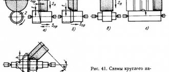
When grinding with longitudinal feed (Fig. 7.2, a), the workpiece rotates uniformly and performs a reciprocating motion. After each move or double move of the table, the circle and the workpiece come closer together. At the end of the operation, nursing is usually carried out, i.e. perform several strokes without cross feed to compensate for elastic movements.
| a b |
| in d d |
Rice. 7.2. Cylindrical grinding patterns
Rigid workpieces can be ground using the plunge method (Fig. 7.1, b), when the width of the machined surface is less than the width of the grinding wheel. With this method, the wheel moves at a constant feed until the required size of the surface being processed is reached. This method is more productive and is widely used in large-scale and mass production when processing cylindrical and shaped surfaces.
The shoulder grinding process consists of two stages - first, plunge grinding is performed with periodic movement of the table in the longitudinal direction by 0.8..0.9 of the wheel width, and then several moves are made with longitudinal feed without transverse movement to clean the surface (Fig. 7.1, V).
When face-cylindrical grinding (Fig. 7.1,d) a combined processing of a cylindrical and end surface is performed simultaneously with the feeding of the grinding wheel along the bisector of the angle or sequentially in the radial and axial directions.
When deep grinding open surfaces (Fig. 7.1, d), in one stroke the conical section of the wheel removes the entire allowance, and the cylindrical section cleans the treated surface. There is no cross feed.
Cylindrical grinding machines are characterized by a high level of precision and versatility. They are designed for external and internal grinding of cylindrical and conical surfaces, as well as for grinding flat ends of parts. This type of machines includes universal cylindrical grinding machines, semi-automatic cylindrical grinding and face cylindrical grinding machines, as well as specialized cylindrical grinding machines.
The main components of a universal cylindrical grinding machine (Fig. 7.2) are: bed 1, table 3, headstock 4 with gearbox, grinding headstock 5 and tailstock 6. The machines are equipped with a folding internal grinding spindle. For grinding conical surfaces, it is possible to rotate the grinding headstock, as well as the upper work table and the headstock, around the vertical axes.
Fig.7.2 Cylindrical grinding machine
The grinding wheel is driven by a separate motor through a V-belt drive. Circular feeding of the workpiece is carried out using another electric motor with stepless control.
The longitudinal feed movement is communicated to the lower table using a hydraulic drive; movement is controlled using devices that are switched by the table itself in its extreme positions. The grinding head is also periodically moved in the transverse direction using hydraulic mechanisms. Most machines have mechanisms for wide regulation of grinding modes and means of automating the working movements of the table and grinding headstock. It is possible to use active control devices that allow you to measure the workpiece during the grinding process, as well as devices that automatically stop the machine when the required size is reached.
When processing on cylindrical grinding machines, the workpiece is most often mounted in rigid (non-rotating) centers located on the headstock and tailstock; in this case, the circular feed is provided by a drive device connected to a rotating faceplate. It is also possible to secure workpieces in jaw chucks, and when grinding non-rigid workpieces it is additionally necessary to use steady rests.
Cylindrical grinding machine 3B161
in Moscow in St. Petersburg +7 (812) 245-28-87 in Minsk +375 (17) 246-40-09 in Yekaterinburg +7 (343) 289-16-76 in Novosibirsk in Chelyabinsk +7 (351) 951 -00-26 in Tyumen +7 (3452) 514-886
in Nizhny Novgorod in Samara +7 (846) 201-07-64 in Perm in Rostov-on-Don +7 (863) 310-03-86 in Voronezh in Krasnoyarsk +7 (391) 216-42-04
in Abakan, Almetyevsk, Arkhangelsk,
Astrakhan, Barnaul, Belgorod, Blagoveshchensk, Bryansk, Vladivostok, Vladimir, Volgograd, Vologda, Ivanovo, Izhevsk, Irkutsk, Yoshkar-Ola, Kazan, Kaluga, Kemerovo, Kirov, Krasnodar, Krasnoyarsk, Kurgan, Kursk, Kyzyl, Lipetsk, Magadan, Magnitogorsk, Maikop, Murmansk, Naberezhnye Chelny, Nizhnekamsk, Veliky Novgorod, Novokuznetsk, Novorossiysk, Novy Urengoy, Norilsk, Omsk, Orel, Orenburg, Penza, Perm, Petrozavodsk, Pskov, Ryazan, Saransk, Saratov, Sevastopol, Simferopol, Smolensk, Syktyvkar , Tambov, Tver, Tomsk, Tula, Ulan-Ude, Ulyanovsk, Ufa, Khabarovsk, Cheboksary, Chita, Elista, Yakutsk, Yaroslavl and other cities
All over Russia toll free number