Calculation of guitar differential. How to calculate?
Previously, in most enterprises, the differential guitar was considered by technologists (at least as far as I know). At the moment, at some enterprises, the differential is calculated by technologists, and at some, this “concern” has passed on to gear cutters, to say nothing of when it is necessary to “secretly” make a job! I think this is due to the fact that from mass production of gears there is a transition to production in small enterprises, where this task falls on the shoulders of the gear cutter... My personal opinion, and I have already said this more than once, is that technologists should count the differential, although this skill will not hinder the gear cutter . Of course it’s not difficult, but why the extra responsibility? I think you will agree with me. Mostly no one just wants to take responsibility!
Guitar tuning using reference tables.
Using the tables of the reference book M.I. Petrik and V.A. Shishkov “Tables for selecting gears” can quickly solve the problem under consideration. The methodology of work is described in detail and clearly at the very beginning of the book.
Standard set V.A. Shishkov contains 29 gears with the number of teeth: 23; 25; thirty; 33; 37; 40; 41; 43; 45; 47; 50; 53; 55; 58; 60; 61; 62; 65; 67; 70; 73; 79; 83; 85; 89; 92; 95; 98; 100.
Let's use this set to solve our problem.
Result of selection from tables:
Z1=23 Z2=98 Z3=70 Z4=89
u'=(23*70)/(98*89)=0.184590690
δ=|(u-u')/u|*100=|(0.184584124-0.184590690)/0.184584124| *100=0.003557%<0.01%
The invention relates to machine tool construction and can be used in various machines equipped with interchangeable gear wheels.
A guitar is known with a set of replaceable gears, containing a plate with radial and arc grooves mounted on the drive shaft, an intermediate shaft placed in a radial groove with gears that are in contact with gears mounted on the drive and driven shafts [Acherkan N.S. Metal-cutting machines, M.:, 1965, volume 1, p. 25, fig. 12]. This guitar allows you to connect the drive and driven shafts, located at some distance from each other, in a customized kinematic chain. In this case, a shaft with a pair of gears located between the drive and driven shafts makes it possible to obtain gears with variable center distances. With this guitar you can get a larger number of gear ratios.
However, in this guitar, increasing the number of gear ratios is achieved only by increasing the number of gears in the set supplied with the guitar, which requires significant costs for the manufacture of wheels. The theoretical number of gear ratios K obtained using such a guitar can be calculated using the formula from the book [Petrik M.I. Precision tuning of machine tools guitars, Moscow-Sverdlovsk, Mashgiz, 1963]:
where n is the number of replacement wheels of the guitar set.
Such guitars provide a certain range of gear ratios and a known set of gear ratios within that range.
A guitar is known with two variable center distances, with a set of gears, containing a plate with radial and arc grooves mounted on the drive shaft, an intermediate shaft placed in a radial groove with gears that are in contact with gears mounted on the drive and driven shafts, and an additional shaft having a constant center-to-center distance with the output shaft, as well as additional two pairs of gears with numbers of teeth Z1=54 and Z2=54 or Z3=36 and Z4=72, not included in the set of guitar wheels, which serve to increase the number of gears guitar numbers. The tuning method is that first, from the set of gears supplied with the guitar, wheels are installed on shafts with variable center distances, and gears from additional pairs of wheels are installed on shafts with a constant center distance [Shavlyuga N.I. Calculation and examples of adjustments for gear hobbing and gear shaping machines. — Ed. 3rd revision. and additional - L.: Mechanical Engineering, Leningrad. department, 1978. - 168 p.].
This method does not allow you to increase the number of gear ratios of the guitar without making additional pairs of gears. The theoretical number of gear ratios with this method can be determined by the formula:
where n is the number of replaceable gears in the guitar set, P is the number of possible gear ratios obtained at a constant center distance. In this case, P=3, since gears Z3 and Z4 can be swapped to produce two different gear ratios, changing the total number of gear ratios obtained by installing gears Z1 and Z2 without changing the gear ratio of the guitar.
This solution is the closest to the proposed one. The technical result of the claimed invention is to increase the number of gear ratios in a certain range without increasing the number of wheels in the set of wheels supplied with the guitar.
The problem is solved by the fact that a machine tool containing a set of gear wheels, input and output shafts, a plate with radial and arc grooves installed for rotation relative to the axis of the input shaft, an intermediate shaft with gear wheels in contact with gear wheels on the input and output shafts, placed in the radial groove of the plate with the possibility of obtaining variable center distances between the input and output shafts, equipped with an additional shaft located at a constant center distance from the output shaft with the possibility of installing various gears from the set on the output and additional shafts and ensuring the receipt of gears with a constant center distance , in which the total number of gear ratios of the guitar is determined by the formula:
where the number P is the number of possible gear ratios at a constant center distance, and the number n is the number of replaceable gears of the guitar set, reduced by two, and the problem is solved by the fact that in the method of tuning a guitar, including tuning a set of gears, where first, wheels are selected for transmission with a constant center distance, and then gears are installed on the input and output shafts, ensuring transmission with variable center distances from the remaining set of wheels.
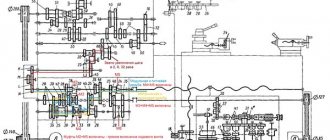
The drawing shows the structural diagram of the machine's guitar.
The machine tool includes a set of gears (not shown in the drawing), 1 - input shaft, 2 - output shaft, 3 - plate, 4 - radial groove, 5 - arc groove, 6 - intermediate shaft, 7.8 - intermediate shaft gears , 9 - input shaft gear, 10 - output shaft gear, 11 - variable center distance between the input and intermediate shafts. 12 - variable center distance between the output and intermediate shafts, 13 - additional shaft, 14 - constant center distance between the output and additional shafts, 15 - gear wheel of the additional shaft, 16 - gear wheel of the output shaft.
The proposed guitar of interchangeable gears allows you to significantly increase the number of gear ratios of the guitar while maintaining the number of wheels that are included in the set supplied with the machine. Increasing the number of gear ratios allows you to reduce the step of possible values of gear ratios compared to a guitar with two variable center distances and, at minimal additional cost, significantly increase the accuracy of tuning the guitar. The theoretical number of gear ratios K of the proposed guitar can be calculated using the formula:
where P is the number of possible gear ratios with a constant center distance, which can be obtained using gears from the set supplied with the machine by the manufacturer, and n is the number of gears in the set, reduced by two gears, which are installed on shafts with a constant center distance.
An example of determining the theoretical number of gear ratios for a 5K32 gear shaping machine, which has a set of 36 gears with the number of teeth Z: 24; 25(2 pcs.); thirty; 35; 37; 40; 41; 43; 45; 47; 48; 50; 53; 55; 58; 59; 60; 61; 62; 65; 67; 70; 71; 73; 75; 79; 80; 83; 85; 89; 90; 92; 95; 98; 100.
According to formula (2) the theoretical number of gear ratios:
Let us assume that the constant transmission center distance “a”, expressed in terms of the number of teeth, is equal to 120 (a = z1 + z2, where z1 and z2 are the number of teeth of the wheels from the set installed on the fixed shafts of the guitar). For our machine, we can get twelve reduction gears with a combination of wheels whose sum is 120 (25/95, 30/90, 37/83, 40/80, 41/79, 45/75, 47/73, 50/70, 53 /67, 55/65, 58/62, 59/61) and twelve increasing ones (the numerator and denominator in the above fractions are swapped). Thus, the value of P is equal to 24 and according to formula (2) the theoretical number of gear ratios K is equal to:
The theoretical number of gear ratios increases by more than six times, which also increases the accuracy of guitar tuning.
The proposed guitar works as follows.
The rotation of shaft 1 through a gear 9 mounted on shaft 1 is transmitted to the intermediate shaft 6 through a gear 8 mounted on it, providing an interaxle distance of 11. From the intermediate shaft 6, rotation is transmitted through a gear 7 mounted on it to a gear 10 , mounted on shaft 2, providing a center-to-center distance 12. From shaft 2, rotation is transmitted through a gear 16, mounted on this shaft, to a gear 15, mounted on a shaft 13, providing a center-to-center distance 14. In this case, the rotation speed changes (decrease or increase) shaft 1 to the rotation speed of shaft 4.
Thus, the proposed guitar makes it possible to obtain a significantly larger number of gear ratios and thereby increase the accuracy of machine settings.
Formula for calculating guitar differential:
c (machine differential) × sinβ/Mk
That is, the differential constant of the machine is multiplied by the sine of the angle being cut and divided by the module/value k - this is the number of cuts of the cutter. Usually the cutters are single-threaded, if not, then divide the module by multiplying it by 2, for example, if the cutter is double-threaded.
Guitar differential on worm wheels when cutting with a tangential feed, it is calculated using a different formula!
It’s simple, the main thing is not to make mistakes and get confused in the numbers!
Let's calculate the angle differential 10 degrees, 33 minutes, 23 seconds. Constant 15, module 8. Single-start cutter.
We find the sine of the angle 10 33 23. To do this, we convert this angle to decimal. How to do it? 23/3600+33/60+10=0.0063888888888880+0.55+10=10.5563888888889 We determine the sine of 10.5563888888889, it is equal to 0.183203128805159.
Next, we multiply the sine value by the machine constant and divide by the module. It turns out like this: 0.183203128805159×15/8=0.343505866509673
Next, open the table for selecting replacement gears (I use Petrik M.I., Shishkov V.A.) and look for the number (gear ratio) 0.343505866509673. In this case, you need to find the closest possible value. 0.3435045 is most suitable. Guitar differential: 43 • 61 83 • 92 - the first value is up, the second is down.
Setting up the differential guitar. 43 master, 92 slave. We put 43, connect it with 83, 83 on the same shaft with 61, connect 61 with 92. Like this:
I hope everything is clear to you)
Here's everything you need to know to calculate the differential, as well as how to do it on a smartphone or tablet with Android OS:
Petrik M.I., Shishkov V.A. (1973). Tables for selecting gears - download.
Sandakov M.V. — Tables for gear selection. Directory - download.
Engineering calculator for Android - install.
EBookDroid application for reading e-books on Android - install.
Share, add to bookmarks!
Source
Guitar-shaped feed box with interchangeable wheels.
Posted on March 29, 2022 Category: Mechanics |
Craftsmen, technologists and milling operators of machining shops, whose machine parks have gear hobbing machines, regularly face the issue of the most accurate selection of differential gears when manufacturing helical spur gears.
If you do not go into details of the kinematic diagram of the gear hobbing machine and the technological process of cutting teeth with a hob cutter, then this task consists of assembling a two-stage cylindrical gear reducer with a given gear ratio (u) from an existing set of replacement wheels. This gearbox is the differential guitar. The kit (attached to the machine) usually includes 29 gears (sometimes more than 50) with the same module and bore diameter, but with a different number of teeth. A set may contain two or three gears with the same number of teeth.
The guitar differential circuit is shown below in the figure.
Tuning the differential guitar begins by determining the design gear ratio (u) using the formula:
u=p*sin (β)/(m*k)
Where:
p is a parameter of a specific machine model (a number with four to five decimal places).
The value of parameter (p) is individual for each model, is given in the equipment passport and depends on the kinematic drive diagram of a particular gear hobbing machine.
β is the angle of inclination of the teeth of the cut wheel.
m is the normal module of the wheel being cut.
k is the number of passes of the hob cutter selected for the job.
After this, it is necessary to select from the set the following four gears with numbers of teeth Z1, Z2, Z3 and Z4, so that, installed in the differential gear, they form a gearbox with a gear ratio (u') as close as possible to the calculated value (u).
(Z1/Z2)*(Z3/Z4)=u'≈u
How to do it?
Selecting the numbers of gear teeth to ensure maximum accuracy can be done in four ways (at least that are known to me).
Let's briefly consider all the options using the example of a gear with module m=6 and tooth angle β=8°00'00". Machine parameter p=7.95775. Hob cutter - single pass k=1.
To eliminate errors in multiple calculations, let’s create a simple program in Excel, consisting of one formula, to calculate the gear ratio.
Link to download the Excel file: raschet-peredatochnogo-chisla-gitary-differentsiala (xls 34KB)
The estimated gear ratio of the guitar (u) is read
in cell D8: =D3*SIN (D6/180*PI())/D5/D4=0.184584124
The relative selection error should not exceed 0.01%!
δ=|(u-u')/u|*100<0.01%
For high-precision transmissions this value can be much less. In any case, you should always strive for maximum accuracy in calculations.
Dividing and running chain.
This chain connects the rotation of the workpiece and the cutter. When turning the cutter by 1 revolution, the workpiece should turn by one revolution. Estimated movements:
Rotation is carried out along the following chain: cutter, ram XII, worm gear shaft XI, VII, gear shaft VIII, gear shaft IX, guitar dividing and running shaft X, worm gear table, workpiece.
Equation of kinematic balance of a chain
Where does the division guitar tuning formula come from?
Machine 514 is equipped with a set of adjacent dividing and running wheels, data on which is given in Appendix [3. Table 6]. To facilitate the selection of replacement wheels, the number of cutter teeth, i.e. 1: 1 or 2: 1, or c = zd; c = 2zд.
???
Chain for cutting the cutter into the workpiece (radial feed).
Radial cutting of a cutter into a workpiece in machines mod. 514, 512, 5A12, 5B12, 5M14 and others are carried out using a cam, which can be one-, two- or three-pass. According to the selected cam, the workpiece is cut in one, two or three passes (depending on the material, module and required accuracy). The cam has two sections: cutting in (a, B) and running in (bc).
In the cutting area, the radius of the cam gradually increases by the amount H - the pitch of the spiral rise. When processing in one pass, after turning the cam by 90° and turning each of them (after cutting in), the table with the workpiece made one revolution. Calculated movement in a radial feed chain
Radial feed kinematic chain: shaft II, chain drive shaft IV, XIII, radial feed guitar shaft XIV, wheels EMBED Equation.3 shaft XV, worm gear EMBED Equation.3 coupling M2, shaft XVI, transmission EMBED Equation.3 shaft XVII, cam K1 radial plunge.
Kinematic balance equation:
Circular feed chain.
With a circular feed, the cutter moves along the arc of the initial circle in one double stroke. Consequently, the circular feed chain links the rotation of the cutter and the reciprocating movement of the ram.
Calculated movements in the circular feed chain:
The movement is carried out along the chain: shaft II, chain drive, shaft IV, worm gear, shaft V, bevel gear, circular feed, shaft VII, XI, worm gear, ram XII, cutter. Kinematic balance equation:
where does the formula for tuning a guitar with circular feeds come from:
where m and zд are the module and number of cutter teeth, respectively.
The machine is equipped with three pairs of replaceable circular feed guitar wheels (the sum of the teeth of each pair is 89), which allow you to obtain a range of Scr values. The appendix gives the values of Scr and the number of guitar teeth for the 514 machine with a cutter diameter of 100 mm. [3. Table 7.].
???
Workpiece requirements
The blank for the gear is made by turning. Since most gear hobbing machines provide for clamping the part in a jaw chuck, it makes sense to immediately perform turning work on a mandrel, or sharpen the workpiece with a small shank, which will be removed after cutting the teeth.
The workpiece must have the outer diameter of the gear circle at the vertices. Immediately, grooves, undercuts, and chamfers are sharpened, and light perforation is performed. As a rule, the part is no longer returned to the lathe, with the exception of workpieces with a shank or too much understatement at the ends, when the risk of deformation during milling is high.