Manufacturing
As a basis, it is proposed to take a cheap milling machine with numerical control.
To design a spindle device you will need:
- electric motor (you can use the NTM brand, series 50-50, 5800 rpm and 2 kW);
- cone-shaped shaft;
- controller for electric motor;
- 2 bearings;
- collet clamp;
- a device for determining performance, including calculating speed characteristics during rotation, inclination angles, steps. This device is called a servo tester.
The latter can be purchased at a low price; it is only important when choosing to take into account the ease of fastening
- The design of the engine has two rolling bearings. Two bearings should also be installed on the shaft using holders. A collet clamp is installed on the extended shaft to secure the cutter. This device perfectly solves the issue of lateral loads that can arise not only during metal milling, but also during wood processing.
- Installing a controller on a homemade device helps stabilize torques in cases of load changes. This is necessary during finishing operations.
The stability of the homemade spindle can be adjusted using a servo tester.
Cooling system
It doesn’t matter whether the spindle is homemade or purchased, the design must include a cooling system
- Water. The housing has holes specially designed for the passage of water. Heating the metal releases heat, which is absorbed by the water. Warm liquid is poured into a container. The latter often interferes with the maintenance and repair of the machine, so another type of cooling is most common.
- Air. Air intakes help to blow air over the heated elements. But this device also has a drawback - the filters quickly become dirty and must be constantly cleaned. But spindles installed on a milling machine with this cooling system will last much longer.
Cooling methods
Cooling of conventional electric motors is organized by blowing the fins on the housing with a fan mounted on the motor shaft. It is more difficult to organize cooling in a closed spindle housing. This can be solved in two ways - by forced blowing through ventilation grilles and channels inside the case or by using water cooling.
Water cooling is more common on industrial machines. Requires additional devices and pipelines, but cools the system much more efficiently than air.
Machine passport 2620
This operating manual “Passport of the machine 2620” contains information necessary both for the maintenance personnel of this machine and for the employee directly involved in working on this machine. This manual is an electronic version in PDF format of the original paper version. This documentation contains the Certificate and Manual (instructions) for the operation of the horizontal boring machine 2620.
PURPOSE UNPACKING AND TRANSPORTATION INSTALLATION AND INSTALLATION
- Foundation
- Machine installation
- Machine installation
PREPARATION FOR INITIAL START-UP PASSPORT
- Passport details
- Machine mechanics
- Machine equipment
- Machine controls
- Machine kinematics
- DESCRIPTION
- General structure of the machine
- Design of machine components
- bed
- Headstock
- Table
- Rear pillar
- Electrical equipment on the machine
- Accessories
- Optical devices
- Electrical equipment
- Machine kinematics
DESCRIPTION
- Main movement chain
- Feed chain
- Machine control
- Rotation
- Moving the moving parts of the machine
- Clamps of moving parts of the machine
- Machine locks
LUBRICATION OPERATING INSTRUCTIONS
- Measuring the movements of the moving parts of the machine
- Optical devices
- Precise stop mechanism based on coordinates
- Operating principle of precision stop mechanisms
- Setting the precision stop indicator scale
- Setting up rods with stops
- Threading
ADJUSTMENT INSTRUCTIONS
- Adjusting the spindle bearings
- Hollow spindle (models 2620 and 2620A)
- Hollow spindle (models 2622 and 2622A)
- Faceplate spindle
- Boring spindle
- Adjusting the gap in the screw pair of the radial support movement drive (for machines models 2620 and 2620A)
- Adjusting the thrust ball bearings of the propeller support in the tail section
- Adjusting the central overload fuse
- Adjustment procedure
- Adjustment of clamping devices
- Headstock Clamp
- Turntable Clamp
- Adjusting the clamps
- Adjusting the table rotation angle reference device every 90°
REPAIR INSTRUCTIONS
- Machine repair
- Special instructions about possible errors during repairs
The ends of the spindles are flanged for a rotary washer GOST 12593
GOST 12593-93 (DIN 55027, ISO 702-3-75). (Instead of GOST 2570-58). Metal-cutting machines. The ends of the spindles are flanged for a rotary washer and flanges for clamping devices.
This standard applies to flanged spindle ends with a short taper of 1:4 (7°7′30″) and a rotary washer for lathes and to flanged clamping devices mounted on spindle ends. GOST 12593-93 is the complete authentic text of ISO 702-3-75 “Machines. Spindle ends and faceplates. Dimensions for interchangeability. Part III. Bayonet type."
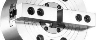
The flanged ends of type B spindles have through mounting holes around the circumference of the flange and a bayonet rotary washer, which are used to fasten the cartridge without screwing the fastening nuts, which allows you to quickly fasten and remove the cartridges. For the ends of spindles of this type (B), type 3 quick-change chucks must be used according to GOST 2675-80 Type 3.
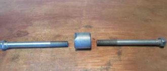
Fastening the chuck to the flange end of the spindle under the rotary washer
An example of the use of flanged spindle ends for a rotary washer
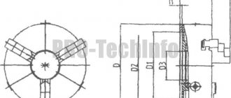
Versions of flanged ends of spindles for rotary washer
Dimensions of flanged ends of spindles for rotary washer
Lathe chuck according to GOST 2675-80 Type 3 for installation with a rotary washer
Flanges for quick-change chucks (type B) with a 1:4 cone fit (7°7′30″) for a rotary washer are made in eight conventional sizes (3, 4, 5, 6, 8, 11, 15, 20) with a nominal outer diameter 102, 112, 135, 170, 220, 290, 400, 540 mm.
Flanged ends of spindles with a rotating washer can be manufactured in three designs:
- Conventional spindle end size 3 and 4;
- The nominal size of the spindle end is 5, 6, 8;
- The nominal size of the spindle end is 11, 15, 20.
The figure shows the installation of a quick-change lathe chuck 2 on a flanged spindle using a bayonet rotary washer 1. Studs 5, which have a cylindrical thickening with a key flat in the middle part, are screwed into the end of the chuck and, when installed, are passed through the hole in the flange and rotary washer 1. After this the washer is turned clockwise and the chuck is clamped onto the spindle cone with nuts 6.
The rotary washer itself is attached to the spindle flange using bushing 3 and screw 4 (option 1) or only screw 7 (option 2), while it remains movable and can rotate on the spindle within the elongated mounting hole.
Mounting on a flanged spindle with a rotating washer takes little time, however, the flange connection ensures high centering accuracy (no backlash) and complete reliability at high spindle speeds.
Old Soviet models of wood and metal machines
Soviet equipment is still in use in production. Some people fundamentally prefer to equip their home workshops with units from the USSR.
Important!
It is sometimes difficult to find equipment or components for Soviet equipment in case of breakdown.
Screw-cutting lathe IT-1M
The lightweight machine was intended for gaining practice in workshops. Allows you to process cylindrical workpieces from the outside, drill and boring, and cut threads. Currently out of production.
Screw-cutting lathe TV-6
Appeared on the market in the 80s. It is mainly used for training future turners in workshops and training centers. Allows you to perform basic operations.
Characteristics:
- Spindle diameter - 12 mm.
- Spindle speed - 130-170 rpm.
- The distance between centers is 350 mm.
- The maximum processing length is 300 mm.
Lathes Universal 2 and Universal 3
Tabletop machines for the production of small parts. Most turning jobs are possible. The maximum diameter and length of the workpiece is 12.5 cm and 18 cm.
Lathe TSH-3
Performs the function of a sharpening and grinding unit. Suitable for use in home workshop and industrial purposes. In addition to classical turning work, the unit is suitable for finishing grinding of products and sharpening cutting and metalworking tools.
1E61M, 1E61PM, 1E61VM screw-cutting lathes
Refers to special machines that provide higher processing accuracy. All three modifications belong to the turning-screw-cutting group with a height above the centers of 175 mm.
The diameter of the processed rod does not exceed 32 mm. The maximum movement distance of the caliper is 200 mm.
Screw-cutting lathe 1М63Н
Multifunctional unit designed to perform all types of turning operations. This model also allows you to work with conical surfaces and cut multi-start threads.
The letter H in the marking indicates the ability to obtain dimensions of normal accuracy. It is possible to install additional equipment when working with large-sized workpieces.
Turret lathe 1341
The turret group machine allows processing using several tools at the same time. Available operations:
- Treatment of external and internal surfaces.
- Thread cutting.
- Drilling, countersinking, reaming.
- Working with shaped surfaces.
Processing is performed in automatic and semi-automatic mode. It is possible to produce parts from rods and piece blanks.
Screw-cutting lathe 1N65
An improved modification of the 1M65 unit. It is possible to process cylindrical and conical parts, as well as complex shaped surfaces.
Specifications:
- The height of the center above the bed and support is 500 and 325 mm.
- Spindle diameter - 128 mm.
- The maximum weight of the workpiece is 5 tons.
- The maximum diameter of the workpiece in the jaws is 870 mm.
Screw-cutting lathe 1M63
Developed in the 50s for processing workpieces made of various metals. At that time, it was a unit with unique characteristics, and it was purchased by large industrial enterprises. It ensured high quality and precision processing when turning products of any complexity.
Screw-cutting lathe 1A616
The unit was produced in the 50s of the last century. In that era, the technical characteristics were among the best. The machine is successfully used in many enterprises to this day.
The equipment is designed for a wide range of work with small workpieces. The letter A indicates particularly high processing accuracy. It is possible to cut modular, inch, and pitch threads without restructuring the kinematics.
School lathe TV-4
Developed for teaching turning in school workshops and training centers. A universal machine suitable for basic turning operations. It is lightweight and small in size, which is why it is popular in home workshops.
Metal lathe Shkolnik TV-7
The machine is manually controlled, designed for processing workpieces 100-300 mm. Supports four speed modes. Allows you to perform basic operations - external turning, boring, cutting metric threads, end processing, drilling holes. Purpose - practical training of future turners.
Tabletop metal lathe TV-16
A machine with small dimensions for performing operations of medium complexity. Available for hole drilling, thread cutting, external turning, boring.
Options:
- The distance between centers is 250 mm.
- The maximum diameter of the workpiece above the bed is 160 mm.
- The spindle hole diameter is 18 mm.
- Power - 0.4-0.5 kW.
Drilling machines for industrial use
It is enough to look at the drawings or photos of industrial drilling machines to understand that they are much more complex devices than household models. Most of the models of such machines are universal equipment that allows you to perform not only drilling in metal and other materials, but also a number of other technological operations.
Multi-spindle drilling machine GILLARDON RF 25
Production drilling machines include devices of the following categories.
Tabletop machines
Such machines are small in size and light in weight. They are used for drilling holes with a small diameter.
Vertical drilling (column) machines
These machines are used to equip small-scale and individual production. With their help, you can make holes in metal workpieces with a diameter in the range of 18–75 mm.
Radial drilling machines
This equipment is used for processing massive metal parts or workpieces in which it is necessary to form holes with centers located along a circular arc. The design of a drilling machine in this category is characterized by a fairly large overhang of the spindle unit, the value of which can reach 1300–2000 mm.
Coordinate drilling devices
The use of such machines is relevant in cases where high demands are placed on the accuracy of the location of several holes in a part.
Horizontal drilling machines
These devices process holes of significant depth (shafts, axles, rods, etc.).
Centering machines
Such equipment is used to form center holes located at the ends of the workpieces.
Multi-spindle machines
On units equipped with several spindle heads, multiple holes located in vertical, horizontal and inclined planes can be processed simultaneously.
Combined machines
On devices of drilling-milling, drilling-turning, drilling-slotting and a number of other categories, various technological operations can be simultaneously performed.
Universal drilling and milling machine Stalex-LM1450-2
The most common are vertical and horizontal drilling machines. Many modern models of drilling machines are equipped with numerical control systems, which can significantly increase the productivity of such equipment and ensure high processing accuracy. Machines with such a control system are used primarily to equip serial and large-scale production enterprises.
Among the special drilling equipment, mention should be made of magnetic machines, which are used to make holes in large parts. Such devices, equipped with a special magnetic base, are placed directly on the surface of the workpiece and are securely held on it due to a powerful magnetic field. The big advantage of machines in this category is that they can be located in any spatial position.
The unique design of magnetic machines makes it possible to process metal where it is impossible to do with conventional equipment
Despite the fact that any drilling machine can be used to make holes in workpieces made of various materials, special models are created for woodworking and furniture factories that can be equipped with one or more spindles, including rotary-type working heads. Using such equipment, you can not only make holes in wood parts, but also create nests, grooves, and remove knots.
Principle of operation
Spindle units perform two types of movement: rotational and translational. For a certain category of units, the simultaneous use of both types is provided. For example, drilling, turning, boring, milling machines simultaneously rotate the part (cutting tool) and feed it to the processing site during processing.
Spindle units of machine tools perform the same function. All spindle units of metal-cutting machines have a similar design.
The operating principle of this unit is based on receiving rotational motion from the engine and ensuring rotation of the cutting tool or workpiece. The methods of transmitting torque and fastening a part or tool depend on the adopted kinematic scheme.
Detailing of main components
The bed is designed for the correct and stable location of the main components (headstocks) during any load during operation. In metal-cutting machines, the bed can have a vertical or horizontal position. Basic requirements for a frame of any design:
- vibration resistance;
- rigidity;
- heat resistance.
Many types of machines are equipped with a traverse or cross beam that moves on vertical rails. The traverse has horizontal rails along which mobile units move. This mechanism is equipped with longitudinal milling, rotary turning, planing, radial drilling machines. Two-column vertical turning lathes are additionally equipped with a portal - a crossbar between the upper points of the racks. The portal gives the structure additional rigidity.
Guides are of great importance for the accuracy of parts; mobile units move along them.
There are several types of guides:
- rolling;
- slip;
- combined.
The guides wear out quickly, so increased attention is paid to the selection of material and manufacturing of these units. Gray cast iron, steel, bronze, plastics, composites are used
General information about the product
You may be interested in:Control cables are... Description, types and applications
This mechanism is also called a motor spindle and forms one of the key assembly units of modern wood and metalworking machines. The performance and, to an even greater extent, the accuracy of the mechanical action on the workpiece depend on its characteristics. As already noted, we are talking about a whole complex of elements that form the basis of the spindle units. Supports, lubrication system, seals, means for transmitting torque and bearing parts form the basis of this mechanism. Mainly these are components that perform supporting and auxiliary functions to ensure the operation of the attachment in the form of a cutting tool.
It is generally accepted that the power potential of machine tools primarily depends on the engine. This is true, but only partly. For example, spindle units of metal-cutting machines have their own frequency range of rotation, causing limiting conditions for cutting speeds
But it is important to understand that this range is largely a function of regulating the optimal processing rate with support for fairly high accuracy
You may be interested in: Designation of alloying elements in steel: classification, properties, marking, application
Another key function of the spindle is to directly hold the machining tool, and in some cases, the workpiece itself. For this type of fastening, special clamps and clamps are used, such as tool holders and chucks.
Therefore, when choosing equipment based on shank dimensions and determining acceptable parameters of the processing process, it is important to take into account the characteristics of the spindle
Essential elements
The most diverse elements of a technological operation are distinguished. The main ones are the following:
- Installation. This part of the technological operation, performed with constant fastening, is carried out at the very beginning. Quite a lot of attention is also paid to it, since mistakes made can cause the workpiece to shift during processing.
- Position. The completed part of the technological operation, characterized by constancy, must be carried out while fixing the position of the workpiece. It is worth considering that at this stage, the assembly of technological equipment, which is responsible for the direct fixation of the workpiece, can also be carried out.
- Technological transition. The technological transition process can be carried out within one operation without changing previously established operating modes. It is carried out in the case when processing of the workpiece cannot be completed due to insufficient functionality of the equipment. The number of transitions largely depends on how complex the workpiece is. The numbering of transitions is carried out taking into account the sequence of machining of the workpiece.
- Working progress. It is this element of the technological operation that is considered the most important, since it ensures the mechanical removal of material from the surface to give the required shape and size. As a rule, the tool moves relative to the surface of the workpiece with given parameters at a certain depth of the cutting edge into the material being processed. Also, during the working stroke, surface treatment is provided to obtain a certain roughness. The working stroke can be longitudinal or transverse, and the cutting depth and speed, as well as many other parameters, are determined. As a rule, it is longer and more precise, designed to exert a serious mechanical impact on the working body.
- Auxiliary move. It is also an integral part of the technological process. The auxiliary stroke is represented by a single movement of the tool relative to the workpiece, but this does not change the shape, size and other parameters of the workpiece. An auxiliary stroke is used in most cases to displace the main organs relative to the workpiece. An example is the supply of a tool to the cutting zone, as well as a fixing element.
- Setup. Before actual production, adjustment of the equipment, as well as the equipment used, is carried out. Setup involves installing all devices, checking the size of the tool and their position. Quite a lot of attention is paid to the adjustment process, since incorrect fixation of the tool can lead to very serious consequences. The most difficult thing is to set up CNC machines, since they must ensure high processing accuracy. In addition, often the final stage of the adjustment is control processing of the workpiece, during which accuracy and other aspects are determined.
- Adjustment. Another auxiliary process can be called adjustment, which is extremely rare. It involves the adjustment of technological equipment or the technological equipment used. In some cases, only after production has been established can it be possible to determine the incorrect positioning of tools and technological equipment.
- Technological equipment. There are also various means of supporting the procedure. This category includes materials and workpieces, as well as the required equipment. There is simply a huge amount of different equipment on sale, which significantly simplifies the task of processing workpieces of various shapes and sizes.
- Technological equipment. This definition is used to determine the technological equipment, without which it is almost impossible to process the workpiece. It can be very different and is selected depending on what procedure is being performed.
In general, we can say that a technological operation is a complex procedure that consists of a fairly large number of different parts
Basic requirements for parts
Spindles for CNC machines have the following qualities:
- rotation accuracy. The standards for axial, radial and axial runout of the front end are regulated by GOST 9726-89 clauses 3.4.12, 3.4.15 or similar imported ones;
- static rigidity. The parameter is determined by the elastic deformations of the spindle under the influence of forces arising during processing;
- wear resistance. For the manufacture of parts, alloys with a low tendency to abrasion and scoring are used;
- vibration resistance. Maximum demands are placed on high-speed CNC machines used for finishing.
Types, types, categories of spindles
Collector spindles are used for engraving and jewelry processing of miniature items. Most often these are high-speed devices with an ER8 collet with a power of about 0.8 kW. ER11 collets are more suitable for cutting and cutting soft materials. High-speed commutator spindles have proven themselves in professional and amateur use in CNC machines. Some devices are equipped with soft start systems that limit the incoming voltage. Liquid-cooled devices are often used in high-quality industrial units at enterprises in our country. The motor is effectively cooled with water or antifreeze. These spindles are equipped with high-speed iron bearings that do not require additional maintenance. These devices are controlled through frequency converters. The cutters are mounted in collets and secured with a nut. Devices from both European and Chinese manufacturers are available on the modern market.
Production of SHU in Russia
Some of the spindle components required to complete machine tools are produced by domestic manufacturers at their own machine-tool manufacturing facilities, relying on the developments and experience of Soviet industry. There are practically no problems with the manufacture of conventional drive spindle units for a milling machine or turning units that are not oriented towards high-precision processing. However, modern high-tech electrospindles are produced in Russia only in parts and based on imported components. These restrictions are associated not only with the lack of advanced technologies in this area, but also with a shortage of qualified personnel who must solve engineering, technical and production problems.
Classification of spindles by type, size and diameter
There are various bases for classification. The first, and perhaps the main one, is what equipment the unit is intended for. Of course, different machines and electrical equipment require different instruments.
The second principle of differentiation is size. The devices come in different sizes, designed for industrial use and private use. In this regard, a variety of consumable parts are needed - larger and smaller. If you want to replace the spindle on your own machine, then when purchasing you must indicate the number of your equipment, name and year of manufacture (there may be different modifications).
Well, the last, but not intended, classification is by type. Shafts can be:
- Collector. This is a device that includes a high-speed collet roller. The main areas of use are milling machines, as well as engraving operations.
- Specialized for high speeds. They allow you to achieve significant metal processing speeds, therefore increasing productivity. But since good quality can only be achieved with great precision, high-speed models are used mainly only on CNC equipment. You can buy such machines on the website.
- Design with built-in cooling. The cooling system can be supplied through a part or liquid, or cold air. This increases the cutting speed and the degree of surface roughness, and friction becomes less, so wear also comes later.
There is another classification - by manufacturer. Of course, European production is more preferable than Chinese. In Europe, porcelain bearings are often used, which provide very positive performance.
Principle of operation
Spindle units perform two types of movement: rotational and translational. For a certain category of units, the simultaneous use of both types is provided. For example, drilling, turning, boring, milling machines simultaneously rotate the part (cutting tool) and feed it to the processing site during processing.
Spindle units of machine tools perform the same function. All spindle units of metal-cutting machines have a similar design.
The operating principle of this unit is based on receiving rotational motion from the engine and ensuring rotation of the cutting tool or workpiece. The methods of transmitting torque and fastening a part or tool depend on the adopted kinematic scheme.
Lathe headstock and tailstock
Special units - turning heads - are responsible for the accuracy of installation and processing of parts in lathes. Spindle (front) headstock is a device of a lathe designed to impart rotational movement to the workpiece. The workpiece is fixed into the jaws of the chuck, collet, faceplate installed on the front end of the spindle or fixed at the centers between the headstock and tailstock. The workpiece rotation speed and direction can be adjusted from the control system.
Tailstock (thrust) - a unit of a lathe for fixing (pressing) the workpieces being processed using a thrust or rotating center. On universal machines it is also used for installing cutting tools: drills, countersinks, reamers.
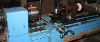
Horizontal boring machine 2620
The 2620 horizontal boring machine is designed for processing body parts that have precise holes connected by precise distances.
The largest weight of the workpiece (with a uniformly distributed load on the machine table) is 2000 kg.
This machine can be used to perform: drilling, boring, countersinking, reaming holes, turning ends with a radial support, milling with end mills and cutting internal threads with a boring spindle, as well as threading with a radial support during longitudinal movement of the table.
Due to the fact that the machine can be used in various industries for various operations, for processing various materials, maintenance of the machine should be carried out taking into account the specifics of their operation.
Electrical equipment of a surface grinding machine
The rotation of the grinding wheel on surface grinding machines is always carried out by a built-in electric motor. The vertical movement of the spindle can be carried out either manually or using a servo motor. The main advantage of using a servo motor is the presence of feedback on speed and other indicators.
Longitudinal and transverse movements of the work table can also be carried out either manually or using motors. In this case, hydraulic motors are used, as they are able to ensure the smoothest movement of the work table, without jerks or delays. Hydraulic motors are mainly used for longitudinal motion.
All KAMIOKA and L&W surface grinding machines are available in both manual and electric motor control.
Operational properties of control unit
You may be interested in:Power of one section of an aluminum radiator: features and reviews
The set of important technical and physical indicators of a spindle is not limited to rigidity and accuracy. Among other significant properties of this mechanism, it is worth highlighting:
- Vibration resistance. The ability of the control unit to ensure stable rotation without fluctuations. It seems impossible to completely eliminate the vibration effect, but thanks to careful design calculations it can be minimized, reducing the effect of sources of transverse and torsional vibrations such as pulsating forces in the processing area and torque in the machine drive.
- Speed. Characteristic of the speed of the spindle assembly, reflecting the number of revolutions per minute permissible for optimal operating condition. In other words, the maximum permissible rotation speed, which is determined by the structural and technological qualities of the product.
- Heating of bearings. Intense heat generation is a natural derivative of machining at high speeds. Since heating can lead to deformation of the element base, this indicator must be calculated during the design. The most thermally sensitive component of the assembly is the bearing, a change in the shape of which can disrupt the function of the spindle. In order to reduce thermal deforming processes, manufacturers must adhere to the standards for permissible heating of outer bearing rings.
- Load bearing capacity. It is determined through the performance coefficient of spindle bearings under conditions of maximum permissible static loads.
- Durability. A time indicator indicating the number of operating hours of a product before major repairs. Provided that the axial and radial rigidity of the spindle assembly is balanced, the service life can reach 20 thousand hours. The minimum operating time to first failure is two and five thousand hours, which is typical for grinding and internal grinding machines, respectively.
Criterias of choice
Choosing a milling machine begins with an analysis of the material it will have to work with: metal or wood.
Then technological operations and the scope of work are analyzed. When choosing a spindle, pay attention to its main characteristics:
- rotation frequency;
- power;
- design;
- speed adjustment;
- method of attaching the tool;
- work performed;
- type of cooling.
It is worth paying attention to the current connected to the equipment
Power
The choice of spindle power is determined by the hardness of the material being processed. For wood and boards made from its waste - chipboard, MDF, a power of up to 3 kW is sufficient. The equipment can process plastic, plywood, and do engraving.
Non-ferrous metals and their alloys are relatively soft, but have a high viscosity coefficient. A clean cut is obtained only with a power of up to 6 kW and a rotation speed of 18,000 rpm. Machining steel and cast iron requires a spindle with a power of more than 6 kW and a rotation speed of up to 22,000 rpm. Depending on the hardness and viscosity of the material, the modes are selected by a combination of rotation speed and feed rate.
Milling method
Milling is done in a counter and reverse manner. The rotation of the tool is directed against the movement of the part or coincides with it.
There are processing modes:
- power;
- express
In the power mode, processing occurs with a large feed, at low speeds, due to the power of the spindle. The cutting edge captures a thick layer of material every time. The high-speed mode assumes the ability of the tool to rotate at high speed. The table service is small. The mode is suitable for non-ferrous metals and wood and guarantees high cleanliness of the treated surface.
Important! Cast iron can be processed well at low speeds and low feed rates. He doesn't like high speeds.
Cooling
Milling spindles have 2 types of cooling:
- air;
- water
For cooling by air flows, special slots are made in the unit body. When the shaft rotates, turbulence occurs and cold air is drawn in from outside. The water cooling system is complex in design. It must be sealed. Air-cooled spindles installed on home equipment last longer.
On industrial equipment, bearings reduce friction and heating of the spindle. Enough air flow. The gearbox is lubricated and cooled with oil. The engine has its own cooling system - an impeller on a shaft.
Workpiece material
Cutting modes and sharpening angle of the cutting edge are selected according to the characteristics of the workpiece material.
Tree
A clean cut is obtained when processing wood with a rapidly rotating tool. Feed and cutting depth are small. The spindle is suitable for high-speed, with a power of up to 1.5 kW.
Important! When processing wood in a power mode, chips and cracks between the fibers form on the part, and the surface becomes rough.
Metal
Cutting metal requires a lot of power and high strength of the unit. During machining of a part, in addition to the torque, resistance acts on the spindle. Its force is directed perpendicular to the axis of rotation.
Metal spindles have a durable, massive body, mostly cast iron. The shaft is equipped with thrust and radial bearings. The rotation speed of the tool should be adjusted between 20–18,000 rpm.
User manual
Before using a spindle with a lathe chuck to work with workpieces at all, it is necessary to carry out a break-in, which will be discussed a little later.
After the running-in has been completed, you can begin the work itself. If bearings are used in the spindle assembly, they are lubricated with a special lubricant, which helps to use the spindle's full capabilities at high speed.
This allows the spindle assemblies to last for as long as the manufacturers allot them. The spindle is designed so that this putty can lubricate all moving parts without allowing it to escape from the bearing.
Also, thanks to the design, not only the lubricant cannot get out, but also various dirt cannot get inside the spindle assembly.
Washing must be done with careful adherence to measures to ensure the cleanliness of the workplace and tools. When washing the bearing, if extreme or excessive play is detected, as well as wear of the running tracks or chipping of the textolite separator, it is recommended to completely replace the spindle bearings.
In addition to the above, in a number of cases when the spindle has a high degree of technological load, and its operating mode is or is close to the “24-hour” category, the lubricant in the bearings should be replaced after an empirically determined period of spindle operation.
Assembly and repair
Initially, the adjustment and assembly of the spindle head is carried out in the factory, so there is no need to interfere with the design of the unit. All work is carried out in accordance with the repair documentation of the spindle head assembly. Additional adjustments can be made after a certain period of operation, when a deterioration in accuracy is noticeable. The adjustment is carried out using an adjusting washer.
Spindle repairs must be carried out by a qualified technician; their complexity depends on the type of wear:
- Neck wear. During operation, the neck becomes covered with a large number of scuff marks. You can get rid of them by grinding the neck, followed by grinding and polishing. Polishing can be done with fine sandpaper or GOI paste. When working with a grinding machine, you need to lubricate the part with oil.
The main thing is that after the repair the diameter of the neck does not decrease; if this is impossible, the neck is ground and a landing sleeve made of steel of the same grade is put on it.
- Cone wear. The most common problem that occurs due to careless handling of the machine. Wear occurs due to the tool shank turning and clogging with metal dust. The degree of wear is determined using a gauge. Several strips of chalk are applied to it, a gauge is inserted into the cone, and problem areas are determined using the erased chalk. Before testing, the cone must be cleaned and ground. If problems are found, the cone is ground or bored.
- Wear of the seat. The seat often becomes loose where the bearings are installed. To correct the problem, it is chromed or metalized. In some cases, you can install a ring and grind it to the required diameter.
- Wear of keyways. The keyway is usually adjusted to fit the required key. In some cases, a new groove is cut in a different location.
- Bearing wear. In case of severe wear of the bearings, it is best to completely change them, since it is impossible to carry out independent repairs without special tools. When using plain bearings, it is possible to gradually adjust the clearances, which significantly increases the service life.
A high-quality spindle head of a lathe, with proper operation and care, will perform its job efficiently throughout its entire operational life. The main thing is to periodically check the wear of the unit and the accuracy of workpiece processing.
What parts does the system consist of and what are the main options on the market?
First, you should understand the main features of the device and only then understand the types of structures. In fact, despite all the apparent complexity, the system is easy to use, and you can master it in a matter of days.
Device
If we consider the usual options, their main components will be the following elements:
- Bed – all components are placed and secured on it; this element is most often made massive in order to reduce vibration, ensure reliability and stability during operation. As for some options, this element may not be present in them; we are talking about tabletop devices and hand-held milling cutters;
- The work table is designed for arranging workpieces during their processing, everything is quite simple: the surface must be durable, and its area must ensure the normal arrangement of the elements being processed;
- To increase convenience, clamps are most often located on the table - for a wood milling machine, their presence is mandatory for the reason that to ensure processing accuracy, each element must be fixed as reliably and firmly as possible. If you are processing the ends, then you need a stop ruler, so you can carry out the operation very accurately and evenly;
Clamps can have different configurations depending on the nature of the work performed
- The shaft for a wood milling machine performs the function of transmitting force from the power unit to the working element; it is also often called the spindle shaft; it is located on the support. This unit allows not only to transmit force and clearly fix the element, but also to adjust the position of the working element relative to the surface of the work table, depending on the characteristics of the work being carried out;
- The spindle for a wood milling machine is used to fasten working elements and is located on the drive shaft, the main requirement for it is reliability of fixation and ease of use;
The spindle must ensure quick change of working units
To make grooves on materials, remove ends in a certain shape and do other work, special cutters for a wood milling machine are used; there are a huge number of standard sizes and configurations on the market, so you can choose the best option for any type of product;
This option, such as wood cutters for machine tools, is used for work on giving the ends a certain configuration for fastening and connecting elements
Types of equipment
There are currently several main options on the market:
- CNC machines are the most high-tech option; their distinctive feature is the presence of a processor that allows you to process information and work according to predetermined parameters. This ensures the highest processing accuracy and a minimum of flaws, because you don’t have to do everything yourself, the whole process is controlled by a computer;
- Horizontal equipment has a work table and, accordingly, processes workpieces in a horizontal plane. In vertical installations, the working unit is located in a vertical plane and can move up and down, which simplifies the processing of some elements;
- Manual milling machines can hardly be called machines, but they are affordable and can handle most small jobs. In addition, with their help, you can build a small stationary device; in this case, the diagram of a wood milling machine will be a structure for attaching the tool, which may also have a copier to make products according to the sample;
In this case, you don’t even need a drawing of a wood milling machine with your own hands - you need to make a system for fastening the equipment and think about fixing the workpieces
Desktop options are most often intended for domestic needs and are good solutions for reasonable money.
Each wood cutter for the machine has its own configuration, it is advisable to have on hand a whole set with the most popular options
Main design features
A universal screw-cutting lathe consists of main structural units, which are standard elements. These include:
- caliper;
- bed;
- thrust and spindle headstock;
- electrical equipment;
- drive shaft;
- guitar gears;
- a box that provides selection and change of feeds;
- lead screw - it is this detail that distinguishes a screw-cutting lathe from a standard lathe.
Depending on some features, the accuracy of the machine may vary. Therefore, universal equipment can be of both accuracy class N and increased – P.
Front and rear stock
The headstock or spindle has the main role of fixing the workpiece in processing and transmitting rotation to the workpiece from the electric motor.
The spindle is located inside the body of the headstock. A speed control handle is mounted on the outside of the machine body. The tailstock or thrust is necessary to fix the workpiece.
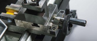
Caliper
The support is designed to move the tool holder with the cutter in the longitudinal, transverse direction relative to the axis of the machine. The lower part of the support is called the slide or carriage.
After a certain time of operation of the machine, the support will need to be adjusted, since otherwise the processing speed will decrease. Adjustment for gaps consists of tightening the wedge strip.
Compared to other parts, the caliper is large. The choice of tool holder is determined by the class of the machine. For large equipment, be sure to secure the cutters with an additional four screws.
Gearbox
This is the main part of the spindle drive. It transmits engine energy to the rest of the machine. Another function is to change the spindle speed and the operating speed of the entire machine.
The box is built into the spindle head housing or in a separate housing block. The speed can be changed in a stepless or stepwise manner. The standard gearbox includes the following components:
- gear system;
- V-belt transmission;
- reversible electric motor;
- electromagnetic clutch with braking system;
- handle for changing gears.
The gearbox operates using gears.
Spindle
This is the main part of the machine, which is made in the form of a shaft with a conical hole for securing workpieces. To ensure that the part has high strength and durability, it is made of high-strength steel.
In the classic version, the spindle is made on high-precision rolling bearings. A special ring is installed on the support of the part, which ensures the accuracy of the machine.
There is a conical hole at the end of the structure. The spindle needs a cavity to install a rod that helps, if necessary, knock the center out of the seat.
The strength and durability of the spindle directly depends on the bearings available there.
bed
This is the main part of the machine, which is made using cast iron. All the most important parts and elements of this design are attached to it.
The frame itself consists of two steel beams. The beams, in turn, are connected to each other by stiffening ribs. Each beam has a connection to two guides.
The guides on both sides belong to the prismatic group. The flat-shaped guide is located inside on the left side.
Threading
There are several ways to cut threads using a screw-cutting lathe. For this, a die, tap, cutter and other types of tools are used.
With their help it is possible to cut internal and external threads
When using a cutter, it is important to fully comply with the technology. It includes:
- correct sharpening of the cutter;
- accurate adjustment of machine operating modes;
- using a template, correct installation of the cutter in the center of the part;
- measuring the resulting dimensions using gauges or templates.
In such work, defects in the form of sharp points, torn threads, scuffing and crushing are unacceptable.
Electrical control unit
The standard control unit for a screw-cutting lathe includes several handles and buttons:
- handle for setting the number of revolutions;
- control system for setting cutting surface parameters;
- handles for caliper control.
A CNC machine has a more complex structure, but can work without operator participation at intermediate stages.
Apron
In the apron of a screw-cutting lathe there are mechanisms that convert the rotational movement of the lead screw and the lead shaft into the translational movement of the caliper.
Classification
Due to the large number of spindle models, there are several types of classification. The most common type is classification by technical characteristics. By purpose they are divided into:
- CNC machines with two spindles designed for milling;
- vertically rotating elements for manual processing of products with complex shapes;
- electric rotary spindle (can be made by yourself);
- vertically rotating elements of electric type (made by hand, but have low productivity);
- element for working with the end part.
Depending on the application, there are several most commonly used spindles. One such device is an engraver. It has a low cost, but is installed on a machine made by yourself. The disadvantage of such a device is the complex processing of metal products. The reason for the lack is weak torque. Therefore, the engraver is recommended to be used when processing soft wood.
Bormashinka
A more expensive spindle option. Unlike an engraver, torque is maintained regardless of speed. The advantage of this option is the cartridge clamp, which is of high quality. The drill is characterized by a quiet sound of operation.
DC – motor
A device with high performance. During operation, it does not create strong beating or loud sounds. Milling machines for such a device are easy to make with your own hands. The presence of CNC makes it possible to regulate the number of revolutions. The disadvantage of the unit is its rapid heating when processing the material. The device should be cooled periodically. Recommended for processing soft workpieces.
Straight grinder
Equipment capable of performing spindle tasks. The device has high performance and is able to cope not only with wood, but also with metal. The disadvantage of the unit is the high noise level during operation. The number of revolutions cannot be adjusted, since the configuration does not include an electronic device that performs this task.
Milling cutter Sparky
Milling element capable of being used as a rotary spindle. Not all routers can be used for this purpose. But devices of this brand have high power, speed control and performance. These advantages are enough to use the device for processing different materials. During operation, the parts heat up slowly, which ensures safety and a low risk of fire.
Kress router
Another milling element of high quality at an affordable price. The devices are used in conjunction with CNC systems. The package is equipped with an additional system to ensure stable beating.
Professional spindle
An element designed specifically for the milling machine. The unit is liquid cooled. It is characterized by a high level of reliability and accuracy. During operation, the device does not create loud sounds. The disadvantage of the equipment is its high cost. The cooling system must be equipped with a frequency converter, which costs almost as much as the device itself.
Drilling tool
To secure cutting tools (drills, reamers, countersinks, taps), special chucks and intermediate devices are used, and if the dimensions of the tool allow, they are installed directly into the spindle.
The mounting holes of machine spindles are standardized. As a rule, they have a conical shape (Morse taper).
If the cone of the cutting tool shank has a different cone from the cone of the spindle of a vertical drilling machine, then adapter bushings are used. For example, a drill is attached to a sleeve, and the sleeve is mounted in a spindle seat. If it is necessary to secure a cylindrical drill, then split bushings are used: they have a cylindrical hole on the inside and a conical hole on the outside.
Drill chucks are more universal because... It is easier and faster to secure a cutting tool in them, and if they are quick-clamping, this also reduces time.
Spindle design features
A key design feature of any type of spindle is the use of support bearings in the design, which hold the shaft in the working position (horizontal or vertical) and prevent its radial runout. Cheap spindles are usually equipped with the simplest rolling bearings. Units that are subject to strict requirements for minimizing radial runout are equipped with hydrodynamic plain bearings. High-speed precision machines use hydrostatic and magnetic supports that provide axial deviations of no more than 0.5 microns. Such bearings are used in most CNC machines today.
Another feature of the spindle design is the presence of its own cooling system. Since the spindle is mechanically directly coupled to the workpiece or tool being processed, the heat generated during the metalworking process is absorbed by the clamping device and shaft, which causes thermal deformation of the spindle components. This effect is prevented by the cutting fluid that washes special technological cavities inside the spindle, thereby eliminating the conditions for the occurrence of deformations.
Device
The spindle is a steel shaft, in front of which there is a mount for the working tool. In the classic style, the spindle is mounted on high-precision rolling bearings. To ensure the required accuracy of operation during operation, a special ring is installed on the spindle support. The ring is adjusted using an adjusting nut, which, when tightened, moves the nut along the spindle, which ensures the elimination of gaps formed during operation.
The design of the spindle depends on many factors, usually on the application, the type and design of the machine, the size and speed of operation. Previously, the basis of this unit was bearings, the deviation on which reached 1 micron. Today, the requirements for spindles have increased, so modern samples are made using magnetic or air supports. This solution makes it possible to achieve a minimum deviation not exceeding 0.2 microns.
For higher precision, at which the processing error is below 0.03 µm, a special drive method is used. The spindle is driven and accelerated by the flywheel, but the work is performed after the flywheel is turned off and the spindle operates due to inertia.
The design of the unit must meet the following requirements:
- Accuracy. It is selected based on the machine model, the material being processed and technological requirements.
- Speed. Different types of spindles rotate at different speeds, the faster the speed of processing the workpiece, the higher the quality of the work performed.
- Rigidity. It is determined by the ratio of the spindle deflection and the level of radial runout. The lower this indicator, the higher the quality of work.
- Durability. The service life of the unit primarily depends on the quality of the bearing used.
- Vibration resistance. The spindle must be vibration tolerant to the external vibration of the machine, which ensures high precision of the tool.
- Permissible heating. It is determined by the maximum heating temperature of the unit at which the operating characteristics of the spindle do not change.
- Load bearing capacity. Characterizes the recommended weight and dimensions of the working tool.
Typically the spindle is not considered as a separate structure. Most often, the entire complex of a screw-cutting lathe is considered, including an electric motor, drive, headstock and spindle. The electric motor can be changed, even power plants operating on direct current can be used. The main thing is that all components correspond to the electrical circuit of the machine.
Spindle unit calculation
Stiffness is considered as the main design characteristic. It is expressed by the indicator of elastic movements in the processing zone under the total effective force from the own elastic deformation of the spindle with its supporting elements. To determine the characteristics of heavily loaded components, the strength indicator is also used, and for spindle heads with high speeds, the key factor for successful processing will be the minimum resonance indicator, that is, high vibration resistance.
Almost all spindle units for metal-cutting machines are separately calculated based on cutting accuracy. This calculation is performed for bearings based on the radial runout coefficient of the spindle end. The permissible runout indicator depends on the designed accuracy class, the definition of which is based on the requirements for the processing process.
The radial runout indicator on the inner surface of the bearing ring depends on its eccentricity and the errors of the tracks with the rolling elements. This accuracy parameter is expressed through the effect of the so-called wandering beat. In the process of monitoring bearings, their compliance with established standards is determined, after which, if deviations are identified, the products can be sent for revision. Among the measures to further improve the accuracy of the bearings for the spindle assembly during assembly, the following can be identified:
- The eccentricities of the inner rings and journals of bearings are located in opposite directions.
- The eccentricities of the outer bearing rings and housing holes are also located in opposite directions.
- When installing the eccentricities of the inner rings of the rear and front bearings, their location should be maintained on the same plane.
Detailing of main components
The bed is designed for the correct and stable location of the main components (headstocks) during any load during operation. In metal-cutting machines, the bed can have a vertical or horizontal position. Basic requirements for a frame of any design:
- vibration resistance;
- rigidity;
- heat resistance.
Many types of machines are equipped with a traverse or cross beam that moves on vertical rails. The traverse has horizontal rails along which mobile units move. This mechanism is equipped with longitudinal milling, rotary turning, planing, radial drilling machines. Two-column vertical turning lathes are additionally equipped with a portal - a crossbar between the upper points of the racks. The portal gives the structure additional rigidity.
Guides are of great importance for the accuracy of parts; mobile units move along them.
There are several types of guides:
- rolling;
- slip;
- combined.
The guides wear out quickly, so increased attention is paid to the selection of material and manufacturing of these units. Gray cast iron, steel, bronze, plastics, composites are used
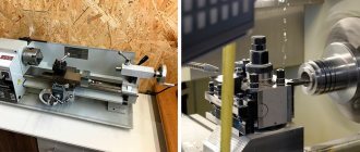
Spindle unit
spindle assembly of a machining center
This mechanism is one of the most important in a lathe; it provides the main movement - cutting. The spindle assembly is located in the headstock and can have a different design.
Main parameters of the headstock spindle assembly:
- accuracy - determined by the degree of runout, which must be within certain limits. The runout values are set taking into account the accuracy class;
- Vibration resistance is the main dynamic unit that causes vibrations of the headstock and the entire machine. Vibration resistance is determined by the oscillation frequency of the spindle end and should be more than 600 Hertz for particularly precise models, and more than 250 Hertz for ordinary ones;
- stiffness - being a component of the supporting system, the spindle affects the total stiffness;
- Heat Resistance - The spindle supports located in the headstock are the main source of heat generation in the machine. From the supports, heat gradually spreads along the walls of the headstock, causing it to skew relative to the base;
- durability - it depends mainly on the type of support and determines the life of the spindle without loss of accuracy.
Video about the exact dimensions of components and parts of a lathe:
Accessories for household drilling machines
A tabletop drilling machine intended for use at home can be equipped with additional devices that significantly increase its functionality and ergonomics.
Machine "Caliber SS-13" with an additional lifting work table
Let's list such devices.
- The work table, which is mounted on a cantilever stand, allows you to perform various actions with it: raise and lower it manually (in the simplest models of machines); use a special handle connected to a rack and pinion mechanism to change the height of its location; fix at the required height. Some models of drilling machines for home can be equipped with a work table, which can not only move in the vertical direction, but also rotate about the vertical axis.
- The mechanism that provides adjustment of the drilling depth operates on the following principle: the tip of the drill, fixed in the equipment chuck, is lowered to a mark on the side surface of the part corresponding to the required drilling depth. After this, tighten the tightening lever of the depth regulator, thereby limiting the stroke of the cutting tool.
- The protective screen, which is a folding guard made of transparent plastic, protects the machine operator from flying chips and prevents clothing and long hair from entering the processing area.
Quick release clamp for drilling machine BOSCH PBD 40
How to make it yourself?
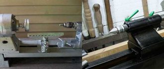
To make a spindle with your own hands, you should prepare the parts:
- extended shaft;
- bearings;
- brushless motor;
- controller;
- pulleys;
- body with machined seats.
The body is machined from the inside, and seats for the bearings are machined. A mount for the electric motor is made outside. The spindle shaft with bearings mounted on it is installed in the housing and secured with pass-through covers to prevent axial movement. The engine is installed externally. Rotation is transmitted through a controller to adjust the speed and belt drive.
The technical characteristics of the spindle determine what can be processed on the machine and what operations can be performed. When making a milling machine at home, you can use an engraver, a grinder and a drill as a milling unit. More powerful equipment for metal requires the manufacture of a durable spindle.
Edge processing - working with a template
It’s easier and faster to process the edges of a regular board using a surface planer, but if you don’t have one, a hand router will also do the job, but it will just take more time. There are two ways: without a template and with a template. If this is your first experience with a router, it is better to use a template. When processing the edges of boards, you need straight edge cutters, and most likely you will need two - with a bearing at the beginning and at the end of the cutting part (pictured).
To process the edge - make a flat surface
As a template, you can use an already processed board or, for example, a building rule. The length of the template should be slightly longer than the length of the workpiece - 5-6 cutter radii on each side. This will make it possible to avoid the cutter “diving” into the material at the beginning and at the end. One important point: the horizontal plane (perpendicular to the one being processed) must be level. In any case, its curvature should not be greater than the gap between the bearing and the cutting part, otherwise the cutter will touch the template, and this is very bad - it becomes imperfect and the applied irregularities will appear on other copies.