Purpose.
The self-centering three-jaw lathe chuck belongs to the class of spiral-rack self-centering three-jaw chucks with a cylindrical belt and mounting on a lathe through an intermediate flange.
Self-centering spiral rack lathe chucks are designed for installation on universal lathes, turrets, and internal grinding machines. They are used in conditions of single, small-scale and mass production. Three-jaw self-centering chucks hold round and hexagonal workpieces or round rods of large diameter. Unlike wedge-type lathe chucks, they do not require time for readjustment in the case when installation to a different clamping diameter is required.
What to look for when choosing?
To fix axisymmetric workpieces on the machine, you need to use a self-centering three-jaw lathe chuck, and for asymmetrical parts, chucks with independent jaws.
The following parameters are also taken into account:
- the magnitude of the design load;
- method of fixation on the spindle axis;
- machine operating frequency limits;
- cartridge accuracy;
And, of course, our customers pay attention not least to the price of three-jaw lathe chucks.
Specifications.
The chuck body is made of high quality special cast iron
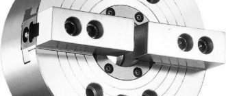
Fig. 1 - General view and main dimensions of a three-jaw lathe chuck.
Technical characteristics of the lathe chuck are given in Table 1
Table 1
| Name of parameters | Values |
| Outer diameter D, mm | 250 |
| Diameter of connecting belt D2, mm | 200H7 |
| Diameter of hole in housing D1, mm | 76 |
| Diameter of mounting holes, mm, D3 | 224 |
| Outer diameter of the product clamped in straight jaws, largest mm | 120 |
| Outer diameter of the product clamped in the return jaws, largest mm | 266 |
| Maximum permissible rotation speed, min ' | 2000 |
| Flange side height | 5 |
| Chuck height without jaws | 85 |
| Height of chuck assembly | 119 |
| Cartridge weight, kg | 29 |
| Fasteners | 6 M12 bolts |
Using a lathe chuck, using straight and reverse jaws, you can clamp workpieces in the following range of sizes
The straight cam is designed to secure the workpiece to the outer surface of the shaft or to the inner surface of the hole in the workpiece. The reverse cam is designed to secure the workpiece to the outer surface.
Accuracy characteristics of lathe chuck
Fig.2.1 - Lathe chuck at idle speed
the cartridge provides the following accuracy characteristics: Radial runout a – 0.045 mm;
End runout c – 0.025mm.
By securing the workpiece in the chuck, the following characteristics can be achieved:
Scheme I:
Rice. 2.2 - Lathe chuck with straight jaws attached to the outer surface of the workpiece.
range of fixed workpieces from 5 to 118mm;
Radial runout a at a length of 80 mm is 0.040 mm.
Scheme II:
Rice. 2.3 - Lathe chuck with workpiece fastened to the outer surface with reverse cams.
range of fixed workpieces from 77 to 188 mm and from 160 to 250 mm;
Radial runout a – 0.045mm;
End runout c – 0.025mm.
Scheme III:
Rice. 2.4 - Lathe chuck with workpiece fastened to the inner surface with straight jaws.
range of fixed workpieces from 62 to 174 mm and from 145 to 256 mm;
Radial runout a – 0.045mm;
End runout c – 0.025mm.
Lathe chucks BISON-BIAL Poland 3-jaw self-centering spiral with manual clamping
Scientific and technological progress in all sectors of social production means the continuous development and improvement of tools and objects of labor, the creation of fundamentally new machines, materials, energy sources, technological processes, as well as related progressive forms of production organization.
The leading role in solving these problems belongs to mechanical engineering, which creates the most active part of fixed production assets and largely determines the pace of technical progress, the growth of social production and its efficiency.
Mechanical engineering products ensure the creation of not only our own technological base, but also a technological base for other industries, and also largely determine the level of development of the country's socio-economic system and its national security.
An important and integral part that serves for the uninterrupted supply of products to the engineering industry are lathes, screw-cutting lathes, drilling, boring, milling and other machines.
BISON-BIAL lathe chucks are an integral part of all lathes; the number of their design varieties is very large. Below is a conceptual diagram of the BISON-BIAL lathe chuck :
Possessing a powerful but sensitive mechanism, the BISON-BIAL lathe chuck allows you to securely fasten parts with high accuracy of their centering, both for high-speed processing and for more delicate work.
The BISON-BIAL lathe chuck can be installed on the spindle of a machine tool or device either directly on a tapered end fit or through adapter flanges.
BISON-BIAL lathe chucks with standard mounting bases to any other various spindle mounting bases, in particular threaded ones.
Also used in the standard version are mounting cartridges on Morse cones of various numbers. There can be any number of non-standard options for attaching cartridges to the spindles of different machines and mechanisms.
Self-centering lathe chucks can be of 4 types of fastening:
1) on a flange (with a cylindrical centering collar) - GOST 2675-80 , GOST 3889-80 , DIN 6350 ;
2) on a cone for a rotating faceplate - GOST 2675-80 , GOST 12593-93 , DIN 55027 ;
3) on a cone with through fastening - GOST 2675-80 , GOST 12595-2003 , DIN 55026 ;
4) on a cone with Camlock fastening - GOST 26651-85 , DIN 55029 .
According to design, there are BISON-BIAL lathe chucks with solid hardened jaws (version 1) and with assembled jaws (version 2) .
Solid straight jaws SJZ allow you to clamp the workpiece from its outer side, reverse hardened jaws SJW clamp the workpiece from the inside. Solid hardened cams are made from forgings with a tensile strength σB of at least 500 MPa and heat treatment of the clamping and rubbing working surfaces to a hardness of at least 43 HRCE.
For non-standard machined parts, raw SGM cams or linings are used. The turner gives the raw cam the necessary configuration in accordance with his needs, then hardens it.
The assembled jaws consist of a hardened SP rack (main jaw) and a top jaw. They are more often used when it is necessary to frequently change direct/reverse jaws, or in BISON-BIAL lathe chucks with a large outer diameter, where frequent changing of jaws is difficult due to inconvenience, the large mass of the chuck and the jaw itself.
On lathes, two-, three- and four-jaw turning chucks BISON (BISON-BIAL) with manual and mechanized clamping drive are used.
In two-jaw self-centering lathe chucks BISON (BISON-BIAL) various shaped castings and forgings are secured; The jaws of such lathe chucks BISON (BISON-BIAL) , as a rule, are designed to secure only one part.
In three-jaw self-centering lathe chucks BISON-BIAL (BIZON-BIAL) workpieces of round and hexagonal shapes or round rods of large diameter are secured. They are the most popular due to the speed of centering and clamping of parts, which is important for small-scale production.
In four-jaw self-centering lathe chucks BISON-BIAL (BIZON-BIAL) rods of square section are fixed, and in chucks with individual adjustment of the jaws - parts of rectangular or asymmetrical shape.
The most widely used three-jaw self-centering lathe chuck of the Polish plant BISON-BIAL (BISON-BIAL) model 3534-250-6 (3-spiral chuck; 5-3-jaw/steel body; 3 – type C fit according to DIN 55027; 4 – solid jaws (SJZ – straight and SJW – reverse); 250 – diameter of the lathe chuck and fit on a conventional Morse taper – 6 , total lathe chuck BISON-BIAL (BISON-BIAL) 3534-250-6 , you can also consider this way any BISON-BIAL lathe chuck (BISON-BIAL) and decipher its markings, below is a table of codes of Polish BISON-BIAL lathe chucks (BISON-BIAL) , all running models of BISON-BIAL lathe chucks (BISON-BIAL) and standard sizes are widely presented on warehouse of RDA Group LLC in Moscow .
The main part of the three-jaw chuck BISON-BIAL (BISON-BIAL) with manual clamping is a body made of cast iron or steel. BISON-BIAL lathe chucks with a steel body are more expensive, but they can withstand higher rpm compared to a cast iron body.
In the inner part of the body of the BISON-BIAL lathe chuck there is a part, one end of which is made in the form of a bevel gear, and at the other end an Archimedean spiral is cut. This part is called a spiral disk, which is also called in technical jargon - Archimedean spiral, spiral, snail, planetary.
As a rule, the BISON-BIAL lathe chuck has two sets of - straight jaws SJZ for fastening parts in compression and expansion, and reverse jaws SJW for fastening parts with large diameters in compression. Many manufacturers include in the standard set of the BISON-BIAL lathe chuck (BISON-BIAL) or supply separately a set of SP cam racks on which nozzles made of non-hardened steel of any shape can be attached.
These replacement attachments are commonly called wet cams.
In terms of centering accuracy, cartridges can be of different classes. Class 1 according to DIN standards or class “A” according to GOST 1654-86 are the highest in accuracy.
Chuck jaws , for example, a diameter of 250 mm , with maximum hand effort, develop a pressure of up to 4.5 tons. A disproportionate clamping force on the chuck can lead to defective parts, expressed in the crushing of its finishing surface, deformation of a thin-walled part, or it can simply break the fragile material of the part.
The other side of the disproportionate force, namely insufficiently reliable clamping, can lead to the part being torn out of the jaws by cutting forces or to the part turning in the jaws.
Therefore, different clamping forces should be applied to parts depending on their processing conditions.
The chuck jaws have a serial number, the same as the grooves in the BISON-BIAL lathe chuck in which they are installed. The numbers of the cams are stamped on the non-working surfaces of their grooves, and the numbers of the cartridge sockets corresponding to the cams are stamped on the inner ends of the cam grooves. In addition, the numbering of the cams is indicated by the size of their inlet part on the comb. The first cam has a smaller lead-in value and as the lead-in size increases, the numbering increases. When the key is rotated counterclockwise, the cams disengage with the Archimedean spiral and are easily removed from their grooves.
Device and principle of operation.
3.1. The design of a spiral rack lathe chuck is shown in Fig. 3.
Fig. 3 - Design of a spiral rack lathe chuck.
Cams 1 , 2 and 3 of the cartridge move simultaneously using disk 4 . On one side of this disk there are grooves (shaped like an Archimedean spiral) in which the lower protrusions of the cams are located, and on the other there is a cut bevel gear mated to three bevel gears 5 . When you turn one of the wheels 5 disk 4 (thanks to gearing) also turns and, by means of a spiral, simultaneously and evenly moves all three cams along the grooves of the cartridge body 6 . Depending on the direction of rotation of the disk, the cams move closer to the center of the chuck or move away from it, clamping or releasing the part. The cams are made in three stages and are hardened to increase wear resistance.
❓ Frequently asked questions:
⭐ Tell me the options for cartridges for work that needs to be done from two installations (and quite accurately in terms of runout).
You can use parts from the Polish manufacturer Bison-Bial. For example, the 3504-80 lathe chuck allows you to avoid excessive vibrations at high speeds. The radial runout of the housing is up to 0.010 mm. Also suitable for this work is the premium 3-jaw turning chuck KFD HE-170. It is characterized by high accuracy of radial and axial runout. Depending on the diameter of the chuck, it is capable of operating at frequencies from 3500 to 8000 rpm.
⭐ A chuck is needed for clamping and machining pipes on a lathe. How to choose the right diameter?
To work with workpieces of different sizes, chucks of different sizes are produced. To buy a three-jaw chuck for a suitable type of lathe, you need to consider the following:
- machine model;
- method of clamping the pipe - by external or internal diameter;
- placement of the pipe - it will pass through the cartridge or will be fixed by the edge.
Based on these data, as well as taking into account the recommendations for fastening pipe blanks for a specific machine model, the diameter of the required chuck is selected.
Hydraulic milling chucks: pros and cons
The hydraulic chuck is one of the most advanced types of equipment for a milling machine, having a very high clamping force. The hydraulic chuck is accurate, versatile and easy to use. Let's compare it with analogues.
How does a hydraulic chuck work?
In the hydraulic chuck, the tool is clamped due to the pressure of the liquid inside. To clamp or release, you need to turn the screw located in the side surface of the cartridge.
When the screw is not screwed in, the pressure inside the cartridge is close to atmospheric. As the screw is tightened, the pressure increases, thereby reducing the inner diameter of the chuck and holding the tool firmly in place.
Advantages and disadvantages of a hydraulic chuck relative to other types of equipment
Hydraulic chuck
vs collet chuck
If we compare a hydraulic chuck with a collet chuck, then, of course, in the first version the clamping forces will be many times better.
The fluid pressure is evenly distributed inside the hydraulic chuck and ensures compression of the tool over the entire surface without any distortion. As a result, the runout does not exceed 3 microns, which is several times less than when the tool is clamped in a collet chuck.
However, a more advanced design could not but affect the cost - the price for a hydraulic chuck is much higher than for a collet chuck.
Hydraulic chuck
vs Weldon
chuck The hydraulic chuck is comparable to the Weldon chuck in terms of ease of use. Indeed, in both cases, in order to fix the tool, you only need to tighten the screw.
However, if the Weldon chuck works according to the principle: the harder you clamp, the tighter it will hold, then in the hydraulic chuck you don’t have to bother with this issue - just bring the screw to the limit stop.
Hydraulic chuck
vs thermal chuck
In terms of clamping characteristics, hydraulic and thermal chucks are comparable. However, for a thermal chuck, you will need a special device to heat and cool the tooling. In this regard, the hydraulic chuck is more versatile.
Disadvantages of hydraulic chucks
1. The hydraulic chuck is designed for a tool with a specific size. However, this problem can be solved by using adapter bushings.
If you need to install a tool of a smaller diameter, then it is enough to add an adapter collet-sleeve to the design.
2. Clamping a tool with a flat into the hydraulic chucks must be done with great care and based on the recommendations of the hydraulic chuck manufacturer. In the catalog he will definitely indicate the possibility of using such a tool. Otherwise, the structure of the equipment may be damaged.
3. There is a possibility of breakage when the hydraulic chuck is clamped idle. It is strictly prohibited to tighten the screw into working position without a tool installed.
4. When machining at high speeds, it is necessary to use coolant, since the liquid inside the hydraulic chuck may boil.
Unique feature of the hydraulic chuck
The liquid inside the hydraulic chuck significantly dampens vibrations, which cannot be avoided during processing. This helps reduce wear on the machine spindle. In addition, the working tool will serve you much longer, and the likelihood of microchips on the cutting edge will be minimized.
For help with the selection of tooling, please contact the managers of TIGROTECH by phone +7
. Prices and availability can be found in our catalogue.