Neodymium magnets have incredible attractive force. The larger the magnet, the higher its power. It is this quality that allows them to be used in many industries. However, if such a magnet becomes attached to a metal object, it will be problematic to remove it without the appropriate skills and knowledge. So, let's figure out how to remove a neodymium magnet from metal, and what is needed for this?
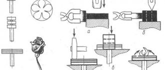
Demagnetization of pipes before welding
Welding pipes and steel structures using direct current is often accompanied by the effect of “magnetic blowing,” which is caused by residual magnetization.
At the same time, the stability of the process deteriorates, metal spatters, defects such as pores, lack of fusion, lack of penetration, slag inclusions form in the weld, and sometimes welding becomes simply impossible due to arc failure and electrode sticking. The main reason for the magnetization of pipelines is the use of magnetic flaw detectors to diagnose their technical condition, after which the magnitude of the residual magnetic field in the cutting of a welded joint can reach 100-150 mT (1000 - 1500 Gas) or more. Additional factors contributing to the magnetization of pipelines are the Earth's magnetic field, elastic mechanical stresses, and technological magnetization of pipes during their manufacture and transportation. Since the magnetization of pipes does not allow obtaining a good quality weld, demagnetizing them before welding is a necessary technological operation. It is almost impossible to achieve complete demagnetization, therefore welding is allowed with insignificant residual magnetization, which does not have a noticeable effect on the welding process. For example, the STO Gazprom standard 2-2.2-136-2007 “Instructions on welding technologies for the construction and repair of field and main gas pipelines. Part 1" established that the residual magnetization of the ends of pipes and pipeline connecting parts should be no more than 2 mT (20 G). When magnetization is more than 20 Gauss, demagnetization must be performed. Degaussing devices type RU
Since 1997, the Kharkovneftemash Association, together with NPP Spetsmagnitproekt LLC, has been producing highly efficient and reliable pipeline demagnetization devices of its own design, such as RU, which are successfully used during repair and installation work in the field by oil and gas transport enterprises: "Dnieper Trunk Oil Pipelines", " Main oil pipelines "Druzhba", "Prikarpattransgaz" (Ukraine), JSC "KazTransOil", "KazTransGas" (Kazakhstan), LLC "Volgotransgaz" (Russia), etc. The equipment is certified, manufactured according to TU U31.2-30140615-001-2001 . RU-type devices are designed for local demagnetization before welding of both joined pipes with a diameter of 377-1420 mm and their free ends, and, if necessary, can be used for demagnetization of other ferromagnetic products. The resulting demagnetized state is resistant to mechanical stress and is guaranteed to remain until welding. Currently, two new models of demagnetizing devices are being mass-produced: RU-E and RU-S, which differ in the type of input voltage: RU-E is powered from a direct current source (welding rectifier, unit, stabilized voltage source), and RU-S is powered from a source alternating current voltage 380V, 50Hz (mobile power station). Otherwise, their technical characteristics are similar.
Advantages • simplicity and ease of use; • demagnetization is carried out before welding, and both pipes joined for welding and free ends can be demagnetized; • short demagnetization time (no more than 20 minutes with installation and dismantling of cables); • the demagnetized state remains for a long time; if it is necessary to re-join the pipes, additional demagnetization is not required.
Composition • power unit (1) with remote control panel (3); • electromagnetic compensator (2) – a set of 5-6 cable sections with connectors; • magnetometer (4); • for RU-E (at the customer's request) power source (5) - inverter welding rectifier type ABC-315M or DC source IST-1.
RU-E RU-S
Description The essence of the demagnetization technology, implemented using a device of the RU type, is that with several pulses of a magnetic field, the magnetization of the pipe near the welded edges is stabilized and brought to a value that is less than the value that has a harmful effect on the quality of welding. The pulses are generated in the power unit (1) and transmitted to the electromagnetic compensator (2) - several cable sections wound onto the pipe at the joint or at the end of the pipe and connected by connectors. The demagnetization process is controlled by the operator from a remote control panel (3). Magnetic induction at the free ends of the pipes and in the welding gap is controlled by a portable magnetometer (4). After demagnetization, the cables are dismantled and welding is performed. The duration of the demagnetization process itself is no more than 1÷2 minutes, the rest of the time is for measuring the magnetic field, installing and dismantling cables. To expand the functionality of the demagnetizing device, there is also a mode of constant demagnetization (compensation of the magnetic field of the pipe) during the welding process. At the customer's request, the RU-E type demagnetizing device is equipped with an inverter welding rectifier ABC-315M (5) with an additional “Demagnetization” mode or a direct current source IST-1.
Technical characteristics of the switchgear
Technical characteristics of welding machine ABC-315M
Technical characteristics of the DC source IST-1
Contacts
LLC "NPP "Spetsmagnitproekt" 61118 Kharkov, Traktorostroiteley Ave., 108, room 200 Tel E-mail
Dobrodeev Pavel Nikolaevich Tel. mob: +38
Selecting a tool and setting up equipment
Despite all the difficulties, working with pipes under pressure is quite feasible. The main thing is to correctly adjust the operating modes and select the appropriate tools.
For example, the best electrodes for welding water pipes are as follows:
SSSI 13/55. Universal elements that allow you to repair pipes made of steel, regardless of the degree of alloying and carbon content.
The formed seam is characterized by an optimal combination of strength, ductility and toughness, and can withstand high operating loads without the formation of repeated fistulas and destruction. Beginners may be afraid that the electrode sticks to the metal during operation, but it is very easy to get rid of this; you just need to lengthen the arc.
In just a few minutes of work you can develop a good skill and feel all the subtleties and advantages of the electrode.
MGM-50K. New development optimized for work with pipes under pressure.
The main feature is that a gas bubble is formed around the arc, displacing steam or liquids, which improves the conditions in which welding is carried out, facilitates the task, and allows one to achieve the desired result.
The electrode is suitable for working with pipes made of both high carbon steel and low alloy grades. It is allowed to work on contaminated surfaces and metal that already has signs of corrosion damage.
Watch an interesting video about which electrodes are best to use for welding pipes:
It is also useful to adhere to the following recommendations:
- Increasing the current will help achieve the required arc stability; the likelihood of electrode sticking will be reduced due to the fact that the deposited metal quickly cools and sticks to the base.
- The electrodes are pre-heated, and the work area is heated with a gas burner. The flame evaporates the liquid leaking from the pipe, increasing the level of adhesion of the deposited metal to the base.
- When choosing voltage, you should focus on your own preferences.
Beginners should know that:
- alternating current forms a more stable arc, making it possible to work even under an impressive layer of water, but the final quality of the seam is not too high;
- direct current, in turn, helps to achieve maximum penetration depth of the deposited metal and weld strength, but direct work in an environment of high humidity is more difficult.
Useful video for beginners on how to weld a pipe with water when repairing a heating main:
How to demagnetize a pipe for welding?
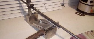
Demagnetization of pipes using pulsed welding current sources is performed in the following sequence.
1- pipe; 2 - welding cable; 3 - DC welding power source; 4 - metal plate; 5 - detachable contact Figure 11.13 - Installation diagram of equipment for demagnetizing pipes using the pulse method
- wind the welding cable (from 18 to 20 turns) at a distance of 10 to 20 mm from the end of the pipe (Figure 11.13), while the ends of the two demagnetized pipes must be at a distance of at least 2500 mm;
- determine the initial value and direction of the magnetic field along the perimeter of the pipe at eight control points;
- set the minimum current on the welding power source (in the range from 30 to 70 A), close the contact to the plate;
- measure the magnitude of the magnetic field along the perimeter of the pipe at eight control points. If the magnitude of the magnetic field has not changed or increased, it is necessary to change the polarity of the current on the solenoid;
- set the maximum current on the welding current source (in the range from 240 to 300 A), close the contact to the plate, hold for 6-12 s, then open the contact and turn off the power source;
- dismantle the demagnetizing windings (solenoid).
Demagnetization of connections before welding with welding current sources using the compensation method is performed in the following sequence:
- determine the initial value and direction of the magnetic field along the perimeter of the welded joint at eight control points;
- wind a welding cable with a cross-section of 35; 50 mm 2 on both ends of the pipes (Figure 11.14), while the winding should be in one direction, uniformly dense and single-row, the number of turns wound on the end of the pipe with a larger magnetic field is from 7 to 11, pipes with a smaller magnetic field fields - from 3 to 5 turns;
- connect the welding cable to a DC power source;
- turn on the welding source and gradually increase the current from the minimum value, while simultaneously monitoring the change in the magnetic field;
- if the magnitude of the magnetic field in the welded joint increases, turn off the power source and change the polarity (change the ends of the welding cable on the power source);
- if the magnitude of the magnetic field in the pipe joint does not exceed 20 Gauss, proceed to welding the root layer of the seam, as the weld is completed, the current value is reduced, while simultaneously controlling the magnitude of the magnetic field in the pipe gap;
- turn off the power source and measure the magnitude of the magnetic field around the perimeter of the joint after welding the root layer of the seam. If the magnetic field value does not exceed 20 Gauss, dismantle the welding cable; if the magnetic field value exceeds 20 Gauss, demagnetize it before welding subsequent layers of the seam.
1- pipe; 2 - welding cable; 3 - DC welding power source Figure 11.14 - Installation diagram of equipment for demagnetizing connections before welding using the compensation method
Demagnetization of connections before welding with welding current sources in an alternating magnetic field using the compensation method is performed in the following sequence:
- determine the initial value and direction of the magnetic field along the perimeter of the welded joint at eight control points;
- carry out demagnetization using a compensation method similar to the requirements of 11.3.3.2 of individual sections of the perimeter of the welded joint with the largest magnitude and one direction of the magnetic field, followed by welding of the root layer of the weld in these sections;
- change the polarity of the current at the power source and demagnetize sections of the perimeter of the welded joint with a different direction of the magnetic field, followed by welding the root layer of the weld in these areas;
- turn off the power source and measure the magnitude of the magnetic field around the perimeter of the joint after welding the root layer of the seam. If the magnetic field value does not exceed 20 Gauss, dismantle the welding cable; if the magnetic field value exceeds 20 Gauss, demagnetize it before welding subsequent layers of the seam.
When may it be necessary to weld a pipe with water?
Unfortunately, even if all the rules described above are observed, welding work may be required on a pipeline that has already been put into operation. Most often this is due to mistakes made by previous welders. Perhaps poor eyesight did not allow the specialist to weld the joint properly, and the area began to leak. If a given pipeline supplies water to a large area that has already been shut off for a long time, then a repeat shutdown could cause a lot of complaints. Therefore, it becomes necessary to perform welding under pressure.
It may also be necessary to weld a pipe with liquid in case of an emergency tap-in, when there is no time to drain the system, and all that can be done is to turn off the pumps to reduce the pressure in the system. Either the area of all communications with water is so large that it will take too long to wait for it to be emptied, or it is too expensive (to drain 20,000 liters of water for one seam). Welded connections of pipelines can be complicated by the presence of liquid in the work area due to the special slope, which is provided for natural gravity flow. In this case, even after draining the system, water will continue to flow and interfere with welding work.
]]>
Demagnetization of main gas pipelines
When welding pipes and other metal products using direct current, so-called “magnetic blowing” is often observed, caused by the residual magnetic field of the pipes. This phenomenon negatively affects the welding process, leading to the formation of weakened areas of the seam, spattering of hot metal, the formation of pores, burns, lack of penetration and other defects. In some cases, ignition of the arc is not possible at all due to sticking of the electrode.
Defects in welds of main gas and oil pipelines caused by high magnetization do not pass technological control. It is necessary to carry out the work again, which leads to loss of time and welding materials.
The magnetization of gas pipelines appears as a result of diagnosing their condition, in which magnetic flaw detectors are used. These non-destructive testing devices are used to detect areas with thin walls and surface irregularities. Additional factors contributing to magnetization are elastic mechanical stresses during the manufacture and transportation of main pipes into the Earth's magnetic field. High-voltage lines located in close proximity to main pipelines can also cause the formation of a magnetic field. The level of residual magnetic field at the ends of the pipes can reach 200 mT.
Since the magnetization of pipes does not allow obtaining good quality welds, demagnetization of pipes before welding is a necessary technological operation. Since it is not possible to completely eliminate the magnetic field, it is allowed to carry out welding at low magnetization levels that do not have a negative impact on the quality of the seam.
Standard STO Gazprom 2-2.2-136-2007 “Instructions on welding technologies for the construction and repair of field and main gas pipelines. Part 1" established the level of residual magnetization of pipe ends and pipeline connecting parts - no more than 2 mT (20 Gauss). When magnetization is more than 2 mT, demagnetization must be performed. The magnetization of the pipe joint for welding work is classified into three levels:
— weak – less than 20 G;
- average - from 20 to 100 Gs;
– high – more than 100 Gs.
To demagnetize a section of a gas pipeline to permissible magnetization limits, it is necessary to create a demagnetizing magnetic field of a greater value than the value of the residual magnetization. To ensure a high-quality weld, the following demagnetization methods are used:
1) The pulse demagnetization method consists of applying one or more magnetic field pulses (1-3 times higher than the initial magnetization level) directed in the opposite direction to the residual magnetic field. As a result, some of the domains are oriented towards the main field and the overall magnetization of the pipe end decreases.
2) Cyclic magnetization reversal. The pipes are demagnetized by an applied alternating field with an amplitude uniformly decreasing from a certain maximum value to zero. The thickness of the demagnetized layer, due to the peculiarities of the penetration of the alternating field, depends on the magnetic properties of the product material and the frequency of demagnetization. The greater the magnetic permeability and thickness of the part, the lower the field frequency should be. Depending on the material of the product, its size and shape, alternating fields of various frequencies are used: from 50 Hz to fractions of a hertz. Thus, the rotation of domains produced by periodic exposure to an alternating magnetic field of decreasing amplitude leads to their disordering and, accordingly, to demagnetization of the product.
3) Compensatory demagnetization method - a constant magnetic field (relatively small) is applied to the pipe, directed towards the vector of residual magnetization. As a result, the applied magnetic field compensates for the residual magnetization and allows for high-quality welding of the seam. As a rule, after welding the root weld, the applied magnetic field is turned off.
Magnetization should be checked using electronic magnetometers at four points across the cross-section of the pipe end.
Features of the Yuvtek Stopmagnit Tube2 demagnetization installation:
— Guaranteed demagnetization with residual magnetization values up to 200 mT;
— The magnitude of the residual field after demagnetization is no more than 1 mT;
— Demagnetization time of one joint (with winding/winding of coils) — no more than 15 minutes;
— Work in automatic, manual and compensation modes;
— Adjustment of output current;
— Changing the polarity and current value in automatic mode;
— Adjustment of current pulse duration;
— Adjustment of the attenuation decrement of the demagnetizing current;
Method of welding magnetized pipelines during repair and restoration work
The invention relates to the field of welding, in particular to welding of magnetized pipelines during repair and restoration work with preliminary demagnetization of welded joints. Before installing a defect-free section, the end zone of the pipeline is demagnetized. The magnetic field is concentrated in a local zone to the value of the residual magnetic field of the pipeline. According to its value, a residual magnetic field is created in the material of the end zone, counteracting the mentioned magnetic field of the pipeline. After this, a defect-free area is introduced and welding is carried out. This makes it possible to improve the quality of welded joints of magnetized pipelines and reduce repair time by eliminating the occurrence of the “magnetic blast” effect in the material. 2 salary f-ly, 6 ill.
The invention relates to the field of electric butt welding and can be used for demagnetization of welded joints of pipelines, incl. and main pipelines.
To assess the technical condition of the linear part of main pipelines and identify defective areas, in-pipe magnetic flaw detectors are widely used, which include rare-earth permanent magnets with high specific magnetic field energy, which leads to the formation of strong residual magnetization in the pipe body of up to 200 mT and above.
When carrying out repair and restoration welding work on hazardous areas identified during the inspection process, the residual magnetic field of the pipeline, acting on the welding arc, disrupts the stability of its combustion and the formation of the weld. This set of phenomena is called the “magnetic blast” effect [1, 2].
There are two widely used methods for demagnetizing parts before welding by:
1) heating parts to a temperature above the Curie point and subsequent cooling;
2) application of an alternating magnetic field with an amplitude gradually decreasing to zero.
Better demagnetization is achieved with the first method. When a body, previously heated to a temperature above the Curie point, is cooled, its domain structure nucleates near the Curie point, and the size of the domains corresponds to the values of the material constants at this temperature. The resulting domain structure does not undergo significant changes when the body cools to room temperature. The constants that determine domain structures with temperature changes change very strongly, so the sample will be demagnetized, but will be in a nonequilibrium state. In addition, when a part is heated to a temperature above the Curie point and subsequent cooling, the mechanical properties of the part material change, which is unacceptable in most cases [3].
Therefore, the method of demagnetizing parts by heating to the Curie point is used in practice extremely rarely.
The second method is to demagnetize the part with an alternating field with an amplitude uniformly decreasing from a certain maximum value to zero. The thickness of the demagnetized layer, due to the peculiarities of the penetration of an alternating field into a conductive medium (surface effect), depends on the magnetic properties of the product material and the frequency of the demagnetizing field. The greater the magnetic permeability and thickness of the part, the lower the frequency of the demagnetizing alternating magnetic field should be. Depending on the material of the product, its size and shape, alternating fields of various frequencies are used: from fractions of hertz (Hz) to 50 Hz. The initial amplitude of the demagnetizing field must be equal to the amplitude of the magnetizing field [3].
Thus, the rotation of domains produced by periodic exposure to an alternating magnetic field of decreasing amplitude leads to their disordering and, accordingly, to demagnetization of the part. When samples are demagnetized by an alternating field of decreasing amplitude, the dimensions of the domains in the demagnetized state depend on the frequency of the demagnetizing field and on the rate of its decrease.
Known demagnetization technologies have been developed and applied to bodies of finite sizes and are practically not applicable when demagnetizing main pipelines - bodies of relatively infinite length [4, 5], due to the constant impact on the demagnetized section of the magnetic fields of adjacent sections of the pipeline.
As a prototype, a method was adopted for welding magnetized main pipelines, including removing the defective zone, installing in its place a defect-free section equal in size, demagnetization of welded joints by reversing the magnetization of the end zone of the joint, and welding of the joints [6].
Demagnetization is carried out symmetrically relative to the cutting zone of the welded seam of the joined pipeline with a defect-free section installed in the seam, which forms two welds. Demagnetization of one of the seams leads to a redistribution of the magnetic field at the other. As a result, simultaneous welding of both seams is practically impossible due to the imbalance of magnetic fields at one of the seams.
Qualified welders can provide high quality welding in a magnetic field of up to 2 mT or less, however, in fields of 2...4 mT the arc becomes unstable, and in fields above 4 mT it becomes highly unstable and is often completely extinguished [3]. The effect of “magnetic blast” during welding works leads to an increase in the time and cost of repairs, a decrease in the quality of the weld and additional financial losses due to an increase in pipeline downtime during repairs. All this requires welding technology to develop technology and means for demagnetizing main pipelines before welding [4].
The basis of the invention is the task of improving the quality of welding of joints of magnetized main pipelines.
The objective is achieved by the fact that in the method of welding magnetized pipelines during repair and restoration work, including removing the defective zone, installing in its place a defect-free section equal in size, demagnetization of welded joints by reversing the magnetization of the end zone of the joint and welding the joints, according to the invention, reversing the magnetization of the end zone material joint zones are carried out before installing a defect-free section and welding until the “magnetic blowing” effect is eliminated in the material, by concentrating the magnetic field in the local zone of the end section of the pipeline to a value equal to the actual value of the residual magnetic field of the pipeline, and according to its value, a residual is created in the material of the end zone a magnetic field opposing said magnetic field of the pipeline, after which a defect-free section is introduced into the joint.
In the welding method, magnetization reversal of the material of the end zone of the joint is carried out along the length of the end zone of the joint in the range (0.15-2.0) of the pipeline diameter.
In the welding method in a magnetized reversal zone, the residual magnetic stray field is redistributed along the generatrix of the cylindrical surface of the pipeline.
For a better understanding of the invention, it is illustrated with drawings, where
Fig.1 - general technological diagram of the claimed method;
Fig.2 - distribution of the magnetic scattering field at the open end of the pipeline in the absence of a magnetized zone;
Fig.3 - distribution of the magnetic scattering field at the open end of the pipeline in the presence of a magnetized zone according to the claimed method;
Fig.4 - known demagnetization scheme before welding;
Fig.5 - known technology for repairing pipelines using a repair reel;
Fig.6 - claimed technology for repairing pipelines using a special tested magnetic field concentrator.
The method of welding a magnetized pipeline 1 is that at the open end 2, zone 3 adjacent to the open end 2 is remagnetized in such a way that the residual magnetic field of zone 3 counteracts the residual magnetic field of pipeline 1, resulting in magnetized pipeline 1 at the open end 2 the value of the total residual magnetic field becomes less than the permissible limits required for high-quality welding and eliminating the effect of “magnetic blowing”, and the length l, experimentally identified, for zone 3 should be no less than (0.15-2.0) diameter d of pipeline 1 ( Fig.1). Depending on the technological conditions of the area and the connection of pipeline 1, the length of zone 3 may exceed (0.15-2.0) the diameter of pipeline 1, but this is not economically feasible. In the remagnetized zone 3, the residual magnetic field B is redistributed along the generatrix of the cylindrical surface of the pipeline (Fig. 3).
In the absence of magnetized zone 3, the magnetic field of pipeline 1 is dissipated at its open end 2 (Fig. 2), where B are the lines of force of the residual magnetic field.
The creation of a magnetized reversal zone 3 of pipeline 1 allows the residual magnetic field to be redistributed and dissipates it not only over a small section of the open end 2, but also over the entire area of the magnetized reversal zone 3. This makes it possible to reduce the magnetization of the open end 2 to the value necessary for high-quality welding (Fig. 3). In known designs [6], demagnetization of the welding zone is carried out either by the compensation method or by the method of pulsed magnetization reversal in a closed magnetic pipeline system (Fig. 4). In this case, the demagnetizing windings 4 are placed symmetrically relative to the cutting zone of the welded seam of the joined pipeline 1. In most cases, repair of pipeline 1 is carried out by cutting out (not shown in the drawing) the defective section of pipeline 1 and installing in its place an equal-sized defect-free section 6, so called a repair coil (Fig. 3), which is equivalent to a closed section of the magnetic circuit.
As a result of introducing a defect-free section 6 into the joint 5, two welds 7 and 8 are formed. The impact of any of the known demagnetization methods on one of, for example, weld 7 inevitably leads to a redistribution of the magnetic field on the other seam 8. As a result, simultaneous welding of seams 7 and 8 becomes impossible due to an imbalance of magnetic fields at one of the seams 7 or 8.
The proposed method (Fig. 6), in which, before installing a defect-free section 6 - a repair coil, magnetization reversal-demagnetization of the material of the end zone 3 of two magnetically unconnected ends 9 and 10 of pipeline 1 is carried out before welding until the effect of “magnetic blowing” is eliminated in the material by concentration magnetic field in the local zone 12 or 13 of the cut ends 9 and 10 of the pipeline 1 to a value equal to the actual value of the residual magnetization field of the pipeline 1, and according to its value, a residual magnetic field is created in the material of the end zone 3 of the ends 9 and 10, counteracting the residual magnetic field of the pipeline 1. The concentration of the magnetic field in the local zone 12 or 13 of the cut ends 9 and 10 of the pipeline 1 is carried out, for example, by a concentrator 14 made of ferromagnetic material, in particular steel 3, which is mated with the gap with the end 9 or 10 of the pipeline 1 in the plane of its outer generatrix . The gap size is set experimentally to be an order of magnitude smaller than the cross-sectional area of the concentrator. The magnetic field concentration is carried out to a value equal to the actual value of the residual magnetization field of the pipeline 1, and according to its value, the zone is demagnetized from the side of the free ends 9 and 10 of the pipeline 1. After that, a defect-free section 6 is introduced between the ends 9 and 10 and welding is carried out. This technology eliminates, during and after demagnetization, the redistribution of the residual magnetic field into magnetically unconnected zones 3 of ends 9 and 10. This allows welding of the seam in the area of ends 9 and 10 and the ends of the defect-free section 6 - the repair coil, eliminating the occurrence of the "effect" magnetic blast" during welding. Thus, the invention improves the quality of welding and reduces the repair time of pipeline 1.
Example. The technological scheme presented below for demagnetization of repaired sections of an oil pipeline concerns the process of demagnetization of pipelines with a diameter of 1400 mm inclusive, during the scheduled repair of defective sections of an oil pipeline.
To carry out the demagnetization process, a set of demagnetization tools was used, consisting of detachable demagnetization windings and an automated magnetic field regulator.
The welding method is carried out using the following technology. After cutting and removing the defective section of pipeline 1, mechanically processing it, preparing the zone for cutting the weld seam on the pipeline and manufacturing a defect-free section - a repair coil, the pipelines are processed, which includes reversing the magnetization of the end zone of the joint until the effect of “magnetic blast” is eliminated in the material by concentrating the residual magnetic field in the local zone of the end section of the pipeline. The concentration of the magnetic field is carried out, for example, by a concentrator made of ferromagnetic material, in particular steel 3. Which is mated with a magnetic gap with the end of the pipeline in the plane of its outer generatrix. The gap size is set to an order of magnitude smaller than the cross-sectional area of the concentrator. The magnetic field concentration is carried out to a value equal to the actual value of the residual magnetization field of the pipeline. Then the end zone material is remagnetized by creating a magnetic field that counteracts the residual magnetic field of the pipeline.
Magnetization reversal of the material of the end zone of the joint is carried out on the experimentally determined length of the end zone of the joint in the range of not less than (0.15-2.0) from the diameter of the pipeline. Outside this interval, towards the minimum of the magnetization reversal effect, the effect of “magnetic blowing” cannot be excluded; towards the upper value of the interval - magnetization reversal is not economically feasible.
In the magnetized reversal zone, the scattering field of the residual magnetic field is redistributed along the generatrix of the cylindrical surface of the pipeline.
After reversing the magnetization of one or both ends of the pipeline, a defect-free section is introduced between them - a repair coil, it is installed and fixed using centralizers on the pipeline, with the required gap, and the root of the weld is welded sequentially, first at one joint between the end of the pipeline and the repair coil, and then in another.
Before welding, detachable demagnetizing windings are mounted on one side and then on the other side at a distance of ~100 mm from the gap. The windings are connected to each other in series and accordingly (the turns of both windings must be wound in the same direction - clockwise or counterclockwise). After this, the windings are connected to an automated magnetic field controller.
The residual magnetic field level indicator, electrically connected to the remote control, is placed in the area of the pipeline end and automatic demagnetization is turned on. After a technologically specified time, the demagnetization process is completed, as indicated by the corresponding indicator, and welding begins. If necessary, an additional cycle of the demagnetizing field level is performed. For this purpose, the demagnetizing windings are shifted with a given step along the pipeline generatrix.
After welding the tacks at the second joint and removing the centralizers from the pipeline, you should begin welding the root of the seam, and then the entire seam.
After welding the entire root of the seam of the second joint, you should disconnect and remove the windings from the pipeline and weld the joints.
Tests carried out under the conditions of repair work on main pipelines showed that the developed technology provides automated, fast, accurate and high-quality demagnetization of the welding zone, is economical and easy to operate, and can be recommended for industrial use when carrying out repairs of pipelines with residual magnetization.
Information sources
1. Blakeley PJ Magnetic Arc Blow: Causes, Effects and Cures//Metal Construction, 1988, Feb.
2. Koster H. Demagnetization of Pipe Ends Before and During Welding//Praktiker, vol. 38, No. 12, 1986, Dec.
3. Prospect.
4. Volokhov S.A. etc. Demagnetization of pipes before welding on main pipelines.// “Non-destructive testing and diagnostics”, abstract. report 15 Russian STC, 1999. - vol. 1, p. 183.
5. Korolkov P.M. Modern methods of demagnetization when welding pipelines // “Welder”, No. 1, 2000, p. 2-4.
6. Prospect KRU "Kharkovneftemash", 1999, p. 1-2.
Claim
1. A method for welding magnetized pipelines during repair and restoration work, including removing the defective zone of the pipeline, installing in its place a defect-free section equal in size, demagnetization of welded joints by reversing the magnetization of the end zone of the joint and welding of the joints, characterized in that the material of the end zone of the joint is reversing is carried out before installing a defect-free section and welding until the “magnetic blowing” effect is eliminated in the material by concentrating the magnetic field in the local zone of the end section of the pipeline to a value equal to the actual value of the residual magnetic field of the pipeline, and according to its value, a residual magnetic field is created in the material of the end zone, counteracting the mentioned pipeline field, after which a defect-free section is introduced into the joint.
2. The method according to claim 1, characterized in that the magnetization reversal of the material of the end zone of the joint is carried out over a length of the end zone of the joint equal to (0.15-2.0) of the diameter of the pipeline.
3. The method according to claim 1 or 2, characterized in that in the magnetized reversal zone the residual magnetic stray field is redistributed along the generatrix of the cylindrical surface of the pipeline.
DRAWINGS
,
,
,
,
,
Demagnetizing pipes before welding on WordPress.com
Welding pipes and steel structures using direct current is often accompanied by the effect of “magnetic blowing,” which is caused by residual magnetization. At the same time, the stability of the process deteriorates, metal spatters, defects such as pores, lack of fusion, lack of penetration, slag inclusions form in the weld, and sometimes welding becomes simply impossible due to arc failure and electrode sticking. The main reason for the magnetization of pipelines is the use of magnetic flaw detectors to diagnose their technical condition, after which the magnitude of the residual magnetic field in the cutting of a welded joint can reach 100-150 mT (1000 - 1500 Gas) or more. Additional factors contributing to the magnetization of pipelines are the Earth's magnetic field, elastic mechanical stresses, and technological magnetization of pipes during their manufacture and transportation.
Since the magnetization of pipes does not allow obtaining a good quality weld, demagnetizing them before welding is a necessary technological operation. It is almost impossible to achieve complete demagnetization, therefore welding is allowed with insignificant residual magnetization, which does not have a noticeable effect on the welding process. For example, the STO Gazprom standard 2-2.2-136-2007 “Instructions on welding technologies for the construction and repair of field and main gas pipelines. Part 1" established that the residual magnetization of the ends of pipes and pipeline connecting parts should be no more than 2 mT (20 G). When magnetization is more than 20 Gauss, demagnetization must be performed.
11.3.3 Demagnetization by welding current sources | Ugra training center
Demagnetization of pipes using pulsed welding current sources is performed in the following sequence:
- wind the welding cable (from 18 to 20 turns) at a distance of 10 to 20 mm from the end of the pipe (Figure 11.13), while the ends of the two demagnetized pipes must be at a distance of at least 2500 mm;
— determine the initial value and direction of the magnetic field along the perimeter of the pipe at eight control points;
— set the minimum current on the welding current source (in the range from 30 to 70 A), close the contact to the plate;
— measure the magnitude of the magnetic field along the perimeter of the pipe at eight control points. If the magnitude of the magnetic field has not changed or increased, it is necessary to change the polarity of the current on the solenoid;
— set the maximum current on the welding current source (in the range from 240 to 300 A), close the contact to the plate, hold for 6-12 s, then open the contact and turn off the power source;
— dismantle the demagnetizing windings (solenoid).
- pipe; 2 - welding cable; 3 - DC welding power source; 4 - metal plate; 5 — detachable contact
Figure 11.13 — Installation diagram of equipment for demagnetizing pipes using the pulse method
Demagnetization of connections before welding with welding current sources using the compensation method is performed in the following sequence:
— determine the initial magnitude and direction of the magnetic field along the perimeter of the welded joint at eight control points;
— wind a welding cable with a cross-section of 35; 50 mm 2 on both ends of the pipes (Figure 11.14), while the winding should be in one direction, uniformly dense and single-row, the number of turns wound on the end of the pipe with a larger magnetic field is from 7 to 11, pipes with a smaller magnetic field fields - from 3 to 5 turns;
Demagnetization by welding current sources
Demagnetization of pipes using pulsed welding current sources is performed in the following sequence:
– wind the welding cable (from 18 to 20 turns) at a distance of 10 to 20 mm from the end of the pipe (Figure 11.13), while the ends of the two demagnetized pipes must be at a distance of at least 2500 mm;
– determine the initial value and direction of the magnetic field along the perimeter of the pipe at eight control points;
– set the minimum current on the welding power source (in the range from 30 to 70 A), close the contact to the plate;
– measure the magnitude of the magnetic field along the perimeter of the pipe at eight control points. If the magnitude of the magnetic field has not changed or increased, it is necessary to change the polarity of the current on the solenoid;
– set the maximum current on the welding power source (in the range from 240 to 300 A), close the contact to the plate, hold for 6-12 s, then open the contact and turn off the power source;
1.7.8 Demagnetization of pipes and joints before welding.
Demagnetization with permanent magnets
Sections of gas pipelines during repair and restoration work (RVR) are subject to demagnetization in cases of the presence of residual magnetism in the metal of the pipes after diagnostics of gas pipelines using in-pipe mobile magnetic flaw detectors, the use of magnetic particle flaw detection of welded joints, as well as the location of gas pipeline sections near power lines, etc.
To reduce the influence of magnetic blast and improve the stability of the arc when welding gas pipelines with residual magnetization, it is necessary:
carry out symmetrical grounding of pipes;
provide each welding station with a separate return cable with a minimum distance between the return cable and the welding point;
place welding cables parallel to the edges being welded;
do not allow the electric holder or bare welding wire to come into contact with the surface of the gas pipeline;
carry out welding in the direction of fastening the return cable; the inclination of the electrode during welding should be in the direction opposite to the deflection of the welding arc.
The magnetization of pipe metal before welding is classified into levels:
weak – less than 20 G;
medium – from 20 to 100 Gs;
high – more than 100 Gs.
To demagnetize a section of a gas pipeline to permissible magnetization limits (no more than 20 Gauss), it is necessary to create a demagnetizing magnetic field with a larger magnetic field and the opposite direction. Complete demagnetization of ferromagnetic steels is impossible.
Demagnetization should be performed using methods
demagnetization:
as well as other methods agreed for use with OAO Gazprom.
The magnetic field strength should be checked using electronic magnetometers.
Demagnetization of connections before welding with permanent magnets must be performed in the following sequence:
determine the initial value and direction of the magnetic field along the perimeter of the welded joint at eight control points;
select permanent magnets taking into account the condition that the magnitude of their magnetic field must be greater than the magnitude of the residual magnetic field of the welded joint. It is allowed to connect magnets in packages (two or more) to increase the magnitude of the magnetic field and the surface of contact with the pipe in order to increase the demagnetizing effect;
install magnets on the area of the welded joint to be demagnetized, in this case, the welded joint should be located between the poles of the magnets, and the poles of the magnets should be opposite to the poles of the magnetized pipes (Figure 14);
use a magnetic field indicator to check the correct installation of the magnets - to change the direction of the magnetic field, you need to rotate the magnets 180 degrees (or swap the poles), to reduce the magnitude of the magnetic field, you need to move the magnets along the surface of the pipes at some distance from the demagnetization point, to increase the magnitude of the magnetic field, the magnets should be brought closer to the demagnetization site;
Figure 14 – Scheme of demagnetization of welded joints
after demagnetization of the welded joint area, the magnitude of the magnetic field should be measured; if it does not exceed 20 Gauss, begin welding the root layer of the weld in this area;
carry out the above operations to demagnetize individual sections of the welded joint, moving permanent magnets and adjusting, if necessary, the magnitude and direction of the magnetic field.
Measure the magnitude of the magnetic field along the perimeter of the joint after welding the root layer of the seam. If the magnitude of the magnetic field does not exceed 20 Gauss, weld subsequent layers of the seam; if the magnitude of the magnetic field exceeds 20 Gauss, carry out demagnetization before welding subsequent layers of the seam.
Adjacent files in item [UNSORT]
Effective ways
Despite the fact that metal objects do not have their own electromagnetic field, it can be extremely difficult to disconnect them from powerful magnets. According to the advice of experts, you can use one of the following methods.
Using a wedge
If you don't know how to remove a neodymium magnet from metal, use a wedge. This can be any non-magnetic tool that is highly durable.
It is not recommended to use various screwdrivers, nails, knives and chisels made of magnetic metal. This can make things very difficult!
Your task is to try to insert an improvised “wedge” between the base and the magnet, and then lift it. This will reduce the force of gravity and it will be easier for you to cope with the task.
Application of a demagnetizer
Industrial demagnetizers reduce the strength of the electromagnetic field and weaken the magnet. They are coils powered by mains power. The exposure time of the demagnetizer depends on the power and size of the magnet. Usually a few minutes are enough to achieve the effect.
Magnet separation “on weight”
If the magnet is stuck to a small metal object, you can try to remove the magnet by weight. To do this, place the object on a table or any other surface made of non-magnetic material. The ideal option is wood. In this case, the magnet should “hang” from the table.
Firmly fix the metal part, and with your free hand pull the magnet down, as if pressing on it. As soon as the magnet begins to give in and slide down, sharply move it away from the object. This will avoid re-sticking.
Magnet shift
If the magnet is stuck to a large, smooth metal surface, such as a door. Don't try to pull it towards you. Also, in this situation, using a “wedge” is not suitable, as the risk of scratching the surface increases. It is best to move the magnet little by little towards the edge, and only then try to remove it.
You can also use special spacers between the magnet or metal. It can be leather or thick fabric. In the future, they will help facilitate the separation process.
If you don't know how to remove a neodymium magnet, use one of the methods listed. Also, observe safety precautions while working. Remember that the high force of attraction makes neodymium magnets unpredictable.
Demagnetization of pipes and sheet steel before welding
Magnetic blast is an undesirable phenomenon when welding steel. Residual magnetization in steel parts can cause instability and deflection of the welding arc. This effect in some cases even forces one to abandon the use of welding.
Workpiece is magnetized - strong arc deflection
Thanks to the use of the Degauss 600 device, materials and parts can be demagnetized. Shortly after simply installing the components on the workpiece, a continuous demagnetization process is automatically carried out.
Demagnetization immediately affects the welding process being performed.
The workpiece was demagnetized using a Degauss 600 - no arc deflection
You will immediately see the result: the welding arc will become stable and will not deviate, there will be no unnecessary ignition points, you will be able to achieve clean border setting without lack of fusion and ideal results without defects and rework.
Your benefits
- Demagnetization of components such as pipes and sheet steel
- One-button control - automatic execution of the demagnetization process
- Stable welding process without arc deflection – perfect results without rework
Demagnetization before welding
Demagnetization during welding
Your benefits – Degauss 600 degausser
- Very simple controls
- All necessary components for demagnetization are included in the kit
- Quick connection to the pipe thanks to three power cables
- One-button control
- Automatic demagnetization process
- Application at temperatures from -25 to +40 °C with mains voltage tolerances +/- 20%
- Portable and reliable
- Very simple controls
How to demagnetize a pipe for welding?
With medium and high residual magnetization of pipes, welding of pipeline joints is accompanied by the appearance of a “magnetic blowing” effect. To neutralize the effect of “magnetic blast,” the welded ends of the pipes are demagnetized.
To demagnetize pipelines under route conditions, devices that compensate for pipeline magnetization (PKNT) have been developed.
Demagnetization with devices that compensate for pipeline magnetization is carried out by compensating the magnetic field of two pipes being welded simultaneously. Demagnetization of joined pipes using PKNT devices is carried out in the following sequence: