Types of incisors
Boring cutters are divided into several subgroups, depending on the main parameters. Feed on the machine can have several directions. Considering this fact, the incisors can be: left; right.
For each type of hole, the required design of the equipment . The accuracy of processing and operation time depend on this. Depending on its design, the tool is divided into several types:
- Direct. The axis of the holder coincides with the line of the cutting head. Sometimes the parallelism of the axes is maintained.
- Bent back. The axis of the tool head can deviate in a certain direction from the axis of the holder.
- Curved. The holder has a curved axis.
- Retracted. The holder is wider than the tool head.
It must be said that sometimes such forms are not enough. Especially when the part has a complex shape. Especially for such cases, designers are developing unique types of boring tools .
The shape of the holder divides the cutters into several types:
- Round.
- Rectangular.
- Square.
The classification of a tool is also influenced by the manufacturing method. The equipment is divided into groups:
- Solid. The tool is made of a homogeneous material.
- Composite. A carbide plate is used to make the cutting part. It can be fixed to the holder with a regular bolt or soldered.
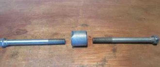
Type 1
Damn.1
Table 1
Dimensions in mm
| Incisors | Plate shape according to GOST 25395-90 | |||||||||
| insert angle 10° | insert angle 0° | Execution | Cutter section | Insertion angle | Diameter of the smallest boring hole | |||||
| Designation | Applicability | Designation | Applicability | 10° | 0° | |||||
| 2140-0056 | 2140-0081 | 2 | 16x12 | 170 | 80 | — | 6,0 | 61 | 40 | |
| 2140-0001 | 2140-0021 | 120 | 25 | 8 | 3,5 | 14 | ||||
| 2140-0002 | 2140-0022 | 1 | 16x16 | 140 | 40 | 01 | 01 | |||
| 2140-0003 | 2140-0023 | 35 | 10 | 4,5 | 18 | |||||
| 2140-0004 | 2140-0024 | 170 | 60 | |||||||
| 2140-0057 | 2140-0082 | 2 | 20x16 | 200 | 100 | — | 8,0 | 02 | 62 | 55 |
| 2140-0005 | 2140-0025 | 20x20 | 140 | 40 | 12 | 5,5 | Insertion angle 10° | Insertion angle 0° | 21 | |
| 2140-0006 | 2140-0026 | 1 | 170 | 70 | ||||||
| 2140-0007 | 2140-0027 | 50 | 14 | 6,0 | 01 | 61 | 27 | |||
| 2140-0008 | 2140-0028 | 200 | 80 | |||||||
| 2140-0058 | 2140-0083 | 2 | 25x20 | 240 | 120 | — | 10,0 | 70 | ||
| 2140-0009 | 2140-0029 | 1 | 25x25 | 200 | 70 | 19 | 8,0 | 34 | ||
| 2140-0010 | 2140-0030 | 240 | 100 | 02 | 62 | |||||
| 2140-0059 | 2140-0084 | 2 | 32x25 | 280 | 160 | — | 12,0 | 80 | ||
| 2140-0060 | 2140-0085 | 40x32 | 300 | 180 | — | 16,0 | 110 | |||
An example of a symbol for a cutter of type 1, version 1, section mm, length mm, with an angle of insertion of the insert into the rod of 10°, with a insert made of hard alloy grade VK4:
Cutter 2140-0001 VK4
GOST 18882-73
Main purpose of the tool
This cutting tool is used in mechanical engineering on a variety of machines: milling; planing; slotting; turning
With the help of this tool, a wide variety of parts are processed with a certain precision. To obtain a product of the desired shape, several layers of metal are removed from the part. To do this, it is firmly fixed in the tool holder.
The working surface of the tool has a very sharp edge, reminiscent of a wedge . It cuts into the workpiece and deforms its outer surface. As a result, it begins to chip. The front surface of the tool shifts it, turning it into chips.
The forward movement continues, the chipping process does not stop, and chip formation continues. Its appearance greatly depends on several factors:
- Part rotation speed.
- Innings.
- coolant
Depending on the type of operation, equipment is divided into several types:
- Turning.
- Slotting.
- Planing.
To move the workpiece together with the tool in the horizontal direction, a planing cutter is installed . If cutting occurs vertically, use a slotting device. Both devices work on the same principle. They differ from similar turning equipment, since on this machine the cutting process occurs continuously. When planing or chiselling is performed, plunging occurs only during the working stroke.
According to the technological process, the processing of a workpiece can have several operations:
- Chernova.
- Semi-finish. The cutter has a cutting plate with a rounded cutting edge. As a result, the surface roughness is improved.
- Finishing.
- Fine turning.
Blind hole machining
Very often there are designs where the parts do not have through holes. To bore them, a special boring cutter for blind holes is used. All types of such instruments are standardized. In GOST you can see the dimensions of the cutter, as well as its design.
When it comes to processing blind holes, a cutting insert in the form of a triangle . For ease of use, the working part of the holder has a slight bend. Based on the diameter of the hole, the corresponding dimensions of the holder are selected.
Boring through holes
To use a curved cutter, a hole is pre-drilled into the part. Its depth is directly dependent on the size of the holder. The longer it is, the greater the depth of the hole. The thickness of the layer of metal removed during this treatment is approximately equal to the amount of bending of the cutting part.
Boring tool for working on a lathe
Turning of parts is considered one of the most important operations in mechanical engineering. Using a boring tool, blind or through holes are processed.
The use of boring tools makes it possible to obtain high processing accuracy and excellent surface roughness. Boring operations are performed only in certain situations:
- When drilling does not provide accurate dimensions and the required surface cleanliness.
- The required tool is not available to obtain the required diameter.
- It is necessary to obtain a straight hole with the exact location of the axis. The diameter of the hole being machined is much larger than the standard drill size.
- Very short hole length.
For processing non-ferrous metals, plastics and other light materials, cutters are used, for the manufacture of which tool steel . If a carbide insert is installed in the work head, durable stainless steel is used.
During operation, the cutting part begins to wear out, and the carbide plate begins to chip. The cutters have to be sharpened .
Boring cutter
The boring cutter can be made in several versions. The high-speed type is used for processing various light materials and corresponding alloys, which include aluminum, fluoroplastic, textolite and other materials.
For stronger and heavier compositions, monolithic, carbide boring cutters or with inserts of carbide alloy plates are used. Such products can already work with bronze, raw steel, stainless steel, hardened steel and other materials.
All these varieties, in turn, are divided by the type of holder, which can be square or round. In addition, there is also a division by purpose. According to the functions performed, a boring cutter for blind holes is produced, which is used not only for processing the internal walls of the hole, but also for grooving the bottom, along with its subsequent grinding. There is also a boring cutter, which is used for through holes. It works with cylindrical parts or those with through holes.
Nowadays, such a variety as a boring cutter with replaceable plates is proving to be very popular. They have different profiles and shapes, and most importantly, they come with a set of spare parts that can be used to fasten working plates and holders. Worn plates can be quickly replaced.
Main Dimensions
Boring tools for lathes, which are designed to work with through and blind holes, are manufactured according to specific size standards.
photo: boring cutter sizes
| Height, mm | Width, mm | Length, mm |
| 16 | 16 | 140 |
| 16 | 16 | 170 |
| 20 | 20 | 140 |
| 20 | 20 | 170 |
| 20 | 20 | 200 |
| 25 | 25 | 200 |
| 25 | 25 | 240 |
| 32 | 25 | 280 |
Geometric parameters of boring cutter
The geometry of the working part of the product consists of three main angles, which in their sum always form 90 degrees. This includes:
- The main clearance angle that is formed between the cutting plane and the flank surface of the tool. It reduces friction between the part and the back surface. The larger this angle, the lower the surface roughness that can be processed. Accordingly, the harder the metal, the smaller this angle should be.
- The point angle, which is measured between the front and back surfaces of the tool. It affects the strength of the product, so the larger it is, the more reliable the boring cutter will be.
- The main front, which is measured between the front surface of the tool and the plane that is perpendicular to the cutting surface. With its help, you can influence the size of the deformation of the removed layer.
photo: geometry of boring cutter
Boring tool selection
The boring cutter is selected according to the materials it will work with. First of all, this is the type for blind or external holes. Next, it is very important to look at the material that is being processed. If the basic geometric principle of a given variety is approximately the same, then the materials used will be different.
“Advice of professionals! Under no circumstances should you use high-speed steel products for processing stainless steel, bronze and hardened metal products. This will lead to rapid wear, so it is better to use only products made of carbide materials here.”
You should also not forget about the size, since some cutters simply physically cannot penetrate the hole. For constant active work, it is advisable to have a set of several products or choose a type with replaceable plates. To process blind holes, specialists select products that are half the diameter of the hole being processed.
Cutting modes with boring cutters
The choice of cutting mode largely depends on the cutter bore, hole diameter, type of material and other factors. Depending on the diameter of the hole being processed, when working with through holes, the cutter must be installed below or above their center. At the same time, when working with blind holes, the internal boring cutter is placed clearly in the center so that there are no bosses at the end.
Marking
There are several main brands of cutters, varying in size and composition. For example, T15K6 - the manufacturing material belongs to the titanium-tungsten carbide group with 15% titanium carbide content and 6% cobalt content.
Fastening the cutting elements of the cutter
The machine has a special tool holder. Several different cutters can be mounted in it at the same time. The cutter is fixed with special bolts. The tool must be positioned parallel to the centering axis of the machine. The cutting head of the tool must face the spindle.
The turner, installing the cutter, sets its tip . It must coincide with the center axis of the machine (slightly above the center is allowed). If you set the tip below the centerline, the back of the tool will hit the workpiece.
To control accuracy, the cutter is brought directly to the top of any headstock. Adjustment is carried out using pads of different thicknesses . And there should only be two of them. Otherwise, the tool will begin to vibrate.
The protrusion of the cutter from the tool holder should be minimal . If the overhang is too large, the strength of the cutter will become much less. Vibration may occur during boring. The mounting of the cutter must be very reliable. Definitely two bolts.
Type 2
Damn.2
table 2
Dimensions in mm
| Designation of cutters | Applicability | Execution | Cutter section | Type of plates according to GOST 25395-90 | Diameter of the smallest boring hole | |||
| 2140-0071 | 2 | 16x12 | 170 | 18 | — | 6,0 | 61 | 40 |
| 2140-0251 | 120 | 25 | 8 | 3,5 | 14 | |||
| 2140-0252 | 1 | 16x16 | 140 | 40 | 01 | |||
| 2140-0041 | 35 | 10 | 4,5 | 18 | ||||
| 2140-0042 | 170 | 60 | ||||||
| 2140-0072 | 2 | 20x16 | 200 | 20 | — | 8,0 | 62 | 55 |
| 2140-0043 | 140 | 40 | 12 | 5,5 | 21 | |||
| 2140-0044 | 1 | 20x20 | 170 | 70 | 61 | |||
| 2140-0045 | 50 | 14 | 6,0 | 27 | ||||
| 2140-0046 | 200 | 80 | ||||||
| 2140-0073 | 2 | 25x20 | 240 | 25 | — | 10,0 | 70 | |
| 2140-0047 | 1 | 25x25 | 200 | 70 | 19 | 8,0 | 34 | |
| 2140-0048 | 240 | 100 | 62 | |||||
| 2140-0074 | 2 | 32x25 | 280 | 30 | — | 12,0 | 80 | |
| 2140-0075 | 40x32 | 300 | 40 | — | 16,0 | 110 |
An example of a symbol for a cutter of type 2, version 1, cross-section mm, mm, with a plate made of hard alloy grade VK6:
Cutter 2140-0042 VK6
GOST 18882-73
(Changed edition, Amendment No. 2).
4. For type 1 cutters, the angle of insertion of the plate into the rod for processing cast iron and other brittle materials is 10°, for processing steel and other viscous materials - 0°.
(Changed edition, Amendment No. 1).
5. The values of radii of roundings and chamfers not specified in this standard are accepted for technological reasons.
6. Structural elements and geometric parameters of the cutters are indicated in the appendix.
7. The form of sharpening the front surface and finishing of the cutting part are specified in Appendix 2 to GOST 18877-73.
8. Technical requirements - according to GOST 5688-61.
9. (Deleted, Amendment No. 2).
APPENDIX Recommended
STRUCTURE ELEMENTS AND GEOMETRICAL PARAMETERS OF CUTTERS
1. Structural elements and geometric parameters of the cutters are indicated in Figures 1-6 and Tables 1-4.
Type 1
Damn.1
Damn.2
Table 1
Dimensions in mm
| Designation of plates according to GOST 25395-90 | ||||||||||||
| Cutter section | Insertion angle | Insertion angle | ||||||||||
| 10° | 0° | 10° | 0° | 10° | 0° | |||||||
| 15 | 9,5 | 8 | 3,4 | — | 6,4 | 4 | ||||||
| 16x16 | 30 | 3,8 | 4,4 | 01331 | ||||||||
| 23 | 12,0 | 8 | 5,0 | — | 8,0 | 5 | ||||||
| 48 | ||||||||||||
| 26 | 15,0 | 10 | 4,5 | 5,2 | 5,4 | 5,6 | — | 9,6 | 6 | 01351 | 61351 | |
| 20x20 | 56 | |||||||||||
| 34 | 17,0 | 12 | 6,2 | 7,1 | 6,0 | 6,2 | 8,7 | 11,2 | 7 | 01371 | 61371 | |
| 64 | ||||||||||||
| 25x25 | 49 | 24,0 | 14 | 9,7 | 10,9 | 9,0 | 9,2 | 12,2 | 15,2 | 9 | 02251 | 62251 |
| 79 | ||||||||||||
Damn.3
Crap. 4
table 2
Dimensions in mm
| Designation of plates according to GOST 25395-90 | ||||||||||||
| Cutter section | Insertion angle | Insert angle | Insertion angle | |||||||||
| 10° | 0° | 10° | 0° | 10° | 0° | 10° | 0° | 10° | 0° | |||
| 16x12 | 12 | 6,2 | 7,1 | 10,8 | 11,0 | 13,5 | 10 | 10 | 10 | 01372 | 61372 | |
| 20x16 | 14 | 9,7 | 10,9 | 13,8 | 14,0 | 17,0 | 12 | 14 | 13 | 02252 | 62252 | |
| 25x20 | 18 | 13,7 | 14,9 | 18,8 | 19,0 | 22,0 | 16 | 19 | 18 | 02272 | 62272 | |
| 32x25 | 22 | 15,3 | 16,7 | 24,7 | 25,0 | 28,5 | 20 | 21 | 20 | 02312 | 62312 | |
| 40x32 | 25 | 16,4 | 18,2 | 29,6 | 30,0 | 34,8 | 35,0 | 28 | 22 | 21 | 02352 | 62352 |