Dynamic machines often experience short-term, higher-than-peak loads. In most cases, they are caused by malfunctions of certain equipment systems. Changing the design of a machine is an expensive task. This procedure will increase the size of the device and complicate its maintenance. From an economic point of view, it is more profitable to create a power circuit based on rated loads and connect a protective device to the equipment. A slip clutch is one such option.
Article navigation
Features and application of safety couplings
Types of safety couplings
Friction
Spring-cam
Features of the operation of a spring-cam device
Features and application of safety couplings
Safety or overload clutches are used to transmit torque, which is why they are sometimes called torque limiting clutches. Areas of application of protective devices:
- equipment, impact technology;
- mechanisms used to work with heterogeneous environments;
- automated equipment;
- kinematic schemes that transmit a small part of the power of the drive motor.
Safety products are combined with compensating models for working with misaligned shafts.
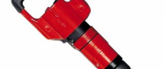
Disassembling the hammer drill
The case of most devices is made of two halves: rear and front. They are tightened together using screws located parallel to the direction of the drill installation axis. But it happens that the halves are attached using side fastenings. Before unscrewing the fastening element connecting the halves of the housing, you will need to remove the cartridge.
The cartridge used corresponds to the SDS-plus or SDS-Max standard. To disassemble it you will need a flat-head screwdriver. At the first stage, the chuck clamp is released from the installed drill. If the mechanism itself is jammed and cannot be untwisted, then you should tap it in a circle with gentle blows of a rubberized hammer. It would not hurt to apply flushing fluid. At the next stage, the plastic casing is pulled down and the rubber boot is removed with a screwdriver. After this, all that remains is to remove the retaining ring, using a screwdriver, and remove the spring with the ball and the retaining plates.
When the cartridge is removed, the housing parts are removed. When disassembling the tool, you should be careful, remembering the order in which the elements are removed and their location. If there is a cover on the handle, you should remove it too. After that, all that remains is to carefully separate the housing and gearbox in different directions. Using the resulting gap, the switch button is removed. The brush holder is removed.
The button for setting operating modes, despite the types of devices, is removed in the same way. The switch is set to the strike position (shown on the body as a hammer), after which it is slightly pryed and turned counterclockwise one or two centimeters. Then, the switching pad is removed by pulling it towards you and the seat is freed up.
Friction
Safety clutches for gearboxes of this type are considered the simplest. They are suitable for short-term impact overloads. They are used in combination with flanges, sprockets, and pulleys. At normal force, the device transmits the load by compressing the flanges and the hub. If the force indicators exceed the permissible values, the flange will rotate along the bushing. The permissible level of torque depends on the location and number of springs. Design of safety couplings:
- hubs;
- friction linings;
- bushings;
- locking screws;
- movable pressure disk;
- disc springs;
- rotation sensors (not included in the standard delivery package).
The rotary sensor allows you to adjust the slipping time of the connection. This will minimize damage. Sliding ends automatically, but the mechanism continues to operate. The hub is often replaced with a needle bearing. This modification is necessary if the sliding speed and radial loads are high and the requirements for the location of the shaft and drive are very strict. The torque range of modern safety connecting elements is from 2 to 50,000 Nm, and the shaft diameter is up to 200. The slipping speed decreases with increasing size of the protective device.
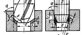
23, a. Designation of mounting holes for couplings with straight-sided splines according to GOST 1139-80
Dimensions, mm
| D | Designation according to GOST 1139-80 | D | Designation according to GOST 1139-80 | ||
| z×d×D | b | z×d×D | b | ||
| 14 | 6×11×14 | 3,0 | 28 | 6×23×28 | 6,0 |
| 16 | 6×13×16 | 3,5 | 32 | 6×26×32 | 6,0 |
| 20 | 6×16×20 | 4,0 | 38 | 6×32×38 | 6,0 |
| 22 | 6×18×22 | 5,0 | 42 | 6×36×42 | 7,0 |
| 25 | 6×21×25 | 5,0 | 48 | 6×42×48 | 8,0 |
Spring-cam
This type of safety clutch is characterized by high operating accuracy. The main role in increased accuracy is given to the elastic properties of the spring. When peak torque is reached, the spring-cam mechanism is more likely to operate than the friction mechanism. The advantages of the product include high torsional rigidity and no backlash. This is especially important when operating servo drives. Spring-cam safety clutches also have disadvantages. They are very limited in speed characteristics. At high speeds, the protective elements are overloaded many times due to self-switching. Over time, the torque indicator drops. Spring-cam mechanisms are:
- cam;
- cam-roller;
- ball.
Cam clutches are the most difficult to manufacture, so manufacturers often use ball products. With this design, sliding friction is partially replaced by rolling friction. Cam-roller models have radially arranged rollers. During operation, the balls are pressed against the sockets due to the transfer of force from the plates. If the load is higher than the rated load, the ball flies out of the socket and the force is transferred.
How a screwdriver works and the design of the tool - what you need to know when using it
The output voltage of the battery determines the power of the device.
Most often, screwdrivers use lithium-ion voltage 3.6 V and nickel-metal hydride, nickel-cadmium 1.2 V elements. The output voltage of different batteries can be within 3.V, but the most applicable range is 9.4V. An important indicator of a battery power source is the capacity, which is responsible for the service life. This characteristic is usually within 1.5 Ah. The tool is turned on by pressing the screwdriver button located on its handle.
This push-button switch is combined with a voltage regulator - with different pressing forces, a different voltage value is supplied to the electric motor, which is provided by a wide-pulse regulator. The rotation direction lever is also located in the button installation area. This switch allows you to change the polarity of the supplied signal, which provides reverse rotation.
The electric motor is started through a fairly powerful transistor, the opening process of which is controlled by a PWM generator. The electrical signal is supplied directly to the engine rotor through the commutator. Search titles only User posts: Separate participant names with a comma.
Features of the operation of a spring-cam device
The protective element provides the following methods for restoring shafts:
- Automatic when overload stops. The rotation continues.
- Manually or using a special mechanism. This method is used if an additional locking mechanism has been installed. It is mounted between the movable disk and the spring block.
- Continuous transmission of rotation. It is activated when the mechanism cannot be stopped. The equipment is additionally equipped with a disc stroke limiter and an alarm. In a critical situation, the disk moves all the way and activates the alarm.
The use of spring-claw couplings helps reduce the cost and size of machines. Operating costs are also reduced, because equipment reliability increases.
Historical creation
It should be noted that the viscous coupling invention is far from new. This principle was known back in 1917 in the USA. It was there that its creator, the talented engineer Melvin Severn, lived. Unfortunately, in those days the principle of fluid viscosity in the transmission was not appreciated, and there was no particular need for it. The viscous coupling would have sunk into oblivion, but unexpectedly in 1964 it reappeared in the world automotive arena in the transmission of the British sports car Jensen Interceptor FF. This was the debut of the viscous coupling in a production car and since then it has been actively used and used by various automakers.
Delivery contents
Typically, a basic mechanical drive industrial dog clutch package includes two coupling halves, a ring gear assembly, packaging and documentation.
Often in shipping documents, coupling halves are called hubs.
A set screw is available as an additional option to facilitate installation of the device on equipment. If the dog clutch is equipped with an electromagnetic or hydraulic drive, a wiring diagram is added to connect to the hydraulics or electrical circuit of the unit.
At the manufacturer's factory, the coupling is assembled and tested on a test bench, and a note is made about the results in the product's shipping passport.
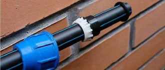
Types of fittings
In addition to the materials of manufacture, couplings differ in their technical characteristics, but the main difference is the installation method. According to this indicator they are:
- compression;
- crimping;
- welded plastic;
- threaded
Let's look at each of these types in more detail.
Compression coupling. Ease of use is the main advantage of such a detail. It is fixed by pressing a special ferrule into the ferrule. This technical solution eliminates the possibility of unwinding during vibrations of various types, as well as water hammer. The advantages include:
- versatility;
- ease of installation with your own hands. Installation work can be carried out by a person with only basic plumbing skills;
- possibility of repeated use;
- no need to use a welding machine;
- low cost.
A compression coupling is a simple design in which the seal is ensured by O-rings and nuts
Installation is carried out as follows:
- parts of the fastening element - collet ring, nut, etc. – put on the pipe;
- then the pipe is pushed onto the fitting or inserted into the pipe of the connecting component;
- then the collet ring is pushed on and the nut is tightened.
Crimp coupling. The scope of application of such a product is metal-plastic water supply systems. It should be noted that the need for a crimp coupling arises infrequently. This is due to the fact that the sale of “metal-plastic” is carried out in multi-meter coils. When the crimping part is still needed, install it in the following order:
- cut the edges of the tubes at right angles;
- insert the tubes into the sleeves;
- Crimp the connection point with a special tool.
Welded plastic coupling. The type of plastic makes a difference in the plumbing assembly process. Briefly they are formulated as follows:
- HDPE. Installation of HDPE water supply, as a rule, is carried out using an electric welded coupling with electric spirals. Having joined all the parts, connect a special device to this type of coupling. After turning it on, electric current will begin to flow into the coil, causing it to heat up to the melting point of polyethylene. As a result, the material of the components is mixed, and after cooling, a very strong connection is formed.
- PVC. The installation method of such a pipeline is more similar to gluing rather than welding. And here the surfaces being connected melt, but not due to high temperature, but under the influence of a special chemical composition - glue. However, this method is usually called sleeve welding.
PVC pipes can be connected using the adhesive method, but in this case the coupling is still called welded
Installation involves the following sequence of actions:
- cut the pipe to be connected and insert it into the connecting piece;
- Place a mark on the surface of the pipe indicating the insertion depth;
- Coat the marked area with a brush with a thin layer of the above glue;
- connect the elements. Having done this, be sure to turn them a quarter turn;
- Glue the second pipe a few minutes later in the same way.
Polypropylene. Welding a fitting looks like this:
- the connecting piece and pipe are inserted into preheated nozzles of a special soldering iron;
- after the plastic surfaces have softened, remove the parts from the soldering iron and connect them to each other;
- After letting the plastic cool, connect the second pipe to the fitting in the same way.
Threaded coupling. Such fittings are usually used for steel pipelines. Instructions for installing a threaded coupling are presented below.
- cut the pipes to be connected strictly perpendicular to the longitudinal axis;
- cut threads on them;
- then screw on the tightening nuts;
- then screw the pipes into the connecting piece one by one.
Threaded couplings of various types are used when installing metal pipelines
Examples of using
Socket wrenches and screwdrivers
Socket wrenches equipped with a ratcheting mechanism are also called ratchets. In the simplest version of the design, two pawls are placed in the ratchet. By turning the lever, you can either unscrew the nut or tighten it without removing the key at each turn, as with a conventional tool.
Ratcheting socket wrenches
Cable ties
Cable ties are made of plastic in one piece. The pawl is pressed against the toothed plate by elastic force. After tightening, the tie does not loosen even with very great force.
Ratchet Cable Tie
Recoil devices
Ratchet recoil devices were originally used on railroads in the mountains of Pennsylvania, USA, to transport coal around 1846. To prevent a loaded train from rolling back down a steep slope in the event of a locomotive engine failure, “dogs” were installed on the cars.
Later, this scheme was used on roller coasters, so that in the event of a power outage, the train with thrill-seekers would not roll back.
Roller coaster trolley recoil device
Winches
Winches are a mechanism for moving objects using a rope. An electric winch is installed in SUVs to pull a stuck car out of a quagmire.
To prevent the tensioned cable from unwinding from the drum, a ratchet mechanism is used. Examples of its use on hand winches can be seen in these photographs.
Ratchet mechanism in hand winches
Bicycle freewheel
An overrunning clutch is also called a freewheel. It prevents the transfer of torque from the driven shaft (wheel) to the drive shaft (chain and pedals) if the driven shaft begins to rotate faster. For example, after stopping pedaling without a freewheel, the wheels would continue to spin the chain and pedals, as was the case in the first bicycles. The same would happen when going down a hill.
The first overrunning clutch with a simple ratcheting mechanism was patented in 1869 by William Van Anden from Poughkeepsie, New York, USA. The Van Anden overrunning clutch had a ratchet built into the front wheel hub of the bicycle.
Approximate diagram of a freewheel (overrunning clutch) with a Van Anden ratchet mechanism
Almost all modern bicycles are rear-wheel drive. The overrunning clutch is built into the rear hub or rear sprocket. Overrunning clutches with a ratcheting mechanism produce a characteristic sound and are also called bicycle ratchets.
An example of how a freewheel works. A freewheel with a ratcheting mechanism in the rear sprocket of a bicycle.
Car starter overrunning clutch
The ratchet freewheel mechanism is used in automobile starters as a safety device. A starter is a mechanism that, using an electric motor, starts an internal combustion engine by rotating its crankshaft through the flywheel.
The rotation speed of the starter driven gear is low - maybe about 3000 rpm. After starting, the engine idles at about 1000 rpm. But the starter-flywheel gear ratio can reach 20:1 due to the difference in gear diameters. Those. a running engine at idle speed can spin the starter motor up to 20,000 rpm.
To prevent the starter from failing after starting the engine, a freewheel is installed on it.
Car starter
Car gearbox
In this example, the ratchet pawl is used to place the automatic transmission into park.
Ratchet in a car's automatic transmission
Main types of shaft misalignment
One of the main factors for using couplings is their ability to compensate for errors in the relative position of the shafts. Understanding the type of misalignment is sometimes critical when selecting the correct coupling.
When installing equipment, the shafts must be positioned without any displacement, which is often unattainable. A discrepancy or deviation between the intended position of two shafts is usually the result of manufacturing tolerances. Misalignments can be radial (longitudinal), angular and axial.
Correct shaft placement
Radial (longitudinal) shaft displacement
Axial displacement of shafts
Shaft angular displacement
Types of Shaft Misalignment