The production of modern equipment places high demands on the manufacture of parts and the quality of mating surfaces. To implement technological tasks when processing on a machine, a specialized tool is used. A counterbore is a cutting tool for performing secondary machining of holes in parts for various purposes.
The counterbore operation allows you to form a support or contact area with high quality and accuracy for the subsequent installation of fasteners such as bolts, nuts, washers or support rings.
Area of application of the tool
Counters are a multi-edge tool and are a type of countersink. They are used when performing technological operations to create a cylindrical or conical surface. Face countersinking is used to level the support areas near the finished hole. The resulting recesses allow you to place the heads of the fasteners so that they do not protrude above the surface.
The following types of machining are carried out using the counterbore process:
Countering
- Alignment of ends in internal structural elements;
- Supporting surfaces for fasteners are made;
- Burrs and sagging are removed;
- Stepped holes are created;
- Chamfering edges.
The cutting tool allows you to work on the machine with steel, cast iron workpieces and parts made of non-ferrous metal and various alloys.
Countering holes is aimed at solving important technological problems:
- Increased quality of processing of internal elements.
- Preparation for subsequent processing and assembly operations.
- Implementation of standards for geometric accuracy and location, for example, normal location to the axis of the machined hole.
Due to the similarity of design and technology of use, the counterbore was called an end countersink.
The tool is used on drilling, turning, milling, boring and specialized metal-cutting machines.
A variety of counterbores for processing hard-to-reach areas include reverse tools. The counterbore is mounted on a mandrel and trims the end by moving the quill from bottom to top, and not vice versa, as in traditional machining on a machine.
Work performed on a drilling machine
9.10. Sequence of reading a general view drawing
- Using the data contained in the title block and the description of the product’s operation, find out the name, purpose and operating principle of the assembly unit.
- Based on the specification, determine which assembly units, original and standard products the proposed product consists of. Find in the drawing the number of parts indicated in the specification.
- Based on the drawing, represent the geometric shape, the relative position of the parts, how they are connected and the possibility of relative movement, that is, how the product works. To do this, it is necessary to consider in the drawing of the general view of the assembly unit all the images of this part: additional views, sections, sections, and extensions.
- Determine the sequence of assembly and disassembly of the product.
When reading a general view drawing, it is necessary to take into account some simplifications and conventional images in the drawings, allowed by GOST 2.109-73 and GOST 2.305-68*: On the general view drawing it is allowed not to show:
- chamfers, roundings, grooves, recesses, protrusions and other small elements (Figure 9.21);
- gaps between the rod and the hole (Figure 9.21);
- covers, shields, casings, partitions, etc. in this case, an appropriate inscription is made above the image, for example: “The cover pos. 3 is not shown”;
- inscriptions on plates, scales, etc. depict only the contours of these parts;
- in a cross-section of an assembly unit, different metal parts have opposite hatching directions, or different hatching densities (Figure 9.21). It must be remembered that for the same part, the density and direction of all hatchings are the same in all projections;
- the sections show, not dissected: the component parts of the product for which independent assembly drawings are drawn up;
- such parts as axles, shafts, fingers, bolts, screws, studs, rivets, handles, as well as balls, keys, washers, nuts (Figure 9.21);
Assembly drawings contain reference, installation, and as-built dimensions. Executive dimensions are dimensions for those elements that appear during the assembly process (for example, pin holes). Figure 9.21 - Assembly drawing Figure 9.22 - Specification
Description of the design and modification of the tool
The counterbore is considered an axial cutting tool. On one side of the cylindrical body there is a working area with several blades, and on the opposite side there is a shank for mounting in the machine chuck. A special feature of the tool is the location of the working processing edges in the end part. Helical grooves run along the side surface to remove chips from the processing zone.
Counterbore with replaceable pin, diameter 12 mm
Perpedicularity and positioning accuracy during the processing of end surfaces is ensured by a special journal in the cutting zone of the tool.
During the cutting process, the guide pin enters the hole and is tightly fixed in it, ensuring the correct, coaxial position of the tool.
Installation and fixation of the counterbore on the machine is carried out, as with all axial tools, by means of a shank.
Types of counterbores
Countersinks for metal-cutting machines are divided into two large groups: cylindrical and conical.
Countering according to GOST
For conical countersinks, the working head profile angle is 60°, 75°, 90° and 120°. The number of cutting edges depends on the diameter. Counters can be with a cylindrical or conical shank. The conical tool is intended for finishing fasteners and for chamfering. The production of conical countersinks is regulated by GOST 14953-80.
Cylindrical countersinks come with a cylindrical and conical shank. An option is available with a wear-resistant coating of rubbing areas. The intended purpose of such a tool is to process support areas.
In accordance with the standards of GOST 26258-87, which regulates the technology for manufacturing counterbores, cylindrical counterbore tools are divided into the following categories:
- With solid guide pin and cylindrical shank shape.
- With replaceable trunnion and conical shank.
- Mounted design, when the blade head is mounted on a mandrel. The guide pin is replaceable and is also fixed to the mandrel.
- With change of shank and axle. Installation on the machine is carried out using a pin lock.
Types of counterbores
Materials and working attachments
The working area of all mounted bores can be made solid from high-speed steel or with brazed plates made of carbide. Cutting tools with a cylindrical attachment point are made only from quick cutters.
Counterbodies with built-in carbide plates
Counterbodies, with built-in hard alloy plates, allow processing of cast iron of various grades and structural steels. Quick cutter tools only work with steels.
The number of blades on the counterbores depends on the design. A solid tool with a cylindrical end has 2-4 cutting edges. Tools in other categories only have 4 blades.
The method of securing the tool in the machine is influenced by the design of the shank. The counterbore with a cylindrical edge is installed directly into the machine chuck. The tool with a cone is mounted in a mounting hole with a special Morse taper. Installing a counterbore with a pin-type locking mechanism requires a pin lock on the machine.
Design features
The counterbore is an axial-type metalworking device. It includes three components:
- Working part. At the end of the tool there is a contact area with cutting blades for processing the metal surface. It also includes a guide pin.
- Tail part. It is located on the opposite side and is fixed in the machine chuck.
- Connecting part. Located between the above elements. Its purpose is to transmit torque from the machine to the cutting edges.
The counterbore can be a monolithic device or a prefabricated structure, depending on the type of execution.
A special feature of the tool is the end arrangement of the blades.
During the work process, the mechanism for removing removed metal shavings is very important. In counterbores, this function is performed by screw channels located in the side of the device.
The guide pin is responsible for the quality of processing and the angle of inclination of the counterbore during the work process. This is achieved by securely fixing the trunnion after the tool is immersed in the hole. Thus, work is carried out in a given plane, without axial displacement.
The process of installing a counterbore is no different from the operation of other axial-type devices: the shank is clamped by the machine chuck.
Tool material
Structural steel grades 45, 40X and 45X are used for the base counterbore rod. The cutting zone can be manufactured from the following materials:
Rod length
- The monolithic cutting area is made of high-speed alloy that meets the recommendations of GOST 19265.
- The material for carbide cutting inserts is selected from alloy VK8, VK6, VK6M, T15K6, T5K10.
- The properties of the material and the requirements for it are set out in GOST 3882. Compliance with geometry and dimensional parameters is controlled by GOST 25400.
Carbide plates are attached to the holder using solder MNMts 68-4-2, brass type L63 and L68. The solder thickness must be no less than 0.2 mm.
Wood, plastic and soft metals are processed with countersinks made of tool steel. Carbide countersinks have high durability and can withstand significant cutting forces that arise when machining strong steel parts on a machine.
The hardness of the cutting surface of countersinks made of tool steel is not lower than 62..66 HRC, the hardness of the shank is 36...45 HRC. The hardness on the body along the entire length of the countersink with carbide inserts is 35…46 HRC.
Scheme of the cutting surface of countersinks
Types of metal galvanizing
In the modern world, galvanizing is used to treat metal surfaces. It serves primarily to protect against corrosion. Different metals require different methods of this process. This is due to the fact that not all metals are able to adhere to zinc under certain conditions.
The main methods of galvanizing metal are presented in the following ways:
Cold galvanizing of metal
This method differs from all others in that it does not require a special bath. The zinc alloy solution is applied in the same way as any paint coating.
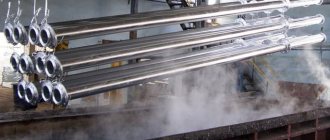
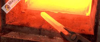
Hot galvanizing of metal
This procedure involves lowering a metal product into a bath of zinc alloy for processing. The galvanizing process occurs under the influence of slight heating. This allows the solution to be applied to the surface more evenly.
Galvanic galvanizing of metal
This method is characterized by the fact that the entire procedure occurs under the influence of electric current. Metal is dropped into the electrolyte solution and an electric current is connected, supplying a small voltage.
Thermal diffusion galvanizing of metal
It consists of applying a zinc alloy of any thickness to the metal surface. It is determined by the customer. Special containers are used for the procedure.
Table 1. Comparison of zinc with other metals.
Name of the metal Brief description Property of the metal Application Aluminum is a silver-white metal Melting point 650°C. Aluminum is resistant to atmospheric corrosion due to the formation of a dense oxide film on its surface
The most important feature of aluminum is its low density - 2.7 g/cm3 versus 7.8 g/cm3 for iron and 8.94 g/cm3 for copper. Has good thermal and electrical conductivity
Handles well under pressure. It is used in the electrical industry for the manufacture of current conductors, in the food and chemical industries. It is used as a deoxidizer in steel production, for aluminizing parts to increase their heat resistance. It is rarely used in its pure form due to its low strength - 50 MPa. Chrome is a shiny non-ferrous metal with a bluish tint, with a specific gravity close to iron. It is quite hard (one less than diamond), however, fragile. It is quite hard, but nevertheless fragile. Melting point 1910 °C. Resistant to oxidation in atmosphere and water. Nitric acid does not dissolve it. It dissolves gradually in solutions of hydrochloric and sulfuric acids, but more actively in strong hydrochloric acid. Chrome is quite strong against abrasion. In its pure form, chromium is widely used for decorative and anti-corrosion coating of other metals. In industry, chromium is widely used for the production of high-strength alloyed chromium steels. Copper is a red metal, pink when broken, has high ductility and corrosion resistance, high electrical and thermal conductivity (100% pure copper is the standard, then 65% aluminum, 17% iron), as well as resistance to atmospheric corrosion. Allows you to use it as a roofing material. material for critical buildings Titan (Te) is a light metal of silver-white color. has a high melting point, low thermal conductivity and poor anti-friction properties, but is easily forged and stamped. When heated to 500 °C in air, it does not oxidize, and at higher temperatures a strong protective film forms on its surface. Therefore, titanium and its alloys are used to make the skin of supersonic aircraft, jet engine compressors, in a turbo structure - shovels and turbine disks, etc. From sheet titanium it is possible to make (using argon welding) lightweight mufflers for cars that do not rust or burn out.
Production requirements
The technology for producing counterbores is brought into compliance with the provisions of GOST 26258-87. According to the requirements, tools with a working area diameter not exceeding 8 mm, and a cylindrical tail part, as well as an attachment structure, are manufactured solid. Counters with an outer size of 8 mm, regardless of the type of shank, are welded. The working head and the clamping part in this case are made of different grades of steel.
Cylindrical counterbores for processing supporting surfaces for fasteners according to GOST 26258-87
Increased demands are placed on the quality of the connecting seam during welding. The presence of voids, cracks, oxides, porosity and burns is unacceptable.
Defects in the form of oxides, cracks and nicks are excluded on the edges. The sanded areas should not contain damage or tears, chips or burns.
Geometry control involves checking for reverse taper in the tool when the diameter decreases towards the tail. The counterbore must have a uniform diameter along the entire length of the cutting part of a high-speed tool. The permissible deviation is less than 0.08-0.16 mm per 100 mm of length. There should also be the same size in height of the plates on the counterbore with brazed plates, the tolerance for which is 0.05-0.1 mm per plate size.
Getting holes
In order to thoroughly understand what countersinking is, you need to have an idea of how holes are made in parts. Let's say it is necessary to drill a hole of the fifth accuracy class with a diameter of 12 mm in a workpiece. An important indicator that affects the maximum and minimum values is the required quality. For example, it is necessary to finish countersinking a hole with a diameter of 85 mm with grade H11. Based on the tables of tolerance fields for holes with nominal sizes from 1 to 500 mm, for quality 11 (for diameters from 80 mm to 120 mm) the tolerance field is: the upper value is “+220”, and the lower value is “0”, that is, 85 +220 mm. The maximum diameter of the drilled hole cannot exceed 85.22 mm, and the minimum - 85 mm.
In this case, the size tolerance is the difference between D max and D min, that is, it will be 0.22 mm. If we talk about defects, then for a hole a diameter above the value of 85.22 mm will be considered irreparable, and a diameter less than 85 mm will be considered reparable.
A countersink is a metal-cutting tool with several working blades, designed for processing pre-drilled holes of cylindrical or conical shape. Using a countersink, when choosing the required type of tool, you can obtain recesses of different configurations in the holes of the workpieces. Countersinking should not be confused with countersinking, drilling holes to their full length to improve the quality of the surface.
Recommendations for counterweighting
Using a combination tool will help increase productivity when making holes on a machine. This type of tool allows you to perform several operations from one installation, for example, drilling, reaming a hole and chamfering.
Methods for restoring parts
The counterbore process on the machine is carried out with cutting modes similar to those for countersinking, and with a small working stroke.
It is convenient to process elements of the same type in an open area against a stop. The guide part can only come into contact with the surface of the hole with screw strips. Otherwise, the tool may jam in the hole as a result of overheating and thermal expansion.
Counterbore holes are often used in machining in industrial production and repair shop settings. In any application, counterbore fulfills all the requirements for the manufacture of a part and improves the performance characteristics of machine mechanisms.
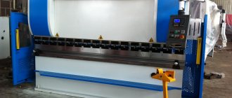
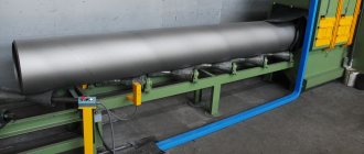
Scraper conveyors TSC 50 tons per hour
This version is designed for transporting materials obtained from wood processing.
An example is sawdust or wood chips of various fractions. The box is located in a horizontal plane and at an angle of up to 45 degrees. It is possible to install other angles. A similar mechanism has been used in industry for quite a long period. The first model was already installed in 1988. The material is transported via the upper chute; it is also possible to use the lower chute. In the manufacture of the main part, stainless steel is used, which is coated with paint and varnish to increase the degree of protection. The minimum motor power is 4 kW.
Washers - guests, designations
Washers are used to protect the surface of the part from damage by the nut when tightening the latter and to increase the bearing area of the nut, bolt head or screw, to eliminate the possibility of the nuts self-unscrewing when they experience vibrations, temperature changes in other cases. There are round washers (Fig. 8.57, a), square (Fig. 8.57, b), spring washers (representing a turn of a screw protrusion in the left direction) (Fig. 8.58), multi-claw (Fig. 8.59), locking, spherical, eliminating pin misalignment or a bolt when changing the position of parts of connected parts (Fig. 8.60), quick-release (Fig. 8.61), oblique (Fig. 8.62) for leveling the slopes of channel flanges and I-beams, etc.
Washers are made by cutting from sheet material (metal, leather, rubber, plastic) or by turning from bar metal, in particular calibrated.
Examples of designations: Washer A.12.01.08kp.016 GOST 11371-78 (Fig. 8.57, a), where version 1 (not indicated), for a fastener with a thread diameter of 12 mm, with a thickness established by the standard, made of steel grade 08kp (indicated for groups 01, 02, 11, 32, since each of them contains two grades of steel); 016 - coating. The same, version 2 (accuracy class A): Washer 2.12.01.08kp. 016 GOST 11371-78. The actual diameter of the hole in the washers is slightly larger than that indicated in the designation by 0.5...2 mm, depending on the thread diameter.
Multi-claw washers are designated similarly (they have one design each): Washer 64.02. StZ.016 GOST 11872-89 (see Fig. 8.59), where 64 is the thread diameter of the round spline nut, 02 is the material group. An example of the designation of a quick-release washer (see Fig. 8.61): Washer 5.03.016 GOST 11648-75, where 5 is the diameter d of the hole, consistent with the diameter d1 of the groove on the shaft. Spring washers (see Fig. 8.58) are produced in four types: light (L), normal (N), heavy (T); especially severe (OT). Example of designation: Washer 12 65G GOST 6402-70, where 12 is the thread diameter of the fastener, 65G is the steel grade (spring manganese). Version 1 is not written, the washer is of normal type (the letter H is not indicated), without coating. An entry in the designation, for example, 12T, will identify a heavy-duty washer. In Fig. 8.58, a - spring washer version 2. Washers of the type shown in Fig. 8.57, b, designate: Washer 6 GOST 24197-80, where b is the diameter of the hole. The material is not specified, since it is provided for by the standard (StZpk according to GOST 380-71**). When using mild steel, the letter C is placed after the hole diameter size, for example 6C. In training drawings it is usually assumed that the washers are not coated. GOST 6402-70* has been supplemented with data on spring washers of version 2.
Question answer
How to determine the optimal cutting speed?
The cutting speed is selected taking into account the tool diameter and rotation speed. It is necessary to introduce correction factors. The obtained data can be used to calculate the spindle speed.
How to determine the depth of cut with a counterbore?
This indicator is calculated as half the diameter of the cutting tool minus the diameter of the rough hole.
Is it possible to make custom-made counterbores?
Yes, we will produce tools according to your drawings in a period of 5 to 45 days.
A. The center has a lower smooth guide part that is inserted into the hole around which the processing is performed, which makes it possible to maintain the mutual perpendicularity of the resulting surface and the axis of the hole.
Great Soviet Encyclopedia. - M.: Soviet Encyclopedia. 1969-1978. Synonyms
:
See what “Tsevka” is in other dictionaries:
- Countersink for cleaning end surfaces. Typically, counterbores are made in the form of mounted heads with end teeth. Counters are used to process bosses for washers, thrust rings, and nuts. See also: Cutting tools Financial Dictionary... ... Financial Dictionary
Countersinking, countersinking, countersink Dictionary of Russian synonyms. countersink noun, number of synonyms: 4 countersink (2) countersink ... Dictionary of synonyms
counterbore
- NDP. face countersink face countersink trimming Axial multi-edge tool for processing the cylindrical and (or) end section of a workpiece hole. Inadmissible, not recommended trimming... ... Technical Translator's Guide
counterbore
- tsek ovka, and, genus. p.m. h. wok ... Russian spelling dictionary
Countering
— Countersink for cleaning end surfaces (for example, removing bosses). As a rule, it is made in the form of mounted heads with end teeth ... Builder's Dictionary
Countering, processing around the hole of a part to obtain a plane, conical. or cylindrical recesses for a screw head or nut, Dir. special tool countersink (counterbore) ... Big Encyclopedic Polytechnic Dictionary
Countersink, countersink, countersink Dictionary of Russian synonyms. countersink noun, number of synonyms: 2 tool (541) ... Dictionary of synonyms
A production tool for changing the shape and size of a processed metal workpiece by removing part of the material in the form of chips in order to obtain a finished part or semi-finished product. There are machine and manual M. and. Main parts... ...
Treatment of the surface of a part around a hole (a type of countersinking (See countersinking)), intended to form planes or recesses for a screw head, washer, thrust ring, etc. C. is produced on drilling machines, ... ... Great Soviet Encyclopedia
This article should be Wikified. Please format it according to the article formatting rules. Drilling is a type of mechanical processing of materials by cutting, in which using a special rotating cutting tool (drill ... Wikipedia
A counterbore or countersink is a type of metal-cutting tool designed for making cylindrical holes and chamfering holes. Can be used to work on steels, non-ferrous metals, hard alloys.
Scraper Rod Conveyor
A special type of scraper conveyor can be called a rod structure. It is widely used in machining shops. Design features include the following:
- The base is represented by a metal gutter.
- Inside there is a rod, which is equipped with special spikes.
- To ensure the fixation of the rod when moving it, special guides are installed.
- A hydraulic pusher is installed as a drive, making a reciprocating movement.
Key features include simplicity of design, as well as the ability to perform repairs and maintenance yourself. A scraper conveyor is installed in production workshops. Loading areas are covered with hatches with bars. The disadvantage is increased wear, as well as the inability to transport fine substances.
countersinks
Countersinks (Fig. 3.34, a) are designed for processing holes in workpieces obtained by casting, stamping or pre-drilling. Unlike a drill, a countersink has a larger number of cutting edges (three or four), which ensures surfaces with higher accuracy and roughness. By design, countersinks are mounted and solid and can have a different direction of the spiral angle (right, left, straight). Countersinks are made of high-speed steel or equipped with plates made of hard alloy grades VK6, VK8, BKbM, VK8V, T5K10, T15K6. Carbide plates are fixed in the countersink using soldering or wedge fastening, which allows the countersink body to be reused. The working part of countersinks made of high-speed steel has a reverse taper (towards the shank) of the order of 0.05... 0.1 per 100 mm of the length of the working part and is connected to the shank in the same way as with drills, by a neck. Solid countersinks are fixed directly in the conical hole of the machine spindle, and attachment ones are installed on a special mandrel, which also has a conical shank for installation in the machine spindle.
Multifaceted carbide plates are used as the cutting part of mounted countersinks. The fastening of such plates in the body of the mounted countersink is carried out mechanically (Fig. 3.35). The cutting plates 1 are fixed in the housing 2 using a rod 3, which makes it possible to replace the plates directly on the machine. To do this, it is enough to move the rod 3, rotate the plate with the next edge or replace it with a new one, fasten the rod again and continue working. The ability to equip such countersinks with plates made of various tool materials can significantly expand the technological capabilities and productivity during countersinking.
The geometric parameters of the cutting part of the countersinks (see Fig. 3.34, b) are selected depending on the processing conditions: leading angle f = 30... 60 rake angle y = 3... 30 ° for countersinks made of high-speed steel, for countersinks equipped with hard plates alloy, this angle ranges from 5 to -5°; clearance angle a on the main cutting edges is 8... 15 The choice of countersink design and material of the working part largely depends on the material being processed and the parameters of the hole being machined:
• countersinks made of high-speed steel, having three to four teeth and a diameter of 10 to 40 mm, are used for machining holes in workpieces made of structural steel;
• countersinks equipped with hard alloy plates, having three to four teeth and a nominal diameter of 14 to 50 mm, are used when machining holes in workpieces made of difficult-to-cut and hardened steels;
• countersinks with mounted heads made of high-speed steel with a nominal diameter from 32 to 80 mm are designed for processing holes in workpieces made of structural steel;
• countersinks are used for processing blind holes in workpieces made of cast iron and non-ferrous metals;
• for processing blind holes with a diameter of 15 to 25 mm, a special countersink is used, in which a special hole is made in the body for supplying coolant to the cutting zone (Fig. 3.36).
Wear of countersinks (Fig. 3.37) occurs along the rear surfaces, where areas with a rear angle equal to zero and width h3 are formed; along the front surfaces with the formation of a hole; along the ribbon with the formation of transverse grooves along the length Ll; along the corners to form conical or cylindrical sections hy. As a criterion for wear of countersinks when processing steel workpieces, the wear of the countersink at the corners is equal to 1.2 ... 1.5 mm, and when processing workpieces made of cast iron - 0.8 ... 1.5 mm. Sharpening and regrinding of worn-out countersinks is carried out, as a rule, on special equipment in sharpening shops.
What are valve counterbores?
And now the time has come to saw down the counterbores.
We make a cutter from the exhaust valve. A vice, grinder and emery will help you. You will get something like this photo 1 and 2. Next, take a drill, clamp the extension from the set of keys in the chuck, and insert the valve cutter into it. We adjust the length of the valve to the location, sharpen the end with a quadrangle so that it is inserted into the extension. The extension has an important function - resting against the guide, it will prevent the piston from being drilled through.
It must be said that the depth of the counterbores is different, so don’t press the drill all the way right away, it’s better to remove the metal from the pistons a little at a time. Apparently this is due to the fact that the fasteners at the factory are not pressed according to Feng Shui (((
We coat the piston with lithol so that sawdust does not get into the gap between the piston and the cylinder, and cover the remaining cylinders with paper.
We insert the valve into the head, cover the block, put a drill on the valve from the shaft side, and drill. One piston takes half an hour with smoke breaks))) The cutter valve is not sharpened, it cuts the piston with a bang!
The advantages of this event: 1. I did it myself, it’s nice) 2. The price of the issue is 0 rubles. 3. The counters are right in place, right under the valves, just as they will be. 4. As it turned out, the pistons turned out to be plug-free, I sharpened them to the depth of a puddle.
Minuses. 1. The weight distribution of the pistons is going to hell! The guides are pressed in at different depths, which results in different depths of the counterbores. 2. The volumes of the combustion chambers of the pistons will be different for the same reason. Well, this can be fixed by spilling them.
Source
Varieties
Steady rests are divided according to various factors: dimensions, methods of fastening the product on a lathe, additional structural elements, weight, number of fasteners.
Fixed rest
A fixed steady rest is used to hold long parts. The part is secured to the equipment using mounting bolts that are screwed into the support plate.
The peculiarity of fixed structures is that it has three cams, one of which supports the top, the other two - the bottom. For fastening to workpieces, the fixed steady rest has a folding hinge, which simplifies this process.
Movable steady rest
The moving parts have several differences from the previous ones. The lathe has a longitudinal support on which the steady rests are attached. Thanks to this, the movement of the cutters with the additional part occurs simultaneously. This allows for more uniform processing. The cutting tool does not jam and maintains its integrity for a long period of time.
Another feature of the moving part is the presence of two cams to stop the part. One is located on the top of the structure, the other on the side. The role of the third stop is performed by the cutter.
Movable steady rest on the machine
Countering
In mechanical engineering and other branches of industrial production, high demands are placed on bolted, stud and screw connections of parts. One of the conditions for assembly quality is to obtain the tightest possible connection between the bolt head and the surface of the part, for which the latter must be smooth and exactly perpendicular to the axis of the mounting hole. These conditions are achieved using a special tool, a counterbore.