Causes of malfunctions
The causes of rotor failure may be improper operation of the power tool, which is represented by the following factors:
- the permissible time of continuous operation has been exceeded, which is one of the main reasons for the failure of household angle grinders;
- carrying out work in aggressive environments with the presence of sand, moisture, abrasive dust and other similar materials;
- work under conditions exceeding the permissible load;
- some mechanical faults affect the imbalance of the rotating rotor, which ultimately affects the normal functioning of the rotor electrical circuit;
- instability of the mains voltage while working with a power tool.
Serviceable rotor for Bosch angle grinder GWS6-100/GWS 850 MAX. Photo 220Volt
The operation of a power tool associated with the action of these factors leads to the following malfunctions:
- breakage of coil conductors;
- short circuit between turns due to burnt insulation;
- the insulation loses its properties, which can cause breakdown of the winding to the core body;
- violation of collector contacts;
- Particles of burnt insulating varnish or melted solder that get into the gaps that come into contact with the rotating rotor can cause mechanical damage to the elements of the angle grinder: cracks, chips, deep scratches.
- The collector lamellas wear out unevenly and carbon deposits form on them due to a short circuit.
This mainly happens when the grinder's commutator engine operates for a long time without a rest break. The winding insulation from heating loses its characteristics and melts, which leads to a short circuit of the turns. The contacts connecting the armature winding to the commutator lamellas can become unsoldered, the electric current is interrupted and the electric drive stops.
How to connect the drill button
Experience shows that drill malfunction in 60% of cases is associated with a malfunction of the shutdown button. Often, an attempt to replace this element leads to all the wires getting tangled, and the question arises - what should be connected where in order to connect everything correctly. This is exactly what is worth understanding so that wires connected at random do not lead to a short circuit.
It should be noted right away that the buttons on drills can have different designs, but there are three types of their devices:
- Conventional ones without a regulator - when you press the trigger, the electric motor starts at full power. Typically, such buttons were used on old Soviet drills
- Button with speed control - there is a washer on the trigger, the movement of which increases or decreases resistance. The greater the resistance, the lower the rotation speed of the cartridge
- Buttons with speed control and reverse - the device is additionally equipped with a plate with a lever for switching the direction of rotation of the cartridge. Reversal is realized by changing the polarity of the voltage supply to the rotor and stator windings
One of the most difficult connection schemes is the last option. However, if you look at it, there is nothing difficult about connecting all types of buttons. The following diagrams for connecting the buttons of different drills - Bosch, Interskol and others - will help you figure this out.
This scheme is also found in another design, as shown in the photo below.
The difference between these circuits is in the connection of wires from the reverse to the rotor and stator. Both options are correct and will work. It all depends on the model of the tool. By following the sequence of connecting the drill buttons, it will not be difficult to restore the functionality of the tool. Below is a diagram in the form of an illustration of connecting a drill button to an AC brushed motor.
It is worth noting that the drill button fails not only due to burnt-out contacts, but also due to wear of the expansion spring. With a large output, the spring breaks, which ultimately leads to jamming of the device.
What equipment you may need
To be able to perform basic repairs on your own electric drill, you cannot do without the appropriate equipment. Usually, it all depends on the nature of the malfunction, but in most cases, to repair a Makita drill (or any other manufacturer) yourself, you will definitely need the following tools:
- Screwdriver – for disassembling the device body.
- Multimeter - you can use it to find a fault in an electrical circuit.
- Sandpaper – for cleaning oxidized contacts.
Based on what exactly caused the breakdown, you will need to purchase some components:
- Gears.
- Brushes.
- Bearings.
- Trigger (button).
If the previous disassembly of the drill was carried out a long time ago, then the lubricant in the gearbox should be replaced as a preventive measure. This will not only significantly reduce the load on the electric motor, but also increase the service life of manual equipment. Bearings also need lubrication. For this reason, after eliminating the main causes of the malfunction, these parts should be diagnosed.
How to remove the cartridge?
There are two types of fastening: Morse taper and threaded. In the first case, you need to apply several blows with a small hammer to the back of the cartridge. After which it can be easily removed.
To unscrew the threaded fastener, the shaft is held with a wrench (there are special flats on the shaft).
There are no malfunctions that cannot be corrected with your own hands. If a separate unit cannot be restored, only it is changed, there is no need to buy a new drill.
To prevent breakdowns, you should follow simple rules:
- After dusty work, blow out the ventilation holes and the internal cavity of the cartridge. Keep the tool clean.
- Do not overheat the engine - take breaks during prolonged use.
- Periodically renew the lubricant on the rotating parts.
Diagnosis of failure
This simple-looking device, during use, gives signals to the user that he will soon need repairs, but not everyone understands them. If the drill begins to work with temporary interruptions or the button requires pressing harder than before, then these are the first symptoms of incorrect operation of this part.
When you use a cordless drill, the first thing you need to do is measure the battery voltage with a tester - if it is less than the nominal value, then it needs to be charged.
In this case, we are especially interested in the condition and functionality of the product’s on/off button. It is quite simple to check that it is working properly: you need to unscrew the fastenings of the main body, remove the top cover and check the voltage of the wires going to the device by plugging the power cord into a power outlet. When the device shows voltage, but when you press the button the product does not work, this indicates that it is broken or the contacts inside the device have burned out.
Possible tool malfunctions - we carry out repairs ourselves
If your tool begins to work worse, or even stops performing its direct duties, it’s time to diagnose the problems and try to deal with them. First, we check the wire for damage and the voltage in the outlet, for which you can plug in any other device - a TV or a kettle.
If you are inspecting battery-powered devices, they should be checked using a tester - in this case, the voltage indicated on the case should have a similar value to the battery voltage.
If the voltage is less, you will have to replace the batteries with new ones. If the battery is working normally, the power supply is normal, look for hardware problems. The most common breakdowns are:
- Problems with engine operation;
- Brush wear;
- Problems with the button operation.
Knowing how the electric drill button is connected, you can quickly solve the problem. In addition, a problem with the operation of the drill can also arise due to the dustiness of the tool, because the drill “takes” wood, brick, and other materials. This means that you should take care to clean the device after each use - this is the only way to reduce the risk of malfunctions due to contamination of the tool. That is why, after you have carried out renovations in your apartment, immediately clean the drill.
Types of faults in the electrical and mechanical parts of the drill
The most common electrical problems are when the drill sparks at the brushes due to significant grinding or wear. A device with heavily worn brushes will not turn on at all. A sign of problems with the engine is the absence of signs of its activation (sound, vibration, etc.). For a drill with variable speed control, reverse and speed control may no longer function.
Mechanical faults - failure of a bearing or gear mechanism, shaft failure. They are manifested by humming, periodic stops of the device, and slow rotation. Sometimes problems arise with the chuck: difficulties in disconnecting the drill, unscrewing the chuck relative to the shaft.
How to repair an anchor at home
A third of screwdriver failures occur due to the anchor. With everyday intensive operation, malfunctions can occur within the first six months, for example, if the brushes are not replaced in a timely manner. With gentle use, the screwdriver will last a year or more.
The anchor can be saved if the balance is not disturbed. If during operation of the device you hear an intermittent hum and there is strong vibration, then this is an imbalance. This anchor must be replaced. And the winding and commutator can be repaired. Small short circuits are eliminated. If a significant part of the winding is damaged, it can be rewound. Worn and badly damaged lamellas should be sharpened, extended or soldered. In addition, you should not undertake anchor repairs if you are unsure of your capabilities. It is better to replace it or take it to a workshop.
Collector groove
Over time, wear from the brushes forms on the commutator. To get rid of it, you need to:
- Grind the commutator using cutters for longitudinal grinding, that is, through cutters.
- We also need a reverse cone for centering on the bearing. Make a hole in it up to 8 mm.
- Since copper is malleable, adjust the machine to a speed of 600 to 1500 rpm.
- Primary feed in half divisions. When the cutter lightly touches the product, make a longitudinal groove of the entire collector. Based on the resulting shiny pattern, you will see the condition of the lamellas and all surface irregularities.
- If the collector is level, then the groove will be uniform.
- If there are holes, continue grooving until the surface is level.
- For the last pass, you need to move the cutter one-fourth from the division.
- To polish, take thousand-grit sandpaper and turn on the machine so that the armature rotates in the direction in which it rotates during operation.
Don't forget to clear the rotor of chips to prevent a short circuit.
Video on the topic
How to rewind an anchor
Before disassembling the armature, write down or sketch the direction of the winding. It can be left or right. To determine it correctly, look at the end of the armature from the commutator side. Wear gloves and take sharp wire cutters or a hacksaw. Remove the winding end parts. The collector needs to be cleaned, but it is not necessary to remove it. Carefully, without damaging the slot insulators, knock out the rods of the remaining parts of the winding using a hammer and metal chisel.
Video: Removing the winding
Using a needle file, without damaging the insulator film, remove the remaining impregnation. Count the conductors in the slot. Calculate the number of turns in the section and measure the diameter of the wire. Draw a diagram. Cut cardboard sleeves for insulation and insert them into the grooves.
Video: Winding left and right
After winding, weld the section leads to the collector cocks. Now check the winding with a short circuit tester and indicator. Proceed with impregnation.
Instructions for impregnation (taking into account the speed controller)
- After making sure that there are no problems, send the armature to the electric oven to warm up for better flow of the epoxy resin.
- After warming up, place the anchor on the table at an angle for better spreading over the wires. Apply resin to the frontal area and slowly rotate the anchor. Drip until glue appears on the opposite frontal part.
- Place the anchor horizontally and drip onto both frontal parts. Twist the anchor until it loses fluidity.
- Leave in a vertical position until complete polymerization.
At the end of the process, lightly grind the commutator. Balance the anchor using a dynamic balancer and an angle grinder. Now make the final grind on the bearing. It is necessary to clean the grooves between the lamellas and polish the collector. Make a final check for opens and shorts.
The peculiarity of the winding for angle grinders with adjustable speed is that the rotor is wound with a power reserve. Current density affects the number of revolutions. The wire cross-section is too high and the number of turns is too low.
Design features of the drill
Any electric drill consists of a housing in which the electrical and mechanical parts are located, and a chuck in which the drill is mounted on the main shaft of the drill. The electrical part usually contains:
- electric motor;
- contact brushes fixed in the brush holder;
- start button (switch);
- engine speed controller;
- reverse device;
- starting capacitor;
- power cord (cable).
Diagram of the hammer mechanism of a drill.
In turn, a two-phase AC electric motor consists of a stator and a rotor (armature) with a commutator.
The mechanical part includes a gearbox and a bearing system. The gearbox transmits the rotation of the electric motor to the drill shaft, reducing the rotation speed. A more complex mechanical part in an impact drill (hammer). The hammer reducer provides shock-translational and rotational movement to the drill (drill). Its design, in addition to the gear, includes pistons (impact and flying), a ram and a firing pin.
Operating principle and main components
The drill owes its appearance to the demand for underground drilling to replace manual labor with automated labor. In 1870, American inventor Simon Ingersoll introduced the progenitor of the impact drill. In its work, the tool used a steam drive and a drill. The advent of electric motors at the end of the 19th century made it possible to improve the instrument. So, in 1889, engineer Arthur James Arnot proposed using an electric motor in conjunction with a drill, and already in 1895 a tool appeared that could be held freely in the hands when working.
In early 1917, Arthur Arnot, working for the BLACK&DECKER company, connected a button to a drill and added a pistol grip, making the device one of the most popular power tools in the world. Since then, the design of the electric drill has not undergone fundamental changes.
A classic drill only works in drilling mode , but with the development of manufacturing technology, modern devices began to be equipped with an impact mode. When connected to a 220-volt network, a gear drill, converting electrical energy into mechanical energy, forces the chuck attached to the device mechanism to perform a rotational movement. The number of revolutions of the cartridge is controlled using a rheostat built into the power button, and the direction of rotation is set by reverse. The drill, clamped into the chuck, due to its shape and under the influence of high speed of rotation, easily makes a hole in hard or soft material.
To carry out an impact, the device uses reciprocating movements resulting from the operation of the motor. A ratchet representing a toothed ring is installed on the axis of the cartridge, and teeth are made on the body to create a stop. When the impact drill is switched to hammer drill mode, the ratchet engages and then slides off the fence. The shaft strikes in a vertical direction.
Before you start repairing a drill with your own hands, you need to determine which part of it needs to be restored.
The main parts of the drilling tool are:
- capacitor;
- engine start and stop button;
- speed control device;
- reverse switch;
- bearings;
- electric motor;
- engine cooling device;
- gearbox;
- return spring;
- chuck;
- body elements.
Thus, the electric drill components are divided into electrical and mechanical modules. It should be taken into account that the impact unit has low productivity and, with frequent use of this operating mode, quickly wears out.
Wear of the impact unit not only negatively affects the chiselling work, but also increases the load on the electric motor, causing it to overheat.
Device motor
The engine is the main element of the device that drives the tool gearbox. It consists of a stator and a rotor, while the rotor is a moving part, and the stator, accordingly, is not. The rotor design includes an armature with a commutator. An armature is an engine element assembled from steel plates. Windings made of electrically conductive material—copper—are wound on them. The collector is a cylinder. It is made of dielectric and current-conducting plates, and the armature windings are connected to these plates.
DIY drill repair - typical electrical faults
To gain access inside, you need to remove half of the housing. The upper part is considered to be the part on the side of which the heads of the mounting screws are located. The mechanisms and electrical wiring will remain attached to the bottom.
The electrical circuit of the drill is simple and does not require separate consideration.
The exception is options with an electronic reverse switch and speed controller. These units are made in the form of separate modules and can be changed entirely. Therefore, from a repair point of view, they can be considered as a single part.
Network wire
If the drill does not turn on at all, or the power goes out when changing the position of the tool, this is a contact problem. Perhaps one of the wires inside the rubber sheath has broken. The integrity of the cable is checked with a tester or a circuit of a light bulb with a battery.
And after connecting the tester, you just need to tug and bend the wire to search for a hidden break. After localizing the damage, part of the cable is cut off, the contacts are re-cut, and the connection is made.
If the break occurs in the middle of the wire, it should be replaced. You can restore the break point using soldering, ensuring reliable insulation of the repair site.
Drill button repair
Despite the simplicity of the design, a faulty button can mechanically prevent it from turning on. The key moves in the well and, with the help of a pusher finger, closes the contact group of the switch.
This unit becomes clogged with dust during work. At some point, the movement of the key may be blocked and the contacts will not close. The block can be blown out with compressed air, or disassembled and cleaned with a brush.
If this does not help, we repair the drill switch. To access the contacts, remove the side wall of the assembly. This can be done using a thin flathead screwdriver.
First of all, check the integrity of the contact groups - perhaps one of the contacts will break off from the terminal. Inspect the contact pad - it may be worn off or charred. If necessary, clean it by wrapping fine sandpaper around the tip of the screwdriver.
In case of critical damage, the unit must be replaced.
Brush unit
Power is supplied to the electric motor rotor using current-collecting brushes. They are made of graphite compounds and are abrasion resistant. However, everything has its own resource.
When critical wear occurs (determined visually), the brushes stop performing their task and must be replaced. This is a simple and standard procedure that even a housewife can do.
If the wear is slight, but the motor brushes spark in the drill, check the condition of the rotor commutator.
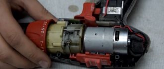
To service the motor rotor, it must be carefully removed from the stator.
If the contacts are charred or contaminated with scale, clean them with sandpaper as the engine rotates. The cause of burning may be contamination with fine dust or prolonged operation under extreme loads.
Ring the resistance between adjacent lamellas. It should be the same.
Then you should check the windings for electrical short circuit with the magnetic circuit housing.
If there is conductivity, the faulty winding should be rewinded. The same applies to broken wiring. Rewinding can be ordered from a specialized service or carried out independently.
You don't need to have a motor diagram for this (although that's not a problem). It is enough to count the number of turns of the winding and measure the diameter of the wire.
Stator repair
If overheated, the varnish insulating the turns of the main winding may melt, and an interturn short circuit will occur. The winding will burn out and the motor will stop working. Check as in the previous description. We ring the windings (there can be two or three of them), and rewind them if necessary.
How to select spare parts for replacement
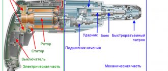
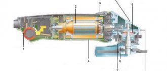
Lack of resistance indicates a break. Connecting an electric drill button Read about the principle of operation of the speed controller in the article about the device of a drill. Electric drill structure: 1 - stator, 2 - stator winding, second winding under the rotor, 3 - rotor, 4 - rotor commutator plates, 5 - brush holder with brush, 6 - reverse, 7 - speed controller.
It shows the existing electric motor speed controller with a rotor reverse control and reverse. This unit becomes clogged with dust during work.
If the light comes on, everything is fine with the button, but if you notice a malfunction, it’s time to replace the button. The stator is made of electrical steel with high magnetic permeability.
There are many cases when the parameters of the buttons match, but when installed in the drill case they simply do not fit.
When replacing a button, it should be taken into account that the circuit may have a fairly simple structure, or it may be made in reverse. When these components wear out, the reduction gearbox pair experiences increased loads.
This means that you should take care to clean the device after each use - this is the only way to reduce the risk of malfunctions due to contamination of the tool. Drills are different in type, but in terms of power, by the way, when buying a new drill button, you need to take into account the power of the tool, otherwise the button will not last long.
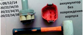
This article will help eliminate this gap. WEIGHT without power supply cable, socket and additional accessories. What's inside Drill repair. This happens very often, do it yourself
Design and malfunctions of an electric drill
Drills can come in different sizes and colors, but the pattern inside is always the same.
Impact drill device
The main components of an impact drill:
- Cartridge.
- Metal gearbox housing.
- Electric motor.
- Start button.
- Button to switch between normal and shock modes.
- Frame.
- Induction rings.
- Capacitor.
- Network cable.
- Brushes.
- Reverse button.
- Speed regulator.
A simple drill without an impact mechanism does not have a metal gear housing. The shaft and gear bearings are inserted into the drill body.
Hammerless drill gearbox
Basic drill malfunctions:
- Doesn't turn on. Causes: damage to the power cord, wires inside the drill, start button, or start capacitor.
- Engine malfunctions.
- Broken or worn brushes.
- Sparks, smokes, crackles, unpleasant smell. The reason is the brushes or the motor.
- Loss of power occurs due to a faulty armature.
- Damage to the power, reverse, and speed control buttons.
- Bearing wear.
- Poor chuck clamp.
Engine faults:
- Shaft deformation.
- Making an anchor.
- Failure to secure the poles to the frame in the stator.
- Winding wire rupture due to overload or abrasive dust.
- Short circuit to body or between turns.
All of these faults, with the exception of engine faults, are easy to fix yourself. Engine repair is possible if you have certain skills and knowledge. Sometimes it's easier to take it to a workshop or buy and install a new one. Installing any new unit is cheaper than repairing it in a workshop, since professionals charge a fee equal to the cost of the unit for one replacement.
Video: drill device
Recommendations for extending the performance of new and repaired drills:
- The drill should not operate for more than 20–25 minutes continuously after being plugged in.
- Do not overheat the device to the point of burning your hands.
- It is necessary to clean the cartridge from dirt and lubricate it.
- Do not use very dull drills.
The drill does not turn on, what should I do?
When connected to the network, there are no signs of life of the instrument. Experienced craftsmen have had to deal with this phenomenon more than once, but what to do if such a phenomenon happens for the first time? Disassemble, diagnose and repair the drill. Troubleshooting when the drill does not turn on begins with identifying the presence of voltage in the network. It’s trivial, but true - often the reason for a tool’s inoperability is the lack of voltage in the network. The reasons for this may be scheduled repairs at the transformer substation, tripping of circuit breakers, or damage to the power cord of the outlet. Take a multimeter and measure the voltage in the network.
If the socket is working, then the next suspect for a malfunction is the network cable. Yes, it also does not last forever, and can be damaged during the use of the tool. Do not try to find a breakdown visually, as this will be a waste of time. Take the tester and turn on the dialing mode, check the integrity of both wires. To do this, you need to disassemble the case and alternately touch one probe to the contact on the plug, and the second to the wire connected to the button. The cores are in good working order when the device “beeps”.
Typical tool failures
After completing drilling work, it is necessary to remove dust from the tool, especially from its ventilation holes. The nature of faults is divided into electrical or mechanical origin.
Electrical damage
This type of breakdown occurs due to exceeding the permissible load on the device and violations in its operation. They manifest themselves in the refusal of the tool to turn on, in a malfunction of the reverse or speed controller. Most often, to restore functionality, you will need to disassemble the start button and clean all places associated with the electrical contact.
The appearance of a burning smell indicates an overload in the operation of the electric motor. In this case, the condition of the brushes and windings is first checked, and the connection points of the power wire are examined to ensure there are no burns. Burning is associated with the ingress of dust, as a result of which the contact resistance increases, which leads to heating. Electrical faults are easily calculated using a multimeter and visual inspection.
Mechanical breakdowns
Mechanical faults are more difficult to detect. This kind of breakdown is usually accompanied by the appearance of extraneous sounds, and it will not be possible to eliminate them without disassembling the instrument. If the drill is poorly fixed in the chuck, it will need to be replaced, since the wear of the gear connection cannot be restored independently.
The appearance of a wedge during operation is associated with damage to the gearbox or bearing. If you disassemble the device, the damaged unit will be immediately visible. Wear on gears or splines will indicate the need to replace them. Bearings are checked by rocking them on the shaft. If the movement is not smooth or extraneous sounds are heard, then the bearing is replaced. After you manage to find the faulty unit and repair it, before putting the device back together, you need to clean the gearbox of old lubricant and apply new one. Then the device will be able to serve for more than one year.
Overhaul of three Soviet drills IE-1202, IE-1022, IE-1023A (with button modification).
Hello dear forum users, I want to talk about the overhaul and, in some places, modification of several Soviet-made electric drills.
I'll start with a rather interesting drill IE-1202 from the Konakovo plant.
Power consumption – 420 W (250 W – useful). Speed 960/2076 rpm. Standard key chuck 1-9 mm. Operating mode – S 1 (continuous).
There was already a topic in the forum about this drill with overhauling the gearbox and replacing the lubricant... So I’ll add a little to this topic with my photos and impressions))
So, general information about the drill:
- Very strong! Nothing dangles or wobbles, the plastic handle does not creak.
- An interesting two-speed gearbox in an aluminum housing (which is already a rarity for a modern tool). It’s very pleasant to work with two gears: if you need to quickly use a thin drill, we turn on the “second” one, and if you need a solid diameter and in strong metal, then the “first” one is just right.
- Compact size for such power (honest Soviet 400 W). Sometimes it’s hard to hold it in your hands, it tries to break free)).
- There is no speed control. This is a small minus; it is difficult to start drilling if the hole is not punched. At first I wanted to remake the button into a modern one with speed control, but the standard button works too clearly, so it was decided to leave it.
- Great spindle! No runouts, gaps, etc. Naturally, this does not apply to the standard chuck, which was poor, the drill “danced” in it, the jaws were flattened. The standard cartridge also has a small advantage - it is lightweight. The chuck is attached to the spindle not on a cone, but on an M12x1.25 thread. It was decided to immediately change the cartridge to an all-metal quick-release one, I came across a “Kraton” 0-13mm M12x1.25 BZP, of course China, but I liked it, the quality is acceptable, there are no beats, the jaws are hardened. This is where the disadvantage of this cartridge manifested itself - it is very HEAVY and long! It became very difficult to hold the drill in one hand, but it was comfortable to work, changing drills quickly and without a key.
- The insulation of the standard wire is cracked - definitely need to be replaced.
I changed the cable on the KG, as with all the power tools in my collection, installed 2x0.75, this is quite enough, the rubber insulation of the KG does not “dumb” in the cold, and the cable is softer, in general.
Now in more detail and with photographs))
So, IE-1202 drilling machine, bought by myself for a symbolic price on the local market, it’s hard to say the year, most likely the end of the 80s:
The new cartridge has already been screwed in and the screws of the handle cover have been unscrewed.
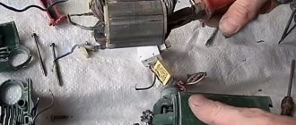
Under the cover we see a push-button switch, a brush assembly, and a capacitor for suppressing radio interference in a single housing has three terminals.
I am very pleased with the switch, it works well. It is also unusual - it lies horizontally, I have never seen anything like this before.
Each screw is filled with paint to prevent unscrewing, it really was made for centuries...
The brush assembly is made competently, each brush holder can be pulled out freely, in which the brush itself can be easily changed.
Everything was disassembled, cleaned, all the screws were tightened, and the power cable was replaced, as I already said. At this point, the electrical equipment was completed and disassembly of the gearbox began.
The gearbox is two-stage, two-speed, gears are helical, all shafts rotate on rolling bearings.
It was most likely lubricated with “Lithol” (brown cocoa inside the body, and the gears are dry).
Assembly for fastening and fixing the positions of the speed switch.
And of course, an assistant named Vintik, who was always trying to steal something from me, I just had to gape)))
The gear that directly changes the speed is located on the spindle shaft, along which it moves back and forth with the shift handle pin. Rotation is transmitted to the shaft from the gear through a key made in the form of a pin. A spring ring protects it from sliding further along the shaft.
Here is the entire gearbox disassembled, washed with white spirit and WD.
After everything was washed, the bearings were troubleshooted, some were replaced, the gearbox was assembled and filled with fresh MS-1000 grease. The drill began to work very quietly, the noise of the gearbox was inaudible. After the bulkhead, I drilled a lot of things into it, with drills from 3 to 13 mm, steel, cast iron. Hold it with both hands!))) The most versatile and well-thought-out drill in my collection.
The next drill is IE-1022 , probably the most common.
Power – 400 W, spindle speed – 700 rpm, largest drilling diameter – 14 mm, spindle with internal Morse taper No. 1, operating mode – S1 (continuous), button without speed control.
The chuck in my drill was in poor condition; moreover, it sat in the spindle through some kind of homemade clumsy adapter. Cartridge for spare parts, adapter for trash)
Features of this drilling machine:
- Spindle with internal Morse taper. Which by itself implies the use of drills and tools with a conical shank (I used a 14mm reamer). In addition, the spindle rotates on large rolling bearings, which is very reliable and eliminates spindle runout.
- Aluminum gear housing, the cylindrical part of which can be used to mount a drill in a rack.
- One of the disadvantages is the bulky design. But this is a plus, when drilling something massive for a long time with large drills, you can rest well))
- High torque and low speeds again hint at monotonous difficult work on metal with a large drill diameter. This is what she is designed for.
- It is better not to work with small drills (up to 5 mm); with such weight and dimensions, a slight misalignment or jamming of the drill often leads to its breakage. Also, with a large mass of the drilling machine, the force that is transmitted directly to the drill by hand ceases to be felt.
- The drill is designed for continuous long-term operation. Modern drills cannot boast of this, unless they are highly specialized professional tools.
To begin with, I cleaned and disassembled the handle made of very durable plastic, which, as always, contains all the “electrical guts”.
The button worked clearly and stably, but at first there was a desire to “stick on” the speed control like on the IE-1035E (later analogue). But after thinking a little, I decided to abandon the idea of replacing the button due to the complexity of its installation, and as a result, damage to the appearance of the handle. And the speed of the drill is so low. I determined its purpose for myself - it is drilling metal with 10-13 mm drills and possibly mixing various building mixtures (fortunately there is plenty of time). I cleaned the button, as well as all the insides of the handle, reconnected the power cable, which was already in rubber insulation, and changed the plug. Cleaned the commutator and checked the brushes. This completed the electrical part.
Next it was time for the gearbox. The gearbox is two-stage, the gear ratios are large, so the torque transmitted to the tool is pleasing, the main thing is to stand firmly on your feet)).
As always, there was “Litol” in the gearbox, not very thickened, but the gears were dry. Then wash everything, wipe off the old grease, and check the bearings. The spindle bearings were replaced because... the old ones probably worked dry for a long time and began to sing.
These are the serious gears that rotate the spindle.
A small digression, I want to describe in a little more detail the fit of the spindle gear. Everything was done very competently and repairable. There is a keyway at the free end of the spindle, and a gear is seated through the key, which is secured against sliding along the shaft by a locking split spring washer. I focused my attention on this point because when disassembling the next drill, I expected to see something similar, but that was not the case))) But more on that later.
Installed spindle.
A quick-release chuck, also originally from the USSR, on a factory mandrel took its place.
This completed the revision of this drilling machine and confirmed its readiness for harsh work)
And finally, probably the most interesting drill IE-1023A , we will install a button on it with speed control, in a slightly unusual way...
Characteristics: Power – 600 W , spindle speed – 234 rpm (3.9 s-1), largest drilling diameter – 23 mm , spindle with internal Morse taper No. 2, operating mode – S1 (continuous), button without speed control (which worked every other time). The year of release of my copy is 1983))
This is, frankly speaking, an exhibit)) But I don’t need it for beauty, but for work, so let’s get started.
There was also a topic on this drill about replacing the button, there is very little information on the Internet, I found a drawing from some book on power tools with a brief description and scope of application. Specifically: Drilling with a diameter of up to 23 mm; when mounting in a rack and using a crown - drilling holes in concrete; using this drill as a drive for a wall chaser; and also as an electric drive for an oil pump for a hydraulic pipe bender. Very versatile device)
Features of IE-1023A:
- Powerful engine
- A three-stage gearbox, combined with a motor, produces enormous torque. But all the torque goes to the spindle, without any safety clutches, etc., which is unsafe for humans.
- Original button without speed control, the engine starts immediately and at full speed. It is very inconvenient in combination with low speeds and large drills; it immediately begins to dance around the intended point.
- The weight of this drilling machine is about 5 kg.
The purpose follows from the characteristics - drilling with large diameters at low speeds, working with a tool having a shank with a Morse taper No. 2.
So, in my drill, the power button initially did not work well, it did not turn on the first time, and sometimes it turned off itself while drilling. The question immediately arose about replacing it. But simply changing the button is not so interesting, and after reading the forum, I also wanted a button with both adjustment and reverse.
Having disassembled the handle, I examined the button of an unusual shape, which, as it turned out, someone had already repaired; instead of pins or rivets, bitten nails were inserted. The button is designed for a current of 8A. But I didn’t want to repair it again, and, taking half of the handle in which there was a hole for the orange trigger lock button, I went to one of the service centers for repairing power tools, where there was a spare parts store. For me, the main criterion at that time was: the button should be adjustable and reverse, and fit as closely as possible in size (so as not to greatly damage the handle during installation).
Walking around the sales floor and looking at the available buttons, I didn’t see anything similar. One of the service center employees decided to help me with the choice, to which I showed him a pen and explained that I was looking for which button would be suitable. During the conversation, it turned out that the tool was very familiar, the original button, as expected, could not be found, and there was no similar one either. When I said about my desire to reverse the rotation of the rotor, they told me that they had encountered this, this drill has a stator winding made in a special way and if you force the armature to rotate in the opposite direction, there will be strong sparking of the brushes and the tool will fail. I decided to trust a person who, unlike me, had rewinded a power tool more than once, and abandoned the reverse idea, arguing for myself “well, this is not a screwdriver.” But I wasn’t going to give up adjusting the speed, and we started going through the buttons, based on the criterion that the holes for the trigger and the lock matched. Nothing fit. After which the consultant said “wait,” he took the ladder and reached into the bins somewhere, onto the top shelf and pulled out a new handle very similar to mine, but there were already holes in the plastic for new buttons. It turned out that this is a handle from modern Rebir drills, which are like two peas in a pod and replicate the Soviet tool. I was offered to buy both a handle and a button, but when I found out how much a new handle cost (700 rubles), the toad immediately squeezed my throat)) And it was not advisable, having a not broken handle, to buy a new one. In the end, it was decided to take only the adjustable button and somehow adapt it to the old handle.
Having connected the button to the drill, I checked the speed control, which made me very happy; the electrics worked like a clock.
I decided to install the button according to the principle of matching the hole under the latch, and cut a new one under the trigger itself; it turned out to be much higher than the previous one and not so wide. Having secured the button in the handle, I was satisfied with everything except the huge hole right under the trigger, left over from the previous one. Options such as “seal it with electrical tape and it will do” did not suit me, and I had to think a little. After which it was decided to “build up” the missing part of the handle using epoxy resin...
Let's look at the process and the result itself))
A “bath” was made from masking tape, and a piece of polyethylene foam from some packaging was placed under the new button to fill the space. After which the bath was filled with epoxy. The same thing was done on the second part of the handle, but in a mirror image. After that there was a painful wait while the resin hardened...
When the process was finally completed, I removed the tape and was surprised at the result))
Everything was smooth, there was even a collar along which the halves of the handle are joined...
From the outside, the result was very good; the junction of the epoxy and the plastic was not felt to the touch.
The button felt like it was original, the speed was regulated, the engine rustled softly. After which the electrical part of the drill was completed.
I would also like to pay attention to the size of the motor brushes, they are simply huge. They are pressed by powerful springs.
Next came the time to rebuild the gearbox.
The gearbox, surprisingly, was not lubricated with Litol, but with some kind of blue grease. It seemed to be on the gears, but the bearings (especially the engine) were here and there, smeared as if with brilliant green, and were spinning with a characteristic squeal. In addition, one unpleasant moment surfaced: the gear on the second intermediate shaft was stuck by welding, this made me think that this was someone’s repair, but the gears and shafts were clearly factory. This moment remains a mystery to me; was it really done this way from the factory???
Dry front engine bearing.
Here is such a “barrel” on a huge bearing, it just “smells” of lubricant)) You can imagine what loads the spindle is designed for...
Rotor. Another fact against reverse rotation of the rotor is the bent blades of the fan impeller; if you force it to rotate in the opposite direction, the cooling will be ineffective.
After everything was washed from the old grease inside the gearbox, it was necessary to remove the spindle, BUT...
The gear on the spindle was fastened incomprehensibly to me, there was no retaining ring, the key was not visible (remember the fastening on the IE-1022), as if it had been set hot... Without removing this gear, it was not possible to pull out the spindle, so it was decided to leave everything as is, especially Moreover, there were no backlashes observed, and the size and low-speed bearings predicted a long life for them. The only negative is that I did not get to the inner bearing of the spindle and did not change the lubricant there. If anyone else has disassembled this drill, please share how you pulled out the spindle.
The gearbox was again filled with new MS-1000 grease and closed, the drill was put back together and a test run showed that the noise had noticeably decreased, and it became very pleasant to work with adjusting the speed.
By the way, the cartridge found in my grandfather’s bins in the barn fit perfectly, after cleaning it from centuries-old dirt and rust, it turned out that it was a Novosibirsk cartridge from 3 to 16 mm of a very ancient year of manufacture with a fit under the internal cone B16, in very good condition . The cartridge does not hit, has no damage, the jaws are even, so it was decided to use it as the main equipment. All this was matched with a Chinese mandrel (B16 MT2 shank) that I ordered. Which pleased me with the quality of workmanship and the price half that of the Russian rusty analogue from the market and four times the price than the same Chinese one in the service center)).
Cartridge 3-16 mm with a mandrel for Morse taper No. 2.
Keyless chuck 1-13 mm.
Mandrel B12 for Morse taper No. 1.
Adapter Morse cone No. 1 to Morse cone No. 2.
So there are a lot of options for mounting the tool.
So my humble story about some worthy representatives of hand-held power tools from the times of the USSR has come to an end, I hope that it will be useful to someone.
Low power electric drills
For low-power tools, the spindle at the end is equipped with a right-hand external thread, onto which the chuck is screwed. In its central part there is a hole, but with a left-hand thread for a shunt bolt. This fastener has a head designed for a square or Phillips screwdriver. It needs to be unscrewed.
Further, doing the repair of the drill chuck yourself comes down to the following. First you need to block the engine impeller, which can be done with a nail. Then try to tear off the cartridge in a counterclockwise direction with a sharp but moderate force movement.
Complex equipment
Models of tools with power from 600 to 800 W are distinguished by a wedge-cone chuck fit. The spindle is a sleeve into which the shank of the collet chuck fits. To remove it, you need to find a hole on the side of the bushing and insert a powerful screwdriver there. Use it to pry the end of the shank and push it out.
However, there may not be a hole. Then the bushing must be clamped in a vice and the cartridge must be struck with a hammer of medium force through a piece of wood. They should not be chaotic - they should be alternated at diametrically opposite points on four sides.
Electric drill motor start button
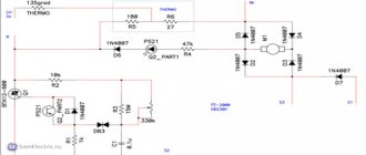
What a shame when something breaks at the most inopportune moment. Especially with current prices. For example, the start button of a drill often flies and at the same moment you wonder what flew this time? And then bam! Button! Infection! That's it, let's go buy a new one. But that's bad luck! We didn’t remember the location of the pins, what went where. And here the diagram will come in handy for you. Connection with 3-lead capacitor:
This also happens:
Reverse button:
In order for the engine to start working in the opposite direction, you need to swap the connections of the wires to the brushes (in a button with reverse, this is done using the switch lever). I would like to draw your attention when purchasing a button, it must match not only the size, but also the power of your drill. Let's do the math: we have a drill with a power of 650W, P=U*I, I=650/220=2.95A, . It turns out we need a button with U=~220V, I=at least 2.95A, which means the BUE-3~220V 3.0A button will suit us.
It turns out we need a button with U=~220V, I=at least 2.95A, which means the BUE-3~220V 3.0A button will suit us.
Lubrication of drive train, bearings and spindle
Removing the housing.
Unscrew the gear housing and remove it from the engine housing. Carefully set the gasket aside for reassembly. Wear rubber gloves and wipe off the old grease with a clean cloth. Lift the gear and pinion, noting their location for reassembly.
Cleaning the gear.
Clean with an old brush dipped in paint thinner. If the drive train is pressed against the spindle and housing, clean them in place using a cloth. A damaged spindle or gear should be replaced. To replace the entire gear housing, screw it back down to remove the chuck and then unscrew it again.
Fill the gear housing halfway with clean lubricant specified by the manufacturer. Apply a few drops of SAE 20 engine oil to each hub bearing in the motor housing. Reinstall the gasket and screw it back onto the gear housing.
Replace the damaged gasket with an exact copy.
Wiring diagram for a shovel drill switch
Quite often, an electric drill stops working due to a breakdown of its speed control switch (it does not turn on, the speed cannot be adjusted), we disassemble the drill, try to do something, and when we realize that the problem is in the speed control switch, there are many wires from it already torn off and which one was unknown where. To solve this problem, you will need information: how to replace an adjustable switch on a drill: In order for the motor to start working in the opposite direction, you need to swap the connections of the wires to the brushes (in a button with reverse, this is done using the switch lever)
I would like to draw your attention when purchasing a switch, it must match not only the size, but also the power of your drill. Let's do the math: we have a drill with a power of 650W, P=U*I, I=650/220=2.95A, it turns out we need a switch for U=~220V, I=at least 2.95A, which means the BUE-3 switch is suitable for us ~ 220V 3.0A
It is also advisable to install new capacitors (capacitance) when replacing a switch with speed control.
repair
This is interesting: Decorating the front door from the inside
Safety and subtleties of choice
A hand drill is a simple tool that does not require special skills to operate. However, as when working with other devices, it is necessary to follow simple rules to minimize the likelihood of damage to the working part or injury to a person:
- the workpiece must be fixed - with any attempts to hold it with your hands, situations quite often arise when the part is pulled out of your fingers, causing injuries along the way;
- do not touch the drill with your hand without making sure that it has cooled down (burns are not uncommon, especially if metal was drilled);
- after replacing the drill, do not forget the key in the chuck;
- when drilling at high speed, to avoid overheating of the drill, it is better to take breaks - and the drill will be more intact, and the work will ultimately be done better;
- Using glasses will protect your eyes from chips.
When choosing a hand drill, you should pay attention to the convenience of the handles, the smooth rotation of the mechanism, and the accuracy of execution. The body should not have burrs, sharp protruding edges, or other signs of poor quality manufacturing. Negligence in execution, as a rule, indicates low quality production, which negatively affects the product.
As practice shows, a mechanical drill is still in demand, despite the fact that today there is a huge selection of “electricians”. It is clear that working with this tool is more tedious and slower compared to drilling with an electric drill or screwdriver, so in professional work a hand drill is used quite rarely. However, for simple household tasks, this tool can be effective and practical, allowing you to do the same work without access to an electrical outlet, without rushing, but keeping the process completely under control.
Drill device
Regardless of the manufacturer and additional options, an electric drill consists of a standard set of components:
- Network cable. Despite the elementary nature of this unit, 50% of so-called malfunctions are associated with it. The power wire simply breaks. Typical break points are the entry point into the handle and the soldering of the start button contacts (especially if the switch body has a seat play and moves when the key is pressed)
- Spark suppression capacitor
- Start button. Weak point - after checking the cable, we test this element
- External winding (stator) of the motor
- Motor rotor support bearing
- Brush units - holders and current collection brushes themselves
- Motor rotor contact manifold. The cleanliness of its contacts is the key to uniform rotation
- Drill body
- Engine cooling fan
- Operating mode switch. Depending on the model, reverse the gearbox or connect the impact mechanism of a hammer drill. Drive mechanical or contact
- Gearbox housing. Present on every model; the cartridge is not directly attached to the rotor axis
- Reducer gears. If a large amount of dust gets in, the lubricant loses its properties. The gearbox wears out quickly and requires replacement
- Chuck bearings. Carry a heavy load and require maintenance
- Chuck axis. In hammer drills it is equipped with a return spring
- Drill chuck. The collet mechanism can be quick-clamping or turnkey.
Do-it-yourself drill repair begins with checking the functionality of all components.
It is usually not possible to completely disassemble the instrument. But we must be prepared for such a turn.
How to identify a faulty brush assembly
Drill brushes, which are a consumable item, fail. The brushes are made of graphite, and with their help, current is transferred to the rotor through the commutator unit. During operation, brushes wear out, burn out, wear out and require replacement. The service life of brushes depends on various factors:
- Quality
- Collector serviceability
- Power tool load
A brush malfunction can be identified by signs such as excessive sparking. If, before the drill stopped starting, there was excessive sparking with signs of carbon deposits, then it is highly likely that the carbon brushes need to be replaced. To replace, you need to remove the elements from the brush holders, remove the worn parts and install new ones in their place.
This is interesting!
If the brushes are worn more than 60% of the original length, they must be replaced.
In addition to the malfunction of the brushes, it is necessary to pay attention to the condition of the copper lamellas of the commutator. If there are signs of soot on the copper base, as well as chips and other defects, then all this should be eliminated. If you cannot fix it yourself, then you should replace the anchor. The cause of carbon deposits on copper plates is excessive sparking of the power tool. In addition, if the commutator is heavily worn, a connection (short circuit) between the plates occurs, which is also unacceptable.
Repair of a button with speed control
Figure 2. Diagram of a speed controller for a microdrill.
Repairing a button is a rather complicated process that requires certain skills. When opening the case, some parts may simply fall out and get lost.
Therefore, caution is needed in work. In case of problems, the triac usually fails
This part is very cheap. Disassembly and repair occur in the following order:
- Disassemble the button housing.
- Rinse and clean the insides.
- Remove the board with the circuit on it.
- Remove the burnt part.
- Solder a new part.
It is very easy to disassemble the case. You need to bend the sides and remove the cover from the latches
Everything must be done carefully and carefully so as not to lose 2 springs that may jump out. It is recommended to clean and wipe the insides with alcohol
Clip-contacts in the shape of copper squares slide out of the grooves, and the board is easily removed. A burnt triac is usually clearly visible. All that remains is to unsolder it and solder a new part in its place. The regulator is reassembled in the reverse order.
Symptoms of electric drill problems
Every electric drill system can fail. You can determine the causes of a malfunction by knowing their main symptoms.
Mechanical defects
The following signs indicate that the problem lies in one of the mechanical devices:
- jamming of the cartridge, inability to turn it by hand;
- metallic knocking and grinding noises during operation;
- crunch of plastic inside the case;
- hum of worn-out bearings, increased vibration;
- the impact mechanism does not turn on;
- the cartridge flies off the working shaft.
Mechanical failure can lead to malfunctions that occur periodically. Don't expect it to correct itself. As soon as the first signs of a problem are detected, it is necessary to stop work and eliminate the defect. Otherwise, the cost of repairs will increase significantly.
Signs of electrical failure
The electrical part also has its own characteristic signs of malfunction:
- the drill does not start, the motor does not rotate;
- the motor hums, but does not work;
- brushes spark strongly;
- The speed controller does not work, the speed does not change;
- The reverse does not work, the cartridge rotates only in one direction;
- the engine runs unstably, sometimes breaking at high speeds;
- there is a characteristic smell of smoldering wiring;
- The drill body gets hot.
Checking the electric motor: causes of breakdowns and repairs
Drills, like many rotary hammers, often stop working due to motor failure. There are two reasons why it may fail:
- Incorrect use. Some people often overload the devices and therefore the motor stops working. In this case, it is easier to purchase a new drill.
- Bad coil wire. Most often, this problem occurs when using budget models. It is better not to replace the wire yourself. This is a job for professionals.
Types of faults in the electrical and mechanical parts of the drill
The most common electrical problems are when the drill sparks at the brushes due to significant grinding or wear. A device with heavily worn brushes will not turn on at all. A sign of problems with the engine is the absence of signs of its activation (sound, vibration, etc.). For a drill with variable speed control, reverse and speed control may no longer function.
Mechanical faults - failure of a bearing or gear mechanism, shaft failure. They are manifested by humming, periodic stops of the device, and slow rotation. Sometimes problems arise with the chuck: difficulties in disconnecting the drill, unscrewing the chuck relative to the shaft.
General rules for repairing power tools
The safety rules for repairing an angle grinder are the same as for repairing any other power tool. Cleaning from dust, disassembling and assembling is carried out only with the device completely de-energized. Repair work must be carried out on a dielectric surface, and the power source must be equipped with a short circuit protection circuit breaker. It is strictly forbidden to manually turn the angle grinder spindle if the power supply is turned on. It is also prohibited to carry out test runs during or after repair with a cutting disc installed on the spindle.
Mechanical hand drill. Greetings from the USSR
Today, with the availability of power tools, such simple and reliable devices as a mechanical hand drill are often undeservedly forgotten. Meanwhile, even being inferior in its capabilities to electric models, this tool remains practical, autonomous and extremely economical, and under certain conditions may be a better option for drilling or working with fasteners.
How to replace brushes: work in a couple of minutes
But the drill may not work due to trivial faults - for example, due to brushes inside the motor. This means that you can’t do without repairing brushes, and this work is quite simple - you don’t even need to have special knowledge and tools. To do this, we disassemble the device, remove the brush holders from it and replace parts that are broken. By the way, there are models whose body does not need to be disassembled - you just need to remove special plugs through the installation window, after which we change the brushes.
You can purchase these parts at any hardware store; there are also some models that are sold together with a set of additional brushes
It is important that you do not wait until the brushes are completely worn out - check them from time to time. And all due to the fact that there is a risk of a gap forming between the bristles and the collector
As a result, this part will begin to overheat and eventually fall off - which means you will have to change the entire anchor, which will be much more expensive and more difficult, and it is not a fact that you will be able to solve this issue yourself.
As you can see, there are a variety of breakdowns, many of which will be within your control, others will only be possible for specialists in service centers. And to reduce the risk of such breakdowns, you need to take care of your tool, clean it after work, check the condition of the parts and brushes in order to replace them with new ones in time. However, if you see that you can’t handle it yourself, take the device to a workshop.
Brushes
Another common problem with electric drills is wear on the motor brushes. When they are ground down by 40%, interruptions in the operation of the drill and even sparks can be detected. With an even greater degree of wear, the power unit simply will not start. Replacing outdated parts at home is not that difficult.
Some models have the ability to do electrical repairs yourself. drills (in particular, replacing brushes) without opening the case. There are special plugs for this. It is enough to unscrew them and replace the old worn brushes with new ones. When choosing new parts, you should pay attention not only to their dimensions, but also to the cross-sectional profile.
You should not allow the brushes to wear too much, as this can lead to a number of troubles. Firstly, the gap between them and the collector plates increases, which leads to increased sparking. Secondly, because of this, the plates become very hot, as a result of which they can move away from the base of the collector. This may result in the need to replace the armature.
Button repair
For some models of electric drills, this part is equipped with an electric motor speed regulator, and also has a regulator for the direction of rotor rotation (reverse)
This is a fairly complex design, so repairing the button should be carried out with a high degree of care. Often, after disassembly, further use is not possible.
Inside the button of such a complex device there are many small parts that can fall out when the case is opened. They get lost easily and are difficult to put back in their original place.
Therefore, this part of the work should be performed with increased attention.
After careful disassembly, you should clean the terminals from carbon deposits (perhaps that is why the current did not pass) and reassemble everything in the reverse order. Next you need to check the button for functionality.