What characteristics should a garage lift have?
Since the device will be used in the rather cramped conditions of a standard garage, certain requirements are put forward for it.
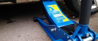
Firstly, it should not be too large - such a car lift, despite its high power, takes up a lot of space, which is very undesirable in such a small area. Secondly, it is recommended to give preference to mechanisms with a small vertical stroke, otherwise you risk running into the ceiling. The second requirement is carrying capacity. It is calculated based on the types of work for which the car lift is being developed. The dimensions of the mechanism also depend on the purpose. If a regular jack is suitable for regular wheel replacement, then for larger-scale work you will need a car lift with a platform, although for such important actions it is recommended to resort to the help of professional equipment.
Tower crane lifting capacity 15 tons
rihhansu
December 8, 2021
11 400
Graduation project. Contains drawings immediately in all convenient formats for editing and printing Compass-3D, AutoCAD, pdf, jpg, cdw, dwg: tower crane (general view drawing with specification in A1 format); drum with specification; shaft drawing on 4 A3 sheets (operational sketches, axis); tower crane slewing mechanism with specification; mechanism
Cranes / Tower cranes
DIY crane assembly technology
If you have certain skills, assembling the mechanism yourself will not be difficult.
To do this, it is important to draw up a preliminary design drawing, choose materials wisely and strictly follow the assembly instructions
Schemes and drawings
Below are sample drawings of a hydraulic crane. You need to make accurate calculations yourself, based on the parameters of a particular garage.
Material selection
To build a garage lift yourself, it is recommended to first purchase all the required materials:
- 3 steel corners with parameters 7.5x7.5x0.8 centimeters.
- “Worm” gearbox, the minimum load capacity of which starts from 300 kilograms, and the additional indicator is 60 kilograms.
- A strong steel plate one centimeter thick. If you have an old metal cutting machine, you can take it from it; you won’t need outside help for this.
- About 10 matching bolts.
- 2 dense metal chains with a diameter of two to three centimeters. The crane is designed to work with very heavy materials - you should carefully monitor the quality of the metal.
- Hook.
- Steel cable with a diameter of 5 millimeters.
- 2 keys with different parameters in the shape of an asterisk.
Step-by-step construction instructions
The process of assembling and installing a homemade garage crane does not look complicated:
- steel corners must be installed on parallel walls;
- fasten the steel plate to them using M8 bolts;
- fix the “worm” gearbox on the plate;
- install a larger key on the drive shaft;
- drill a hole in a pre-designated place, insert a chain into it and close it into a ring;
- fix a smaller key on the output shaft of the gearbox;
- drill 2 more holes in the plate;
- pass the second chain through the holes, where one end is on a small key, and a hook is installed on the second.
Installing a faucet yourself has a number of important advantages. For example, the cost of a homemade mechanism is almost two times lower than a purchased one.
Main types of equipment
The average garage has a reduced square footage and requires careful selection of equipment. Before installation, it is recommended to carefully study the need for individual mechanisms, their types, pros and cons. A hydraulic valve is determined by two criteria.
By type of drive
There are also two subtypes of hydraulic drive:
- automated design with hydraulic cylinders;
- combined, with hydraulic cylinders and manual winches.
A significant drawback of the first is oil cylinders. They need frequent regular replacement, so this design is considered extremely unprofitable for constant use. The combined system will last longer. However, some of the work with winches will have to be taken on by mechanics.
According to the design of the support
Hydraulic cranes are divided into mobile and stationary, they can be folding and prefabricated cast (goose). For ordinary garages, it is more rational to choose a mobile structure with folding parts.
Installation of lifting mechanism
The main element of the crane is the lifting mechanism, which can be manual or automatic. The tefler consists of a cable and a winch installed on the side of the rack. The cable moves due to the rotation of the rollers. Additional fixation of the elements is not required; it is enough to secure the lift to the rack.
A self-made crane can be equipped with lifting equipment that is used in elevators. Such mechanisms are highly reliable and able to withstand massive objects.
To simplify repair work, it is possible to connect an electric drive to the lifting element. To automate the design, a motor with a power of 300-500 W is suitable. The electric drive is mounted to the base of the crane beam.
The design, equipped with an electric drive, is widely used in large-scale garage repairs and car disassembly for spare parts when a complex of work is required. According to the principle of operation, manual and automated cranes do not have significant differences.
Experienced car owners say that a crane beam is rarely needed in the garage, but if it is needed, there is nothing to replace it with. It is used for removing and installing the engine, and less often for moving other loads. Purchased mechanisms are expensive and take up a lot of space, so the best solution for a private craftsman is a do-it-yourself beam crane made from scrap materials.
In order to make a garage lift with your own hands, you will need:
- For racks - pipe with a cross-section of 100x100, length 2350 mm - 2 pcs.
- For the cross rod - a round pipe with a diameter of 100 mm and a length of 4150 mm.
- For supports – round pipe with a diameter of 110 mm and a length of 600 mm – 2 pcs.
- For bases and diagonal supports - corner 100x100 mm.
- M 16 bolts for attaching supports to rods.
- Wheels (for example, from a warehouse cart) – 4 pcs.
- Manual winch with a lifting capacity of up to 1 ton.
- Cable and rollers (for example, from an elevator door drive).
A beam crane is necessary for moving various loads
Crane beam device
The mechanism is a U-shaped structure (bridge) with a lifting mechanism. In large auto repair shops, both parts may be movable. The bridge moves on rails, the lift moves on a span beam. In garages, to save space, rails are not laid, and the bridge is equipped with wheels.
The crane beam device consists of supports, a span beam and a lifting mechanism. The supports are welded from metal pipes and channel bars. A manual or, less commonly, electric winch is used as a lifting mechanism.
Girder cranes are of the "floor operated" type, as opposed to those that are handled from a cab. To make the mechanic's work easier, the garage crane can be equipped with an electric winch
. This will increase manufacturing and maintenance costs, but if it is necessary to frequently dismantle engines and other heavy units, it will pay for itself. In rural areas where there are power outages, insufficient power or voltage surges, you should give preference to a manual winch. Especially if we are talking about a personal garage and not a private workshop.
Above we looked at what a beam crane consists of: supports, a span beam and a hoist. Manufacturing takes place in several stages:
- Weld the vertical supports in the shape of an inverted T with two diagonal supports.
- Weld the span pipe to form a U-shaped structure.
- Install the wheels.
- Weld a winch to one of the side supports.
- Install the lifting mechanism: fix the rollers, stretch the cable and hang the hook.
Ready-made drawings can be found online, but it’s easier to make it yourself by adjusting the product to the size of the garage.
Crane drawing
If for some reason this type of lift is not suitable, you can make a goose garage crane with your own hands - it will take even less time. The gooseneck crane has an L-shape, where the vertical stand is equipped with a jack rather than a winch. It is rolled under the car from the front and the engine is lifted by pumping a hydraulic jack. The boom moves upward and lifts the load.
Another interesting solution that will help save space is a suspended crane beam. Unlike the supporting structure described above, the span beam is attached to the ceiling by means of a rail (I-beam). This option requires sufficient ceiling height and strength of the building.
All devices must be tested with a load 20% greater than the maximum intended load.
Assembly of the structure
- rope;
- washers;
- corners and channels;
- pipe;
- grinder;
- welding machine.
The frame should be made of steel angle 63x63x5 mm. A 5 m long boom is made from a pipe having a diameter of 55 mm. To strengthen the unit, use corners measuring 30x30x3 mm.
The lifting capacity of such a homemade crane will be about 150 kg. If it is necessary to lift panels with a larger mass, then it is necessary to increase the multiplicity of pulleys, which are a device for lifting loads. The chain hoist is made from blocks, connected to each other with a cable. This cable should wrap the blocks in a circle. The pulley allows you to lift the panels using less force than the weight of the load.
The pulley system is 3-4 times stronger. In this case, friction losses are taken into account, which amount to 10%. The greater the gain in strength, the shorter the distance the tool can move the panels.
You can prepare and make all the details in 7-10 days.
Another 2 days are needed to assemble the mechanism. The lifting scheme is made in the form of a 2-fold pulley. The boom rotation unit is a 6-fold chain hoist. The turntable is made by attaching 2 washers. The axle replaces the 30mm bolt.
To reduce the size of the counterweights, the support legs are made 2 m long. With a turning radius of the washer of 200 mm and a distance of 2 m to the counterweight of 100 kg, a load of 1 ton will be applied to the bolt. This is taken into account when calculating the design of the tool. Perform stability calculations.
The structure is taken as a single system on one support. It is the smallest distance from the axis of rotation. The system is affected by: the weight of the load, the counterweight and the crane. The lifting drum is made from a pipe with a cross-section of 100 mm. It should not be installed close to blocks. It is fixed closer to the washers.
Blocks are made of 3 washers. They must be wrapped around the cord, the diameter of the blocks must be large so that the ropes do not fly out of the washers. The blocks are fixed without bearings.
Read also: Cyclone water filter
You need a flexible cable with a cross section of 5 mm. Its working load is 150 kg, and its breaking load is 850 kg. The pulley operates on the principle of a lever. For a chain hoist, the main indicator is its multiplicity (the ratio of all cable branches to those extending from the drum).
If the cord has 6 parts, then the pulling force on the drum will be 6 times less than the weight of the load. If a rope is made to lift a 100 kg load, then folded 6 times, it will lift a load weighing 600 kg. When all the systems are ready, you need to assemble them according to the drawn up design diagram, taking into account all the dimensions and rules for fastening components and parts. After assembly, you need to lubricate all structural systems and its individual parts with Lysol.
Following all the instructions described above, you can independently make a crane for building a house and any outbuildings used on the farm. Before starting operation, you should check the functionality of all components of the created crane structure. Then carry out a verification test of the equipment for the ability to lift and move loads.
Lifting machines are designed to help a person lift something heavy to a height. Most lifting mechanisms are based on a simple block system - a pulley system. It was known to Archimedes, but now many people do not know about this brilliant invention. Remembering your physics course, find out how such a mechanism works, its structure and scope. Having understood the classification, you can begin to calculate. For everything to work out, here are instructions for constructing a simple model.
Block system - theory
The invention of the chain hoist gave a huge impetus to the development of civilizations. The block system helped build huge structures, many of which have survived to this day and puzzle modern builders. Shipbuilding also improved, and people were able to travel great distances. It's time to figure out what it is - a chain hoist and find out where it can be used today.
Simplicity and efficiency of the mechanism
Structure of the lifting mechanism
A classic chain hoist is a mechanism that consists of two main elements: a pulley; flexible connection
The simplest diagram: 1 – movable block, 2 – fixed, 3 – rope
A pulley is a metal wheel that has a special groove for a cable along its outer edge. An ordinary cable or rope can be used as a flexible connection. If the load is heavy enough, ropes made of synthetic fibers or steel ropes and even chains are used. To ensure that the pulley rotates easily, without jumping or jamming, roller bearings are used. All elements that move are lubricated.
One pulley is called a block. A pulley block is a system of blocks for lifting loads. The blocks in the lifting mechanism can be stationary (rigidly fixed) and movable (when the axis changes position during operation). One part of the pulley is attached to a fixed support, the other to the load. Movable rollers are located on the load side.
Fixed block
The role of the stationary block is to change the direction of movement of the rope and the action of the applied force. The role of the mobile is to gain strength.
Movable block
How it works - what's the secret?
The operating principle of a pulley block is similar to a lever: the force that needs to be applied becomes several times smaller, while the work is performed in the same volume. The role of the lever is played by the cable. In the operation of a chain hoist, the gain in strength is important, so the resulting loss in distance is not taken into account.
Depending on the design of the pulley, the gain in strength may be different. The simplest mechanism of two pulleys gives approximately a twofold gain, of three - threefold, and so on. The increase in distance is calculated using the same principle. To operate a simple pulley, you need a cable twice as long as the lifting height, and if you use a set of four blocks, then the length of the cable increases in direct proportion to four times.
Operating principle of the block system
In what areas is the block system used?
A chain hoist is a faithful assistant in a warehouse, in production, and in the transport sector. It is used wherever force needs to be used to move all kinds of loads. The system is widely used in construction.
Despite the fact that most of the heavy work is performed by construction equipment (cranes), the chain hoist has found a place in the design of load-handling mechanisms. The block system (pulley block) is a component of such lifting mechanisms as a winch, hoist, and construction equipment (various types of cranes, bulldozer, excavator).
In addition to the construction industry, pulleys are widely used in organizing rescue operations. The principle of operation remains the same, but the design is slightly modified. Rescue equipment is made of durable rope and carabiners are used. For devices of this purpose, it is important that the entire system is quickly assembled and does not require additional mechanisms.
Pulley hoist as part of a crane hook
Classification of models according to different characteristics
There are many executions of one idea - a system of blocks connected by rope. They are differentiated depending on the method of application and design features. Get to know the different types of lifts, find out what their purpose is and how the device differs.
Classification depending on the complexity of the mechanism
Depending on the complexity of the mechanism, simple ones are distinguished; complex; complex chain hoists.
Example of even models
A simple chain hoist is a system of series-connected rollers. All movable and fixed blocks, as well as the load itself, are combined by one cable. Even and odd simple pulleys are differentiated.
Even lifting mechanisms are those whose end of the cable is attached to a fixed support - a station. All combinations in this case will be considered even. And if the end of the rope is attached directly to the load or the place where the force is applied, this structure and all its derivatives will be called odd.
Odd chain hoist diagram
A complex pulley system can be called a pulley system. In this case, not individual blocks are connected in series, but entire combinations that can be used on their own. Roughly speaking, in this case one mechanism sets in motion another similar one.
Combining a two-fold and six-fold simple chain hoist gives a complex six-fold version
The complex chain hoist does not belong to one or the other type. Its distinctive feature is rollers moving towards the load. The complex model can include both simple and complex chain hoists.
Classification according to the purpose of the lift
Depending on what they want to get when using a chain hoist, they are divided into:
A – power version, B – high-speed
The power option is used more often. As the name suggests, its task is to ensure a gain in strength. Since significant gains require equally significant losses in distance, losses in speed are also inevitable. For example, for a 4:1 system, when lifting a load one meter, you need to pull 4 meters of cable, which slows down the work.
The high-speed chain hoist, by its principle, is a reverse power design. It does not give a gain in strength, its goal is speed. Used to speed up work at the expense of the applied effort.
Multiplicity is the main characteristic.
The main indicator that people pay attention to when organizing cargo lifting is the multiplicity of the pulley. This parameter conventionally indicates how many times the mechanism allows you to win in strength. In fact, the multiplicity shows how many branches of the rope the weight of the load is distributed over.
Kinematic ratio
The multiplicity is divided into kinematic (equal to the number of kinks in the rope) and force, which is calculated taking into account the cable’s overcoming the friction force and the non-ideal efficiency of the rollers. The reference books contain tables that display the dependence of the power factor on the kinematic factor at different block efficiencies.
As can be seen from the table, the force multiplicity differs significantly from the kinematic one. With a low roller efficiency (94%), the actual gain in strength of a 7:1 pulley will be less than the gain of a six-fold pulley with a block efficiency of 96%.
Schemes of pulleys of different multiplicities
Read also: The most expensive lathe in the world
How to make calculations for a chain hoist
Despite the fact that theoretically the design of a pulley hoist is extremely simple, in practice it is not always clear how to lift a load using blocks. How to understand what multiplicity is needed, how to find out the efficiency of the lift and each block separately. In order to find answers to these questions, you need to perform calculations.
Calculation of a separate block
The calculation of the chain hoist must be performed due to the fact that the working conditions are far from ideal. The mechanism is subject to frictional forces as a result of the movement of the cable along the pulley, as a result of the rotation of the roller itself, no matter what bearings are used.
In addition, flexible and pliable rope is rarely used on a construction site or as part of construction equipment. Steel rope or chain has much greater rigidity. Since bending such a cable when running against a block requires additional force, it must also be taken into account.
For the calculation, the moment equation for the pulley relative to the axis is derived:
SrunR = SrunR + q SrunR + Nfr (1)
Formula 1 shows the moments of such forces:
– Srun – force from the side of the escape rope;
– Srun – force from the oncoming rope;
– q Srun – force for bending/unbending the rope, taking into account its rigidity q;
– Nf – friction force in the block, taking into account the friction coefficient f.
To determine the moment, all forces are multiplied by the arm - the radius of the block R or the radius of the sleeve r.
The force of the approaching and escaping cable arises as a result of the interaction and friction of the rope threads. Since the force for bending/extension of the cable is significantly less than the others, when calculating the effect on the block axis, this value is often neglected:
N = 2 Srun×sinα (2)
In this equation:
– N – impact on the pulley axis;
– Srun – force from the oncoming rope (taken to be approximately equal to Srun;
– α – angle of deviation from the axis.
Pull block block
Calculation of the useful action of the block
As you know, efficiency is the efficiency factor, that is, how effective the work performed was. It is calculated as the ratio of work completed and work expended. In the case of a pulley block, the formula is applied:
ηb = Srun/ Srun = 1/(1 + q + 2fsinα×d/D) (3)
– 3 ηb – block efficiency;
– d and D – respectively, the diameter of the bushing and the pulley itself;
– q – rigidity coefficient of flexible connection (rope); f – friction coefficient;
– α – angle of deviation from the axis.
From this formula it can be seen that the efficiency is affected by the structure of the block (through the f coefficient), its size (through the d/D ratio) and the rope material (q coefficient). The maximum efficiency value can be achieved using bronze bushings and rolling bearings (up to 98%). Sliding bearings will provide up to 96% efficiency.
The diagram shows all the forces S on different branches of the rope
How to calculate the efficiency of the entire system
The lifting mechanism consists of several blocks. The total efficiency of a pulley block is not equal to the arithmetic sum of all individual components. For the calculation, they use a much more complex formula, or rather, a system of equations, where all forces are expressed through the value of the primary S0 and the efficiency of the mechanism:
Efficiency of a chain hoist at different magnifications
Since the efficiency value is always less than 1, with each new block and equation in the system, the value of Sn will rapidly decrease. The total efficiency of the pulley will depend not only on ηb, but also on the number of these blocks - the multiplicity of the system. Using the table, you can find ηp for systems with different numbers of blocks at different efficiency values of each.
How to make a lift with your own hands
In construction, during installation work, it is not always possible to fit a crane. Then the question arises of how to lift the load with a rope. And here a simple chain hoist finds its application. To make it and fully operate, you need to make calculations, drawings, and choose the right rope and blocks.
Different schemes of simple and complex lifts
Preparation of the base - diagram and drawing
Before you start building a chain hoist with your own hands, you need to carefully study the drawings and choose a suitable scheme for yourself. You should rely on how it will be more convenient for you to place the structure, what blocks and cable are available.
It happens that the lifting capacity of the pulley blocks is not enough, and there is no time or opportunity to build a complex multiple lifting mechanism. Then double chain hoists are used, which are a combination of two single ones. This device can also lift the load so that it moves strictly vertically, without distortions.
Drawings of a dual model in different variations
How to choose a rope and block
The most important role in building a chain hoist with your own hands is played by the rope. It is important that it does not stretch. Such ropes are called static. Stretching and deformation of a flexible connection causes serious losses in work efficiency. For a homemade mechanism, a synthetic cable is suitable; the thickness depends on the weight of the load.
The material and quality of the blocks are indicators that will provide homemade lifting devices with the calculated load capacity. Depending on the bearings that are installed in the block, its efficiency changes and this is already taken into account in the calculations.
But how can you lift a load to a height with your own hands and not drop it? To protect the load from possible reverse movement, you can install a special locking block that allows the rope to move only in one direction - the desired direction.
Roller along which the rope moves
Step-by-step instructions for lifting a load through a block
When the rope and blocks are ready, the diagram has been selected, and the calculations have been made, you can begin assembly. For a simple double pulley you will need:
– clip for the block – 2 pcs.;
- rope; hook for hanging cargo;
– slings – if they are needed for installation.
Carabiners are used for quick connection
Step-by-step lifting of the load to a height is carried out as follows:
1. Connect the rollers, bushing and bearings. They combine all this into a clip. Get a block.
2. The rope is launched into the first block;
3. The frame with this block is rigidly attached to a fixed support (reinforced concrete beam, pillar, wall, specially mounted extension, etc.);
4. Then the end of the rope is passed through the second block (movable).
5. A hook is attached to the clip.
6. The free end of the rope is fixed.
7. Sling the load being lifted and connect it to the pulley.
The homemade lifting mechanism is ready to use and will provide double the strength benefits. Now, to raise the load to a height, just pull the end of the rope. By bending around both rollers, the rope will lift the load without much effort.
Is it possible to combine a chain hoist and a winch?
If you attach an electric winch to the homemade mechanism that you build according to these instructions, you will get a real do-it-yourself crane. Now you don’t have to strain at all to lift the load; the winch will do everything for you.
Even a manual winch will make lifting the load more comfortable - you don’t need to rub your hands on the rope and worry about the rope slipping out of your hands. In any case, turning the winch handle is much easier.
Pulley hoist for winch
In principle, even outside a construction site, the ability to build a basic pulley system for a winch in field conditions with a minimum of tools and materials is a very useful skill. It will be especially appreciated by motorists who are lucky enough to get their car stuck somewhere in an impassable place. A hastily made pulley will significantly increase the performance of the winch.
It is difficult to overestimate the importance of pulley hoists in the development of modern construction and mechanical engineering. Everyone should understand the principle of operation and visually imagine its design. Now you are not afraid of situations when you need to lift a load, but there is no special equipment. A few pulleys, a rope and ingenuity will allow you to do this without using a crane.
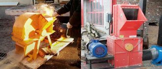
Garage hoist: drive manufacturing
You can make a hoist for lifting loads yourself. It is based on a brake lever that used to be on a truck. In a car, such a lever helps to supply the pads and reduce the gap between them.
To make a hoist with your own hands, you need to have skills in electric welding and turning.
The expansion knuckle shaft is cut to the required size using a lathe. The shaft is equipped with two washers. The entire structure is called a winding drum. One washer is equipped with a ring on the inside so that it does not interfere with the free passage of the cable.
How to make a drive:
Before manufacturing the lift, it is necessary to prepare drawings. The finished device can be used to lift and lower a centrifugal pump and other types of loads. As an alternative to this type of crane, you can make a hydraulic “Goose” crane.
To lift the engine and body in the garage, you will need a special mechanism. They are expensive, so you can save money by making them yourself. To do this, you must first familiarize yourself with the types of lifting mechanisms and their functionality. After choosing the type of mechanism, you need to start drawing up drawings and an assembly plan for the structure. For self-production, it is better to have turning skills and skills in assembling mechanisms.
Source
Drafting
To build a house you need a crane. Let's look at how to independently make a miniature crane design for lifting construction loads to a height. It is necessary to manufacture a mobile dismountable device.
First, a design for the manufacture of the apparatus is drawn up and calculated:
- The main part of the structure is the supporting frame. It is installed on wheels or permanently.
- The rotation unit of the unit is fixed to the running frame.
- The boom can be rotated thanks to the creation of electric or manual control.
- The unit can be disassembled into parts for ease of transportation.
- The crane will be stable thanks to the creation of a block of counterweights and steel cable stays.
- The load will be lifted using a block and a winch.
- You need to assemble a crane with your own hands.
Complex block system how to calculate power gain
If the system is designed in such a way that one simple pulley pulls another simple pulley, then this is already a complex system of blocks. To theoretically calculate the gain in strength, it is necessary to conditionally divide a complex chain hoist into simple ones and multiply the values of the gain from simple chain hoists. For example, if the system consists of 4 blocks, and the first conditional simple pulley has a gain of 3. It pulls the second simple two-block pulley, also with a gain of 3. The total force that will need to be applied will be 9 times less. It is the 4-block complex chain hoist that is most often used by rescuers.
Methods for attaching a rope to a lifting mechanism
When creating complex pulley blocks, there are often situations when a cable of the required length for attaching the moving block is not at hand.
Crane for gas blocks
Methods for attaching a cable using general-purpose rigging:
- Using a cord. Using a self-tightening knot, the cord is tied to the main cable. As the load is lifted, the grappling knot moves along the main rope, thereby allowing the height of the load to be increased.
- Using clamps. In the case of using a steel cable, it is not possible to use a cord, so it is necessary to use special clamps.
Blueprints
To make a crane, first of all, draw up a project diagram and drawings of the main components. Consider the manufacture of a manually operated crane structure. It would be possible to make a device powered by electricity, making it possible to move a load using a device on a long cable, as happens in factory designs. But then the complexity of manufacturing units increases, this will entail an increase in the cost of the finished product and an increase in the time for its creation. Therefore, we will focus on making a manual model.
Crane device
The cargo winch of my design is a worm gearbox with a 600 W electric drive, while the jib winch is a manual drive, organized on the same gearbox. Outriggers with screw stops are borrowed from construction supports. Drums for the winches were machined from rotors from electric motors, and suitable sizes were selected.
On the base of the mobile platform there are four wheels taken from the conveyor; thanks to them, the crane can be moved from one place to another without any problems, only if the outriggers of the crane are removed. This operation of removing and installing outriggers takes about five minutes. Therefore, the crane turns out to be quite mobile. But there is a small drawback: to move the crane, you need to lower the boom to zero, otherwise it becomes impossible to move the crane, since its balance is disturbed.
The boom itself has a length of 5 meters, the pipe was selected to be about 75 mm, and at the base of the boom itself there is a square profile made from two corners. There is also a portal for raising the boom, as well as a turning unit made from a hub from a truck. As a counterweight, a frame from a non-functioning machine was taken along with four tracks from a caterpillar mechanism. In this case, the brake in the winch is not provided, because it is not necessary. There is also no brake in the turn itself, due to the fact that the speeds are very low, and, therefore, there is practically no inertia.
The minimum thickness of the metal used in my crane is about 3 mm; a rectangular pipe with dimensions of 85 * 50 and 85 * 55 is used as an outrigger and base as a whole - this is a kind of remains of agricultural equipment. The base of the tower is made of channel 200. A powerful bearing is inserted into the hook cage, therefore, the hook is able to rotate regardless of the pulley, to avoid overlap or twisting of the cable itself.
The stop screws are 400mm long, allowing the crane to be installed on very uneven surfaces.
There is one small drawback related to the wheels. The thing is that the wheels used in this case, when moving on loose soil, simply bury themselves in it; on a hard compacted surface - everything is fine. This crane is considered disposable, that is, after completing the necessary work, it is disassembled for scrap or into a shelter until the next use. That is why this design has a low load capacity and not very outstanding strength.
The manufacturing time for such a crane will take about three days, taking into account the preparation of all the necessary components. In this case, the gearboxes were made from what came to hand; the gearboxes have the following gear ratios: 1/30 and 1/35. , output parameters on the shaft are 600 W, capacitor capacity is 80 microfarads. All installations without counterweights weigh up to 250 kg, the cost of such a design is 4,000 rubles. Mostly the components used are borrowed from other equipment; only the cables and bearings are new.
Such a crane can easily lift one and a half hundred kilograms of cargo; we have not yet been able to move more at home.
Technical characteristics of the result
A sample with length/height/width parameters of 228/380/160 millimeters, respectively, will be considered. The weight of the finished product will be approximately 1 kilogram. A wired remote control is used for control. Estimated assembly time if you have experience is about 6-8 hours. If it is not there, then it may take days, weeks, and with connivance even months for the manipulator arm to be assembled. In such cases, you should do it with your own hands only for your own interest. To move the components, commutator motors are used. With enough effort, you can make a device that will rotate 360 degrees. Also, for ease of work, in addition to standard tools like a soldering iron and solder, you need to stock up on:
- Long nose pliers.
- Side cutters.
- Phillips screwdriver.
- 4 D type batteries.
The remote control can be implemented using buttons and a microcontroller. If you want to make remote wireless control, you will also need an action control element in the manipulator hand. As additions, only devices (capacitors, resistors, transistors) will be needed that will allow the circuit to be stabilized and a current of the required magnitude to be transmitted through it at the right times.
Advantages and disadvantages
Over the course of many years of operation, the GAZ-53 has managed to establish itself as a simple and reliable truck that is quite easy to repair. This is precisely what can explain the fact that this car, long out of production, is still widely used today. Especially if it has a crane-manipulator installation, which allows you to expand the scope of use of the truck. The car can be repaired in the field; a wide range of spare parts for the GAZ-53 is offered on the market.
The following can be considered problematic components of GAZ-53 car manipulators:
In addition, the disadvantage of manipulators on the GAZ-53 chassis can be considered high fuel consumption, since the car uses a carburetor engine. This problem can be solved quite simply by installing the MMZ D-245 diesel unit. Reduced operating costs in case of switching to diesel fuel can quickly recoup the cost of replacing the engine. It should also be noted that the GAZ-53 car has a fairly low price on the secondary market, which makes such a manipulator a profitable purchase for limited finances.
Machine structure
The operating principle of a crane is based on the physics of simple mechanisms. The simplest version of the crane is a stick placed on a fulcrum in such a way that the free ends have different lengths. Now if you hang a load on a short lever, it will take less effort to lift it. The most common design is one that uses, in addition to levers, a system of blocks.
A do-it-yourself crane is an indisputable assistant in small-scale construction. When constructing a private house, the use of bulky industrial cranes is not required. The height of the houses rarely exceeds 2 floors, and the weight of the lifted load is 200 kilograms.
Crane diagram
Although there are many variations of lifting mechanisms, a classic crane consists of the following parts:
An arrow with a block attached to its end. Depending on its length, the height to which the load can be lifted is determined. Platform. The boom and counterweight are attached to it
It is the main part of the crane and is subject to significant loads. Therefore, when manufacturing the platform, it is important to pay special attention to its strength. Counterweight. Serves to stabilize the crane Determines the maximum weight of the load that the crane can lift
Stackable counterweight options are available to provide maximum stability. A guy wire connecting the boom and the counterweight. Allows you to adjust the tilt of the boom and move the load in both vertical and horizontal planes. Winch with cable. It is the lifting mechanism itself. The power of the winch determines how much weight the crane can lift. Stand with a rotating mechanism. It is necessary to turn the crane to the sides. The support cross, which is the base of the crane. Sets the stability of the entire structure. When manufacturing it, you should also pay attention to its strength.
terms of Use
To operate lifting mechanisms safely, certain rules must be followed.
Homemade Pioneer crane
These rules apply to any lifting device:
- The load capacity must not be exceeded. A load that is too heavy may damage the device.
- The base must be stable. Homemade lifting devices should be located on a previously prepared hard horizontal surface.
- In bad weather conditions, you should also refrain from working with the crane. Strong winds will throw the crane off balance, and poor visibility may make it difficult to see people under the boom.
- Before operating a crane or lifting device, it is necessary to conduct an external inspection to identify any malfunctions. If malfunctions are detected, operation of the crane is prohibited.
- It should be remembered that when working with the lift, you should not make sudden movements. The load must be lifted smoothly. And most importantly, do not stand under any lifted load.
How to use
The telescopic boom of the mechanism can be installed in several positions. The goose is maneuverable and can be controlled by 1 person. The equipment lifts quite heavy loads due to the installed jack; no additional accessories or devices for moving heavy loads are needed.
For full convenience of using your own garage, sometimes you need equipment for lifting heavy parts of the car. The best solution to this problem is a hydraulic crane. The unique structure allows you to rearrange small loads with little effort from the mechanic or car owner.
The hydraulic valve is made of durable metal and has a stable design. The main principle of the mechanism structure: stable support with low dead weight. This helps you lift loads of up to three tons with ease, but a maximum of two meters above the ground.
Garage crane is used for:
- removing the engine;
- lifting beams, bridges;
- movement of dimensional units.
The crane contains a hydraulic drive and operates through a system of communicating vessels. The method allows you to make the rise smooth.
Stationary
The stationary crane is installed in large car repair shops and is securely attached to a monolithic foundation. The mechanism has a boom with a rotating system and is equipped with a manual drive. Allows you to work on only one vehicle at a time.
Pioneer-500
The Pioneer-500 crane is a device for lifting loads up to 500 kg, which is installed both on the roof or ceiling and on the ground. When carrying out work on the roof, the maximum lifting height can reach 50 m, at ground level - up to 4.5 m. To repair flat roofing surfaces, the mechanism is lifted, installed and connected to an electrical network with a voltage of 220 V, 50 Hz via a flexible cable. For low-level work there is the possibility of attaching to the ground zero point.
The load is gradually lifted at a speed of 16.8 m/min, the platform rotates 360° with a rotating boom, moving the material to the desired location. The turning mechanism is manual, while the process is controlled, the lifting mechanism is electric.
The length of the solid boom for Pioneer-500 is 5200 mm, diameter - 102 mm. The dismountable device consists of 2 parts, each 2700 mm long, connected by bolts.
The chassis with a rotating frame has the following transport dimensions:
- length - 2450 mm;
- width - 1770 mm;
- height - 1325 mm.
Dimensional and weight characteristics of the crane:
- length - 4200 mm;
- width - 1700 mm;
- height - 5400 mm;
- weight without counterweight - 395 kg;
- total weight - 830 kg.
The mini crane can be easily dismantled, disassembled, moved manually to another place, assembled and re-installed.
Homemade mini crane based on a bottle jack
To make a hydraulic crane, we will use available materials that many people have in their garage.
We recommend: Stand for a small grinder made from an old bicycle
And even if you don’t find anything suitable at hand, everything you need can be purchased for pennies at a ferrous metal shop.
The lifting mechanism is useful both in the garage (for example, to raise and lower a car engine), and during construction work - for installing and dismantling various metal structures.
Basic materials that will be required to make a mini crane:
- profile pipe with a wall thickness of at least 3 mm;
- metal plate 5 mm thick;
- bottle jack (load capacity is at your discretion);
- swivel wheels;
- steel chain with hook.
Main stages of work
The first step is to make a support for the hydraulic mini crane. For this we need profile pipes.
Using a grinder, we cut pieces of suitable length and weld the base. After this, it will be necessary to weld a vertical stand to the support.
We weld two metal plates to its upper part, to which the lift boom is attached.
As a drive that will raise and lower the boom, we use a hydraulic jack with a lifting capacity of 12 tons (you can use another jack).
We weld a piece of profile pipe to the vertical post at an angle, which will serve as a stop for the jack.
We cut out a square plate from sheet metal and weld “ears” to it. Using a bolt and nuts, we attach the plate to the stop - this is a movable platform on which the sole of the jack will rest.
We weld a “glass” to the bottom of the boom for the support point of the jack piston. Next, we clean the welds with a grinder, after which we paint all the manufactured elements.
Assembling a load-lifting crane
We attach the bottle jack to the movable support platform on the vertical stand. We lower the boom so that the jack piston enters the “glass”.
We recommend: “Third hand” for welding small workpieces and parts
We install the retractable section of the telescopic boom, to the end of which we attach a chain with a crane hook.
This homemade lift is perfect for removing and then installing the engine from the car. It can also be used for other purposes - in the workshop and garage. The design is reliable and inexpensive.
For a step-by-step description of how to make a mini crane from a jack for a garage or workshop, watch the video.
Electric overhead crane trolley with a lifting capacity of 14 tons.
monster123
March 11, 2021
- 0
836
In this work, an electric overhead crane trolley with a lifting capacity of 14 tons was calculated and designed. Task: to design an electric overhead crane trolley with a lifting capacity of 14 tons. Mechanism: an electric overhead crane trolley. The crane operating mode is 4K. AC current. All gears are housed in closed housings. Calculation
Overhead crane drawings / Cranes
Operating principles of various elevator systems
Elevator lifts are divided into the following main types:
1) Electric
(electromechanical). 2) Hydraulic
.
3) Pneumatic
(airlift).
DIY elevator guides
To move the elevator, some kind of power device is required, the most convenient and practical power supply for which is electricity. Therefore, electric motors are part of the drive, regardless of its type. However, it is customary to call the elevators of the most common cable system electric, probably because in them the engine force is directly transmitted to the cables that move the cabin.
1. Electric elevator
, which we use in multi-storey buildings, works on the principle of a counterweight: the cabin is fixed on cables, at the other ends of which a counterweight is attached. The drive mechanism, located in the upper part of the elevator (engine room), having received an electrical signal from the panel buttons, sets the system in motion through a pulley wheel. Thanks to the counterweight, cabin inertia is reduced to a minimum, which ensures smooth movement and allows you to get by with a significantly lower power electric motor.
2. Hydraulic lift
works on the principle of a jack. The electric motor creates fluid pressure in the system, and the hydraulic cylinder pushes the cabin upward. No electricity is consumed during descent. This type of elevator has no counterweights and is silent. But due to the high pressure in the hydraulic system, it requires qualified maintenance and a powerful power plant.
3.
Pneumatic elevator cabin
works like a piston. To move the elevator upward, a vacuum of air is created in the air shaft above the cabin by powerful fans. As a result, increased pressure under the cabin pushes it upward. To descend, the pressure at the top and bottom of the cabin is equalized, and it smoothly goes down.
DIY pneumatic elevator
Now let’s ask ourselves the question: how to make an elevator with your own hands in the house, is it feasible for your hands and wallet?
A pneumatic elevator requires components that are almost impossible to make with your own hands. If you buy ready-made ones or order their production, the very idea of making an elevator with your own hands is lost. And the final cost will be rounded up to such a figure that purchasing and installing a ready-made airlift will cost less.
DIY hydraulic lift
Now - hydraulics
. Alas, it is no less difficult and expensive. A high-performance hydraulic pumping station will be required, and it is not cheap. Well, and most importantly – the hydraulic cylinder. Even raising an elevator car one floor requires significant extension of the rods. Dump trucks have similar units, but even if we decide to install such a hydraulic cylinder, we will be faced with another problem - lowering the cab. Automotive-type hydraulic cylinders fold under the weight of the heavy load bed of the dump truck. The weight of the elevator car will not be enough here. Combining various other ready-made mechanisms will be no less difficult and expensive.
The solution to the question of how to make an elevator yourself is obvious: make an electromechanical
Semi-gantry crane with lattice trusses, lifting capacity 25 tons
Ira Kokoulina
June 17, 2021
- 0
1 250
It includes a drawing of a semi-gantry crane with lattice trusses and calculations: calculation of the pulley (pulley block diagram, determination of the approximate and actual multiplicity of the pulley, determination of the rope tension force, pulley efficiency, selection of the rope is made according to the destructive load); selection of the main parameters of the drum (determination of the drum diameter,
Project drawings / Cranes / Gantry cranes
Industrial development[edit | edit code]
Electrical engineeringedit | edit code
Once a sufficient amount of latex, red dust (), copper, iron and tin has been found, you can begin to manufacture a generator - the first source of electrical energy, as well as the first consumer of electricity - an electric furnace (), which works almost twice as fast as a conventional one. To create an electric furnace you will need copper and red dust, because you will definitely need an electrical circuit.
IndustrialCraft² recommends that mined ore be first crushed in a crusher and only then smelted. Thus, from one block of ore you get 2 ingots, instead of one. Therefore, the sooner the crusher is manufactured, the better. There is also an ore washing machine and a thermal centrifuge, which allows you to wash even more resources from crushed ore. Likewise, it is recommended not to melt latex in a furnace to make rubber, but to use an extractor, as it squeezes more rubber out of the latex. The crusher, ore washing machine and extractor are also consumers of electricity.
Miner's affairs | edit code
At the initial stage of development in this mod, when a lot of iron has been accumulated, it is worth stocking up on stone pickaxes and one iron one and going to the mine (cave or canyon). It is recommended to stay in it for an hour or two of real time, mining a pile of , various stones (stone, coal, lapis lazuli, obsidian, diamonds) and red dust, so that later, during any complex or not very difficult crafting, you do not have to run into the mine for new portions of useful resources.
Subsequently, a mining laser and a drilling rig (used for automatic extraction of resources) will be very useful in mining.
Agricultureedit | edit code
The agricultural complex can be effectively used for the player’s life thanks to perches (which simplify farming) and plant selection. For example, Ferrium yields a small pile of iron dust as a harvest, and Aurelia yields a gold nugget. A mug of coffee is extremely useful, as it gives the player more energy, making him move faster. A coffee mug () is crafted from coffee fruits.
Small parts
To regulate the number of revolutions, you can use adapter wheels. They will make the movement of the manipulator hand smooth.
It is also necessary to ensure that the wires do not complicate its movement. It would be optimal to lay them inside the structure. You can do everything from the outside; this approach will save time, but can potentially lead to difficulties in moving individual components or the entire device. And now: how to make a manipulator?
How does a simple block design work?
Let's first consider a simple assembly pulley. It can be obtained by adding blocks to a support and a load. To get an odd mechanism, you need to secure the end of the rope to a moving point of the load, and to get an even one, we fasten the rope to a support. When adding a block, we get +2 to strength, and a moving point gives +1, respectively. For example, to get a pulley for a winch with a multiplicity of 2, you need to secure the end of the rope to a support and use one block that is attached to the load. And we will have an even type of device.
The operating principle of a chain hoist with a multiplicity of 3 looks different. Here the end of the rope is attached to the load, and two rollers are used, one of which we attach to the support, and the other to the load. This type of mechanism gives a gain in strength of 3 times, this is an odd option. To understand what the gain in strength will be, you can use a simple rule: how many ropes come from the load, this is our gain in strength. Typically, pulleys with a hook are used, on which, in fact, the load is attached; it is a mistake to think that it is just a block and a rope.
Pioneer-2000
The Pioneer-2000 crane is an improved version of the KP-1000 lift. After upgrading the model, the liftable load can reach 2 tons. This module is manufactured by the manufacturer to special order and is in demand in the construction of facade structures, when installing windows and sandwich panels.
Features of the 2-ton truck:
- equipped with electromagnetic hydraulic brake;
- electric drive for boom rotation;
- gearbox, power unit and winch with a 4-fold safety margin.
Taking into account the console reach, the maximum lifting capacity with double reeving of the rope is:
- with a reach of 4.6 m - 1500 kg;
- 4.4 m - 1700 kg;
- 4.1 m - 2000 kg.
Maximum lifting height of the hook mechanism:
- at reach 4.6 m - 4.3 m;
- 4.3 m - 4.5 m;
- 4.1 m - 4.65 m.
The maximum depth of lowering the hook is 100 m with a double safety margin of the rope.
Unit operating speed:
- with single reeving - 5.6 m/min;
- at double speed - 11.3 m/min.
The rotating part moves 360° around the axis. The turning radius reaches 3 m.
Structural weight - 1.5 tons.
Hydraulic garage crane drive
There are several types of hydraulic drive:
- with hydraulic cylinders;
- with hydraulic cylinders and manual winches.
When the operator increases the pressure level in the cylindrical block, the oil fluid acts on the piston part, pushing out the telescopic rod, at which time the boom equipment rises.
Based on the nature of the movement of the output link of the hydraulic power unit, the following types of drives are distinguished:
- Rotational movement. The design of such a mechanism includes a hydraulic motor equipped with a driven link with unlimited rotational movement.
- Forward movement. In this case, a hydraulic cylinder is used with a reciprocating movement of a driven type link (piston rod, plunger).
- Rotary movement. The crane mechanism is equipped with a rotary hydraulic motor, the driven link of which makes a reciprocating movement at an angle of less than 270°.
- Adjustable. In this case, the speed of the output type link can be adjusted by changing the crankshaft speed of the power unit, which activates the high pressure pump.
- With a closed circuit of working fluid circulation. This means that the fuel is returned to the suction hydraulic line of the pump mechanism. This drive is lightweight and provides high rotor speeds without the risk of air getting into the system.
Pioneer-750
The Pioneer-750 crane has technical indicators similar to the 500th model.
Module features:
- the mass of transported cargo is increased to 750 kg;
- lifting speed - 8.4 m/min;
- moving height - 45 m;
- manual rotation - using a special lever;
- load lifting mechanism - AIR100L4EU3 electric motor with a rated power of 4 kW and a rotation speed of 1410 rpm on 3-phase alternating current;
- control is carried out by a 220 V remote control;
- most units are made stationary, the booms are non-removable with a reach of 4.5 m;
- dimensions - 4.2x2.0x5.4 m;
- transport width - 2.18 m;
- transport length - 2.67 m;
- height - 1.35 m;
- weight - 1355 kg.
Scissor crane
The scissor crane is a simple and easy-to-use design. Due to their versatility and functionality, these devices are used in installation and construction work. They can also often be found in supermarkets and warehouses.
A scissor crane lifts tons of loads every day. This technique, in addition to the construction industry, is regularly used in the maintenance of advertising billboards, facade signs, and elevators.
Their main advantages include:
- performance;
- high load capacity;
- compact dimensions when folded;
- wide range of applications;
- maneuverability.
Their advantages also include autonomy - they can operate on batteries. In addition, cranes can be equipped with different types of drives:
- electrohydraulic;
- diesel;
- electrical;
- hydraulic.
Most often, models with electric drives are used in construction. They are affordable, environmentally friendly and easy to use.
There are a large number of variations of devices of this type, but almost all of them consist of:
- lifting device,
- mobile platform;
- equal-speed drive wheels.
To build a scissor crane yourself, you will need to make the base and platform of the apparatus from a channel. To make scissors you will need:
- two-section distributor;
- bushings;
- pump;
- hydraulic cylinder;
- I-beams.
A DIY scissor crane is capable of lifting loads weighing up to half a ton. This device is installed on the UAZ, and after operation it is removed. The basis of the structure will be a thick square bolted to the frame, and the retractable pores will be held on the car bumper.
Lift
Modern lifts are divided by type into:
- Foot. They are capable of lifting heavy loads weighing up to 2 tons to a height of 8 meters.
- Telescopic. Their advantages include: light weight and compactness. These devices are capable of lifting loads to a working height of up to 150 kg.
They, in turn, are divided into:
When choosing a lift, it is worth considering several factors: their dimensions, load capacity, scope of application.
To make a lift yourself, prepare materials and a preliminary drawing. To build it we will need:
- a winch, which can be made from a drum and a cable;
- pipes;
- electric drive
The advantages of construction hoists include:
- maneuverability;
- high load capacity;
- safety;
- ease of use.
How a simple block design works
The pulley system or pulley system has been known to mankind since ancient times. The classic system design consists of pulleys and cable. One pulley is called a block. Depending on the method of fastening, the pulley can be movable or fixed:
- Fixed block. It is attached to the support and plays the role of changing the direction of movement of the rope. Does not provide any gain in strength.
- Movable block. It is located on the side of the load and gives a gain in strength.
The principle of operation of a pulley block is similar to the principle of operation of a lever in the physics of simple mechanisms. The role of the lever in this case is played by the cable itself. In the case of a simple block of two pulleys, the movable pulley divides the rope into 2 parts and in order to lift the load the same distance, a rope twice as long will be required. The work of lifting the load is performed in the same volume. And the effort, due to the fact that the length of the rope has become twice as long, becomes half as much.
If there are more than 2 pulleys in the system, the gain in strength is approximately equal to the number of blocks. In the case of 3 blocks, the effort will be 3 times less, and 4 blocks will require only a quarter of the original effort.
Materials and tools
The most important thing when making a crane is to use high-quality tools and materials. This will guarantee that the structure will be strong and safe.
The cable should have minimal stretch; this will give a greater gain in strength when using a pulley system. The fittings used for tying must be taken only from metal. Plastic fittings cannot withstand heavy loads and break at the wrong time. To fasten individual parts of a homemade crane, you should choose high-strength hardware products.
If a winch is intended to be used, its lifting capacity should not be less than 500 kilograms. The best choice would be winches that can lift a load weighing 1 ton or more.
In conclusion, I would like to once again remind you of the need to observe safety precautions when working with lifting mechanisms. Also, regardless of whether the crane is purchased or made by yourself, you should inspect it before starting work.