Tables of the amount of copper in electric motors
Dimensional and weight characteristics of TM-2500
Types of marking of red KM capacitors with palladium and platinum silver for the purchase of radio components and precious scrap!!!
Tables for measuring the amount of copper in any electric motors
Main technical characteristics
| Transformer | TM-2500/10 | TM-2500/35 | |
| Rated power, kVA | 2500 | 2500 | |
| Rated higher voltage, kV | 6-10 | 35 | |
| Rated low voltage, kV | 6,3 | 6,3 | 10,5 |
| Winding connection diagram and group | Y/D-11 | Y/D-11 | |
| No-load losses, kW | 3,5 | 3,7 | |
| Short circuit loss, kW | 26 | 26,7 | |
| No-load current,% | 0,9 | 0,9 | |
| Short circuit voltage, % | 6,0 | 7,0 |
Table/calculator How much copper and aluminum is in a high-voltage power oil transformer TM-2500
Aluminum and copper alloys:
— 1st aluminum 600 kg.
- aluminum 3rd - 350 kg.
— copper alloys 303 kg..
—ferrous metal 6380 kg.-303 copper-350 alloy. 3rd grade - 60 kg. 1st grade alloy = 5127- 2130 oil = 2997 metal
- transformer oil 2130 kg.
- iron 2997 kg x 22 rubles = 65,934 rubles
- transformer oil 2130 x 25 rubles = 53,250 rubles
- aluminum 3rd - 350 kg. x 110 rub. =38,500 rubles
— grade 1 aluminum 600 kg. x 170 rubles = 102,000 rubles
— electrical copper type (gloss) 303 kg.. for 630 rub. =190,890 rubles.
Types of marking of red KM capacitors with palladium and platinum silver for the purchase of radio components and precious scrap!!!
Tables for measuring the amount of copper in any electric motors
All of the KM capacitors listed below have inside their ceramic housing such precious metals as platinum, palladium and silver and, accordingly, are valued in the market for valuable radio components and are bought up not only by buyers of radio markets and precious metals, but also by those who are involved in the refining and chemical extraction of platinum and gold , palladium and silver, as well as other rare earth metals.
Red KM capacitors types and markings for sorting and handing them over to buyers and not making mistakes. Different groups have different prices and, accordingly, they have different platinum and palladium contents, i.e. precious metals.
Well, let's look at the general group of red capacitors ; they are distinguished by the numbers 3,4,5,6 and are also yellow , but of course they are predominantly red with different color shades. Conventionally, the so-called square ones are dark orange in color . They are all in the photo, for example the number 6 is at the beginning of 65F/1M5 and so on
Ceramic KM capacitors belong to monolithic KM capacitors (general group 3, 4, 5, 6) - these are low-voltage electrical energy storage devices that are necessary to ensure efficient and correct operation of frequency driving circuits, feedback circuits (positive or negative), and block filters nutrition. Approximately, the presented radio components began to be produced for the first time since 1977 at the Vitebsk Production Association "Monolith".
Welding rectifier
Usage: the device relates to electrical engineering, in particular to welding technology. The essence of the invention: the device contains a single-phase transformer with a two-rod magnetic core. On one of its rods there is a network winding and a sectioned first part of the valve winding, and the invention relates to electrical engineering, in particular to welding technology. The purpose of the invention is to improve the basic technical characteristics of the device by expanding the range of regulation of welding currents and simplifying it by eliminating the current-limiting choke and reducing the number of branches of the valve winding. The drawing shows a block diagram of the proposed welding rectifier device. The device contains a single-phase transformer 1 with a double-rod magnet - the second part of the valve winding, made with branches. The plug-in type switch is made with at least four pairs of terminals and a contactor. The first input of the rectifier is connected to the end of the first part of the valve winding, and the tap of the second part of the valve winding is connected to the first terminal of the first pair of terminals. The first terminal of the second pair of terminals is connected to the first terminal of the third pair of terminals. The beginning of the first of the sections of the first part of the valve winding is connected to the first terminals of the second and third pairs of terminals. The beginning of the last of the sections is connected to the second input of the rectifier and simultaneously to the second terminal of the second pair of terminals and to the first terminal of the fourth pair of terminals. The second terminal of the fourth pair of terminals is connected to the beginning of the second part of the valve winding. The end of the second part of the valve winding is connected to the first input of the rectifier. The second terminals of the first and third pairs of terminals are connected to each other and to the end of the last section of the first part of the valve winding. 1 ill. a conductor, on one of the rods of which there is a network winding 2 and the first part of the valve winding 3, and on the second - the second part of the valve winding 4, a plug-in type switch 5 with four pairs of terminals 6,7,8,9 with terminals 10-11, 12 -13, 14-15 and 16-17, respectively, and a contactor 18, and a rectifier 19 with the first 20 and second 21 inputs. The second part of the valve winding 4 is made with branches. Its beginning 22 is connected to the second terminal 17 of the fourth pair of terminals 9, branch 23 is connected to the first terminal 10 of the first pair of terminals 6, and the end 24 is connected to the first input 20 indirectly. Yo Chyu o 00 3 SOVIET UNION
SOCIALIST
REPUBLIC (i)z V 23 K 9/00
STATE PATENT
USSR DEPARTMENT (USSR STATE PATENT) DESCRIPTION OF THE INVENTION
FOR THE AUTHOR'S CERTIFICATE (21) 4882968/08 (22) 10/11/90 (46) 02/23/93. Bull. N 7 (71) Organization of tenants of the Scientific and Production Association “Kontactor” (72) P.F.Aíäðèàíoâ, V.V. Kochetkov and
A.F. Kuzmin (56) Copyright certificate of the USSR. M 1460745, class. N 01 R 31/06, 1986.
Multipurpose power supply SP31125/220 UZ MIP, TU16-565.001-83, instruction manual.
Welding rectifier type VD0801UZ “Universal”, TU16-435.124-86, Operating manual. (54) WELDING RECTIFIER (57) Use: the device relates to electrical engineering, in particular to welding technology. The essence of the invention: the device contains a diaphase transformer with a two-rod magnetic circuit. On one of its rods there is a network winding and the first part of the valve winding is sectioned, and on the second part the invention relates to electrical engineering, in particular to welding technology. The purpose of the invention is to improve the basic technical characteristics of the device by expanding the range of regulation of welding currents and simplifying it without exception current-limiting choke and reducing the number of branches of the valve winding.
The drawing shows a block diagram of the proposed welding rectifier device. The device contains a single-phase transformer 1 with a two-rod magnet! “1 796370 A1 rum” is the second part of the valve winding made with branches. The plug-in type switch is made with at least four pairs of terminals and a contactor.
The first input of the rectifier is connected to the end of the first part of the valve winding, and the tap of the second part of the valve winding is connected to the first terminal of the first pair of terminals, the First terminal of the second pair of terminals is connected to the first terminal of the third pair of terminals. The beginning of the first of the sections of the first part of the valve winding is connected to the first terminals of the second and third pairs of terminals. The beginning of the last of the sections is connected to the second input of the rectifier and simultaneously to the second terminal of the second pair of terminals and to the first terminal of the fourth pair of terminals. The second terminal of the fourth pair of terminals is connected to the beginning of the second part of the valve winding. The end of the second part of the valve winding is connected to the first input of the rectifier. The second terminals of the first and third pairs of terminals are connected to each other and to the end of the last section of the first part of the valve winding. 1 ill. a conductor, on one of the rods of which there is a network winding 2 and the first part of the valve winding 3, and on the second - the second part of the valve winding 4, a plug-in type switch 5 with four pairs of terminals 6,7,8,9 with terminals 10 - 11, 12-13, 14 - 15 and 16 - 17, respectively, and a contactor 18, and a rectifier 19 with the first 20 and second 21 inputs. The second part of the valve winding 4 is made with branches.
Its beginning 22 is connected to the second terminal
17 fourth pair of terminals 9, branch 23 - with the first terminal 10 of the first pair of terminals
6. and the end 24 - with the first input 20 of the rectifier 19. The first part of the valve winding 3 is sectioned, Beginning
25 of the last section is connected to the second input 21 of the rectifier 19 and simultaneously with the second terminal 13 of the second pair of terminals 7 and with the first terminal 16 of the fourth pair of terminals 9. The end of the first section 26 is connected to the first input 20 of the rectifier 19.
The beginning of the first section 27 is connected to the first terminals 12 and 14 of the second 7 and third
8 pairs of terminals; Second terminals 11 and 15 first
6 and the third 8 riap terminals are connected to each other and to the end 28 of the last section of the first part of valve winding 3. When the contactors 18 of terminals 12 and 13 are closed, the device operates in battery charging mode, when terminals 14 and 15 are closed in the starter mode of the car engine, when closing terminals 10 and 11 - in the welding mode with the maximum value of the welding current, when closing terminals 16 and 17 - in the welding mode with the minimum value of the welding current, As can be seen from the diagram, to obtain the maximum value of the welding current, series-connected certain shares of the first and second parts of the valve winding, which ensures a given rigidity of the external characteristic, and to obtain the minimum value of the welding current, only the second part of the valve winding is used, which allows for open-circuit voltage at the same voltage. provide a greater slope of the external characteristic and thereby expand the limits of welding current regulation. Thus, if the known device provides a ratio of maximum to minimum welding current equal to three, then in the proposed device with the same overall power of the transformer and an equal value of the maximum current, a ratio of maximum to minimum current equal to four is provided. This allows you to eliminate the current-limiting choke from the device, thereby reducing its weight and dimensions. In the known device, the first part of the valve winding must have at least three branches, and in the proposed device the first part of the valve winding can be made
: made of two sections, which simplifies the design of the transformer.
Thus, the positive effect provided by the proposed device is to improve the basic technical characteristics and simplify the design.
The novelty of the proposal is that the first part of the valve winding is made sectional, the beginning of the first of the sections is connected to the first terminals of the second and third pairs of terminals, the beginning of the last of the sections is connected to the second input of the rectifier, and simultaneously with the second terminal of the second pair of terminals and with the first terminal of the fourth pair of terminals. the second terminal of which is connected to the beginning of the second part of the valve winding, the end of the second part
15 of the valve winding is connected to the first input of the rectifier, and the second terminals of the first and third pairs of terminals are connected to each other and to the end of the last section of the first part of the valve winding.
Claim
Welding rectifier containing a single-phase transformer with a two-rod magnetic core, on one of the rods of which there is a network winding and the first part of the valve winding, and on the second - a second part of the valve winding made with branches, a plug-in type switch with at least four pairs of terminals and a contactor , and a rectifier, wherein the first input of the rectifier is connected to the end of the first part of the valve winding, the branch of the second part of the valve winding is connected to the first
35 terminal of the first pair of terminals, and the first terminal of the second pair of terminals is connected to the first terminal of the third pair of terminals, differing in that, in order to improve the basic technical characteristics and simplify the design, the first part of the valve winding is made sectional, the beginning of the first of sections connected to the first terminals of the second and third pairs of terminals, the beginning of the last IE
45 sections are connected to the second input of the rectifier and simultaneously to the second terminal of the second pair of terminals and to the first terminal of the quarter pair of terminals, the second terminal of which is connected to the beginning of the second part
50 valve winding, the end of the second part of the valve winding is connected to the first input of the rectifier, and the second terminals of the first and third pairs of terminals are connected to each other and to the end of the last section of the first
55 parts of valve winding, 179b 370
Compiled by A. Kuzmin
Techred M. Morgenthal Proofreader I. Shmakova
Editor
Production and publishing plant "Patent", Uzhgorod, Gagarin St., 101
Order 61g Circulation Subscription
VNIIPI of the State Committee for Inventions and Discoveries under the State Committee for Science and Technology of the USSR
113035, Moscow, Zh-35, Raushskaya embankment, 4/5
Technical parameters of KM capacitors
The average static mass of such red KM capacitors is from 0.5 grams to 3 grams. Rated operating voltage: from 50 - 250 V. Standard values of electrical capacitance can be within 1.2 pF / 2.2 μF. Permissible deviations of the capacity values indicated in the marking: 2 – 80%. this information can appear on the body of the red KM capacitor in abbreviated form or in the form of a record.
In the photo, the number 6, for example, is at the beginning of 65F/1M5.
Well, the next group with numbers 1 or 2 is light orange (1BAD Fm 68 or 2BB4F2m2 ), the marking 1 i 2 is at the beginning of the inscription. Small ones are removed or bitten off from radio boards from Soviet televisions from the USSR era, six to eight program television receivers. Low-voltage capacitors KM groups 1, 2 (orange) or conditionally orange (COLOR MAY BURN OUT) are characterized by high stability, minimal losses in low-frequency and high-frequency circuits. These radioelements are found in various electronic equipment, for example, in measuring equipment (voltmeters), medical equipment (ultrasonic irradiation devices, ultrasound), and approximately the same medical and household purposes.
The limits of their operating voltage, depending on the modification of KM capacitors : 25 - 250 V. Possible electrical capacitance, depending on the modification of KM capacitors : 1.2 nF - 2.2 μF. Operating temperature range, depending on the modification of the capacitors: from -65˚С to +155˚С.
The KM group with numbers 1 or 2 is light orange (1BAD Fm 68 or 2BB4F2m2), the marking 1 and 2 is at the beginning of the inscription.
KM capacitors 6N90, 6V, 6M1500 (orange)
Thermally stable capacitors KM 6N90 M68, 1M0 are used in various electronic equipment for special, medical, research and household purposes. The body of each element is painted orange and has unidirectional contacts. presented by KM began to be manufactured for the first time at the Vitebsk Production Association "Monolit" in 1977.
Another group of red KM capacitors is 6H90 80-85 about the year of manufacture and
KM 6N90, 6V, 6M1500 (orange)
Thermally stable capacitors KM 6N90 M68, 1M0 are used in various electronic equipment for special, medical, research, and household purposes. The body of each element is painted orange and has unidirectional contacts. The presented capacitors were first manufactured at the Vitebsk Production Association "Monolit" in 1977.
Another group of red KM capacitors is 6H90 80-85, about the year of manufacture and terracotta color ( we define it as red 6V15nM and M 1500
Defined as red 6V15nM and M 1500
Capacitor KM 6F 1m0 (orange)
Next comes our group of KM ceramic capacitors attached to the name of conventionally red 6F 1MO of bright and pale orange color in a conventionally square case .
Capacitors KM 6F 1m0 accumulate electric charge (energy), which allows them to be effectively used to smooth out ripples of rectified voltage in power supplies, as well as to separate the constant and variable components of the useful signal during its cascade conversion in one radio device. The production of KM capacitors of this type began in 1977 at the Vitebsk Production Association "Monolit". The body of the element looks like a small pillow and is painted orange, while the solder pins are located on one side of the corner part of the capacitor ( at the very end of the corner of the KM capacitor).
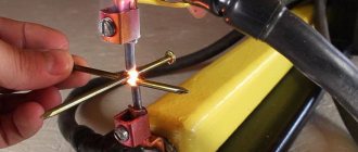
Body shop in the yard: test of a Soviet welding machine powered from the on-board network
It's been a while since we updated the exposition of our editorial museum of Soviet retro automobile accessories and gadgets! A new addition, another “time capsule” found in garage attics, was a unique device - an automobile welding machine!
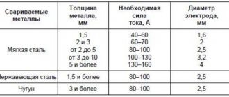
It was a three-kilogram metal box of desperate red color with dimensions of 260x190x110 mm, with two powerful bolt terminals for connecting welding wires on the front panel. Using this device, it was possible to weld with an electrode with a diameter of up to 3 millimeters in the “2.5 minutes welding - 2.5 minutes rest” mode.
1 / 2
2 / 2
According to the fashion of the naive era, when every village general store tried to call itself a “shop” and “market,” the inscription on the device is duplicated in English. On the front panel of the welding machine there is a large word “AVTOVAZ” and the familiar logo of the Togliatti “ladya”. However, of course, this device was not produced by the car plant itself, but by its subsidiary - PTO VAZ, founded in 1972, six years after the launch of the main one, it stood for "Production of Technological Equipment" - this auxiliary enterprise made metalworking machines, painting machines for the main Zhiguli conveyor and other technological equipment, which was supplied, among other things, to other automobile plants of the USSR.
During the era of perestroika, all state-owned enterprises were voluntarily and compulsorily focused on expanding the range towards “consumer products”, within the framework of which the ASP-1 automobile welding machine was born at the VAZ technical workshop - for citizens and, as they would say now, for “micro-businesses” – cooperators working in the field of small services to the population..
The huge red light bulb on the top cover looks like some kind of handicraft modification - strange and absurd... However, this is a standard design element, the role of which is reflected in the instructions. It burns brightly until the electric arc on the electrode is lit, indicating that the battery is charging, and goes out when welding begins.
Why, instead of such a hefty “flashlight”, an LED or at least a miniature incandescent indicator light was not used is unclear...
The weight of the device is stamped on the nameplate – “5 kg”. However, the device itself weighs about three kilos; five is a mass with welding wires, an electrode holder and a mass “crocodile”.
Those familiar with electronics may think that under the ASP-1 cover there is a pulse converter-inverter, as inside most modern inverter welding machines operating on a 220 volt network... But do not forget - this is the very beginning of the decade of the 90s, when most people continued to call their country, according to the habit of the USSR, all cars had carburetors, and computers were found only in large research institutes... Powerful pulse technology, as well as the corresponding powerful power transistors and diodes, were rarely found in household devices at that time, even abroad - not like in yesterday “ scoop." So everything was much easier!
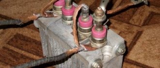
No voltage conversions occurred inside the welder - of all the electronics, it contained only two powerful thyristors. In order to be able to cook from the electrical system of a passenger car, ASP-1 essentially did only three simple things:
- Raised the voltage on the generator, taking over the role of the standard relay regulator.
- I connected the battery in parallel with the generator if there was not enough current.
- It automatically switched to charging the battery as soon as the welder tore the electrode off the part and stopped working.
That is, in essence, the welding machine was 90% a car generator, the positive terminal of which was directly connected to the welding electrode. The machine’s engine, of course, had to be running during welding, and to ensure maximum output current, the instructions prescribed turning the crankshaft up to 2500 rpm with the help of a choke or an assistant pressing the pedal. And the role of ASP-1 was “auxiliary and switching”, so to speak...
Welding using ASP-1 is quite simple. The engine of the machine is started, the choke is set to 2500 engine revolutions, a powerful crocodile terminal is connected to the part being welded, an electrode is inserted into the handle-holder, a shield or mask is lowered over the eyes, and the process begins.
But if you thought that before this you just need to connect the power supply of the device with alligator clips to the battery, then you are seriously mistaken! This is a harsh Soviet Zhiguli gadget, and not a modern lithium-ion booster-power bank that any blonde can handle! Connecting ASP-1 required serious intervention in the electrical wiring under the hood.
Actually, the first point of the installation process required fixing the welding machine permanently under the hood of the “classic” or “nine”. Yes, yes, it was assumed that the welder would become a permanent “under-hood resident”, like a carburetor or a gas pump, because its electrical integration into the car’s electrical system had a number of features. It was necessary to disconnect the power positive output wire from the generator and connect it to the welding machine. Thus, the welder was connected between the generator and the battery. Then it was prescribed to disconnect the relay-regulator from the generator, the role of which was taken over by the welding machine. In short, to connect welding, the car owner made a good dozen switchings in the electrical wiring of the car - he disconnected something, and connected something, on the contrary, with jumpers. Everything necessary for this, including wiring, terminals and all sorts of casings, was included with the welding machine.
At first glance, it may seem that even short-term use of your own car as a welding installation required a long fiddling under the hood, and then similar fiddling in the reverse order to return the wiring to its previous state in order to drive away. But no!
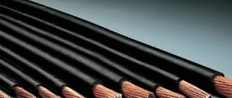
It’s no secret that Soviet engineers, when developing consumer goods, often spartan-style ignored issues of basic comfort in use, but not in this case! The ASP-1 kit included a special wiring pigtail with an 8-pin connector, which was connected to the vehicle's electrical wiring. When you needed to cook, you plugged the plug from the welding machine into this connector, and when you had to travel, you plugged a special shorting block. The block was a mating part of the same connector with jumpers in a certain order, and, when inserted instead of welding, it completely restored the car's factory wiring to normal!
So what is ASP-1? An ingenious development, indispensable in a number of extreme cases, or a strange miscarriage of the clumsy industry of the era of the emerging market economy? Why are similar gadgets not produced today, since many people still have a periodic need for simple and easy mobile welding where there is no outlet?
Let's be honest: such a device is still a typical product of the “time of troubles”, such as a kitchen ladle made of tank armored steel from Uralvagonzavod... The reliability of the device itself was extremely high, but the stator windings and puny Soviet rectifier diodes of Zhiguli and Moskvich generators worked with welding in almost short-time mode short circuits, at the current limit, and even with increased voltage! The battery, which was also constantly included in the welding process, lost its life due to high discharge and charge currents.
ASP-1 welding was developed and sold in the era of carburetor cars with a minimum of electronics, and, oddly enough, was somewhat “ahead of its time,” because today even many budget cars have 120-160 ampere generators with much more powerful diodes, which since they would be much better suited for use in conjunction with an electrode and a mask... But on a modern machine, saturated with electronics, such an introduction into the electrical system is extremely dangerous, and often fundamentally unacceptable, which is why analogues of the ASP-1 are not produced or sold these days. “The Red Box” has become a collectible curiosity...
Main technical characteristics of KM cushion-type capacitors.
Rated electrical capacitance: 1 µF. Rated operating voltage: 50 V. Operating temperature limits: -65˚С and +120˚С. Loss tangent range: 0.0012 – 0.035.
KM capacitors 6N90 M68, 1M0 (orange)
Another similar group of KM H90/1MO and rare H90 1M5 - these capacitors are more pot-bellied and massive in comparison with other KM capacitors, they are simply large, do not forget about the years of production, which are in the lowest case of the marking inscription... Conventionally square, solder ends on one side. Accepted as H90 with a nominal value of 1mO Capacitors KM 6N90 2M2 can be found in various radio circuits for separating the alternating and direct components of useful signals during their transmission to adjacent stages, as well as for effectively smoothing out rectified voltage ripples. Due to their properties, the presented elements are used in communication systems (telephones, walkie-talkies, etc.), in measuring, scientific, industrial equipment, and in uninterruptible power supplies.
Rules for choosing power tools
First, it’s worth understanding what types of power tools there are:
- professional models - for example, brands Makita, Bosch (blue), Kress, Stihl, Hitachi, etc.;
- amateur options - manufacturers Bosch (in green), Black&Decker, Skil, Ferm, Einhell, etc.
Professional tools are designed to last: you can work with them all day long. They are thought out to the smallest detail, and the construction is very durable. But you should understand that the price of such models is high. If you need an electric scythe or a welding machine for home use, it is better to go with amateur options.
Decide on other parameters:
- power supply (battery or mains) - the former are mobile, but it should be remembered that batteries often fail;
- case material - it should be high-quality and reliable plastic that will serve you for many years.
Also find out about additional product features.