Home / Welding technique
Back
Reading time: 4 min
1
6426
First, let's figure out what it is. If, when using electric arc welding, we also turn on short electric pulse signals, then we will get pulsed welding.
In this case, the main thing is not to draw a parallel of this type with spot welding.
Pulse spot welding and pulsed arc welding are completely different methods of welding metal parts.
- Let's analyze the algorithm for collecting pulsed welding Converter
- Control mechanism
- Adapter
Let's analyze the pulse welding collection algorithm
Converter
To begin with, it is necessary to consider the process of assembling a pulse converter. It is accordingly designated as the power element of the welding unit.
The diagram shows the transducer assembly model.
In technical literature and reference books you can find information on the components that are included with the converter.
Control mechanism
In this figure you can see a clear and understandable control diagram, as well as elements of the diagram, which shows the process of starting the electric unit.
Adapter
A descriptive representation of the pulse adapter is shown in the accompanying diagram.
“Soft Launch” is located here.
How does the conversion happen?
Electrical circuits of inverter devices from different manufacturers may differ in small details, but they all work according to the same algorithm. The main task of embedded electronics in all cases comes down to the following:
- provide rectification of the input mains voltage;
- convert (invert) it into a pulse signal of relatively high frequency;
- reduce the level of the received pulse signal to the required value and rectify it again at the output of the device.
The main purpose of this chain is to obtain a constant current of the magnitude necessary to maintain the welding process. Moreover, this must be done in such a way that the parts used in the circuit make it possible to reduce the dimensions and weight of the entire device as a whole.
Since the electronic converter consists of semiconductor parts, the task assigned to the designers is solved without any problems. The inverter is always significantly smaller in size than a conventional transformer current converter.
However, the welding inverter circuit is much more complicated, and it is almost impossible to assemble it yourself from scratch. You can only use ready-made parts, combining them into a common structure.
Another advantage of the inverter is the ability to electronically regulate the amplitude value of the current. This allows you to expand the capabilities of the device, weld metal of different thicknesses, including welding fairly thin parts. Moreover, this can be done without mechanical regulators, which are noticeably inferior in reliability to their electronic counterparts.
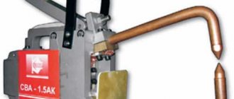
Assembled device
Just look at the figure below to have a simple idea of the appearance of this type of welding.
The body is also attached to a frame with airflow, a control adapter (it is an integral part of the body), and a plug for welding current.
The electrical fuse and power adapter must also be located on the housing.
general information
Argon arc welding is in many ways very similar to manual arc welding, only argon shielding gas and filler wire are additionally used. At the same time, a non-consumable tungsten electrode is used. The electrode helps ignite the arc and the wire forms the seam. In the world this welding technology is called TIG.
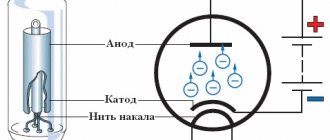
The essence of argon arc welding is simple. First, the torch supplies argon to the welding zone. A second after the gas is supplied, the welding arc is ignited. To ignite an arc, you need to bring a torch with an electrode inside to the metal and press the switch. But why is the arc ignited? After all, there is no reason for this.
An oscillator solves this problem. It ionizes the gas and thereby allows the arc to ignite in argon vapor.
Practice of use
Devices assembled as stated in the instructions work for a long time. Welding joints are quite strong.
A homemade pulse welder is only suitable for household use, but it is not suitable for professional work. The costly part of assembling such a welder will not leave any owner indifferent.
The voltage required for the operation of such a device should be within 220 V. But sometimes there may be voltage failures, especially if the work is carried out in a country house.
The welding inverter was developed on a popular forum by a person under the nickname Timval, the thread is still very active. This particular scheme is popular because of its simplicity. My version of the welding inverter is designed for a current of only 100 amperes, this is not enough, but for my tasks it is no longer needed.
The circuit is a single-cycle forward inverter with just one IGBT transistor IRG4PC50KD .
The inverter consists of several parts:
- Input rectifier with storage capacitors and soft start system;
- Control systems with a driver based on a complementary pair of composite transistors of medium power;
- The power part consists of an IGBT transistor and a transformer;
- The output part, consisting of a choke with a rectifier.
KBPC3510 input diode bridge
and is smoothed out by capacious electrolytes.
It is important to note that at the initial moment of time the power is not supplied directly, but through the ballast resistor R12, this is necessary for smooth charging of the capacitors, otherwise the surge current can damage the input diode bridge and knock out the machines.
At the same time, power from the capacitors through another ballast resistor R11 is supplied to the power line of the PWM chip.
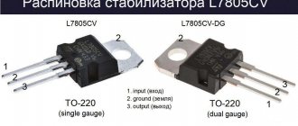
The heart of the circuit is the UC3844 ,
which operates at a frequency of about 30 kHz, the signal from the microcircuit first goes to the driver, made on transistors VT2 and VT3, and then to the power transistor VT4.
The voltage on the capacitors increases, so does the power supply to the microcircuit, and as soon as it reaches the threshold value, for the UC3844 it is about 16 volts, the microcircuit will begin to generate control pulses, which will lead to the start of the entire inverter.
Voltage will appear in the secondary windings of the transformer, this will cause the power relay K1 to operate and close the ballast resistor R12 with its contacts, and the mains voltage will be supplied directly to the circuit. The planned launch lasts only a couple of seconds. After a smooth start, the inverter will operate normally. The output voltage of the inverter is about 60 volts, this is enough for normal arc ignition.
If you rotate the current limiting regulator (resistor R3) during welding, the feedback system will immediately work (a circuit consisting of a current transformer CT, diodes VD2-VD4, resistors R5 and R7, capacitor C4).
The current transformer is wound on a small toroidal ferrite core; it has two windings, the primary - just one turn and the secondary.
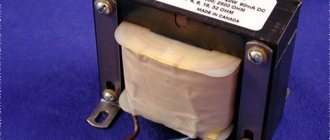
The power transformer is made on an EPCOS E55/28/25 ferrite core No. 87.
The core was without a frame, so I had to make it myself from mteklotextolite.
The transformer has 4 windings:
- network;
- secondary power;
- fixing;
- self-powering winding for the control system.
In my version, the self-powering winding is not used; instead, a small 24-volt switching power supply with a current of 1-1.5 Amperes is used.
The beginnings of all windings in the diagram are indicated by dots; I advise you to mark the beginning of the winding, for example, by putting red heat shrink on the winding, so that later you don’t have to guess where the beginnings and where the ends of the windings are.
At the very beginning, the network winding is wound, but not completely, but in parts. In my case, a wire with a diameter of 1.20 mm and 25 turns was used to wind this winding. The wire must be laid evenly, turn to turn.
The winding is then insulated, but before that it is filled with epoxy resin. The resin will fill all voids. Because Due to strong magnetic fields, vibrations will form in the transformer and the wire insulation may suffer over time, and with resin the winding will be completely motionless.
We put insulation with Kapton heat-resistant tape and wind the rest of the primary winding. The number of turns, wire and winding direction are the same.
Again we fill everything with resin and put insulation on top. Later, on the board, the ends of these windings are connected in parallel.
Then we wind the fixing winding, the wire diameter is 0.5 mm. The number of turns is 25-26, that is, the same as in the case of the primary winding. This winding is wound so that the wire falls between the turns of the primary winding. The fixing winding is evenly stretched throughout the frame. We do the same with this winding, resin, insulation. By the way, earlier I installed insulation in 2-3 layers, but after winding the fixing winding, more serious insulation is needed, 4-5 layers.
And finally, the power winding, the most labor-intensive. It can be wound with a copper busbar or, even better, with tape. Litz wire works most effectively - a wire that consists of a large number of parallel thin wires insulated from each other; such winding is done to minimize the influence of the skin effect. But at frequencies of 30 kHz, this effect is not so noticeable, so if you really want, you can take a couple of copper wires of large diameter, but such a wire is very difficult to lay, so I chose Litz wire.
The winding consists of 100 parallel strands of 0.5 mm wire. We twist the whole thing with a drill and cover it with additional insulation, again Kapton tape.
The number of turns is only 9, according to calculations this is enough for the inverter’s no-load voltage to be around 60 volts. After winding, it should also be filled with resin.
The circuit is single-ended and a non-magnetic gap is needed between the halves of the core. In my case, to obtain the required clearance, gaskets were installed under all the cores, a regular receipt from an ATM.
Next, the transformer is assembled, the core halves are securely pulled together, you can even glue them.
Current transformer. Ferrite ring, permeability can be from 1500 to 3000. The dimensions of my ring are R18x8x6. It is important that it be ferrite; similar rings can be found in some switching power supplies; they are located at the input as a choke and usually have two windings. Yellow-white, green-blue rings will not work, the material is different.
First, the core is insulated, in my case with Captnon tape, then the secondary winding is wound. The wire is in varnish insulation, the diameter can be from 0.25 to 0.5 mm. The number of turns in my case is 76.
Next, the winding needs to be insulated; you can simply fill it with epoxy resin. The primary winding is one turn of two parallel strands of 1.20 mm wire going to the power transformer.
The output rectifier is classic for this topology. There are two diodes, a direct one and a short-circuiting one, and the short-circuiting one needs a more powerful one, but you don’t have to worry about it and just plug in two diodes of the 150EBU04 type for 150 amperes with a reverse voltage of 400 volts. Diodes from this line are usually used in welding inverters. Ultra fast diodes are a must. You can use STTH20003 diode assemblies.
Each case contains two ultra-fast diodes independent of each other, each rated at 100 Amps with a reverse voltage of 300 volts. They are even better than 150EBU04 because... their substrate area is much larger and thicker. The connection is screw, which is very convenient.
Throttle. Here everything is not so simple and in fact the choke is quite critical. The greater its inductance, the better the arc will ignite even at low currents. According to the circuit, the inductor is 40 µH, it will be enough, but I got reliable arc ignition at currents of 30 amperes and, in principle, this will be enough.
Honestly, I tried different materials for the inductor - alsifer, unknown rings that are apparently used as a filter in frequency converters, and finally a core made from transformer plates.
The best solution is to use powdered iron cores, they are specially designed to work as a choke, but the ring needs a decent size, and they are not so easy to find and they cost a lot of money. As a result, on the advice of my colleague Timur, who had previously assembled this welder, my choice settled on a package of iron transformer plates.
The trick is that it is virtually impossible to drive the core into saturation, that is, you can increase the inductance and get reliable ignition of the arc at welding currents of at least 5 amperes, I understand that no one cooks at such currents, but still.
The package was assembled from what was available, and in the end the core turned out to have dimensions of 86x30x17mm. I wrapped the plates with Kapton tape, then paper tape and wound the winding. The winding is unfortunately aluminum, but copper is better, but aluminum was available. The winding is wound in three rows, each row has 10-12 turns. After winding each row, the winding was varnished in several layers and insulated with fabric. The final inductance of the inductor is about 80 μH. The disadvantage of such a choke is its large size and weight, but in my case everything turned out quite compact, and I even managed to fix it on the board. The inductor terminals were crimped with tinned copper terminals, the key word is tinned, otherwise such a connection will not work for a long time, it will overheat and oxidize.
Entrance part. The diode bridge was taken ready-made, assembled KBPC3510, bridge rated at 35 amperes, reverse voltage 1000 volts, installed on a radiator.
The power relay in the soft start circuit with a 24 volt coil is designed for a current of 15-30 real amperes; if you plan to use a welder for currents of more than 120 amperes, then it is advisable to use a 30 ampere relay.
Input electrolytic capacitors are 450 volts, in my case there are 2 pieces of 470 μF each, it is advisable to install three, it will not be worse. Select capacitors from a good manufacturer with the lowest possible internal resistance.
It is advisable to take a limiting resistor at the input of 10 watts, a resistance of 10 to 30 ohms.
Diodes VD7, VD8 and VD9 in the converter circuit are needed ultra fast, precisely for the current and voltage specified in the circuit.
I replaced the assembly of capacitors with one, with a capacity of 0.33 μF, a special-purpose capacitor designed for operation in pulse circuits, the kind used in induction heaters. It is highly undesirable to install ordinary film capacitors here.
I have a PWM chip installed on a socket for solderless installation; after complete setup, the chip must be soldered onto the board.
Simply tinning the power paths on the board and strengthening them with solder is not enough; they need to be reinforced with copper wire.
SETTING UP
Be sure to discharge the input capacitors before starting adjustment work!
We first supply 24 volts for control; the mains power is turned off at that moment. We check the signal at the gate of the IGBT transistor, by the way, during setup you can use field-effect transistors, for example, I installed IRF840, it is weak, but you can adjust the circuit. The transistor must be installed on the radiator.
We check the presence of control pulses on the gate of the field switch relative to the supply ground, the pulses should be approximately 45-47% filled, with a frequency of about 30 kHz, if they are, then everything is fine, we move on.
The first start of the circuit is done through a 100-watt incandescent safety lamp. It is advisable to power the control circuit from a separate external 24-volt power source; a laboratory power supply is excellent; moreover, the native power supply system can be excluded; I repeat this only during setup work.
We replace the load resistor in the current feedback circuit with a 10-ohm 1-2 watt one, this is necessary so that it is possible to set up the circuit at low output currents.
We connect the power, that is, we plug the plug into the socket, the lamp will flash for a moment, because The capacitors are initially charged with a sufficiently large current. We check the voltage at the inverter output, it should be about 60 volts, let me remind you that this is the no-load voltage without an output load. We set the current regulator to the minimum position.
We load the inverter, for example, with a nichrome spiral or a light bulb, first give a small load, then gradually increase it until the current limitation is triggered, that is, the duration of the control pulses decreases sharply. Moreover, the circuit must respond to the rotation of the variable resistor, the duration of the pulses must change smoothly depending on the position of the variable resistor slider. If this does not happen, swap the ends of the secondary winding of the current transformer. Next, we change the safety lamp to a more powerful one (about 300 watts).
You can plug in a more powerful field-effect transistor or IGBT, but remember that our circuit is still not fully adjusted. The resistance of the load resistor can be reduced by a factor of two and we repeat the same thing, only at higher currents. You can try the inverter for a short circuit at low current values, at this stage we already understand that we have completed the welding and we can ignite a small arc.
If the current adjustment occurs as normal, then everything is done correctly. We remember that the inverter is without cooling and don’t play around with it for a long time.
Now we need to bring the inverter back to normal. Only at this stage, after the circuit has been fully adjusted, do we install a power IGBT transistor. It is advisable to take cooling radiators from PC processors; they are quite good. I have an output rectifier without an insulating gasket, I have thermal paste. But the radiator with the power transistor and one of the high-speed diodes are located on the second radiator and they must be insulated with a heat-conducting insulating gasket.
The power transformer, inductor and radiators must be securely fixed. It is enough to tighten the transformer and inductor with plastic clamps; you can additionally glue them to the board.
It is advisable to screw the radiators to the board and ensure insulation from each other so that they do not touch under any circumstances during vibrations or falls.
A very important point is cooling, do not skimp on fans, install powerful high-speed ones with large diameters.
A correctly assembled circuit should not make whistles or noises during operation; if there are problems of this kind, most likely the problem is in the transformer, incorrect gap, incorrect number of turns or incorrect phasing.
Let's check the open circuit voltage, we see that it is about 60 volts, and if there is no load, rotating the regulator, the output voltage does not change. The current consumption of the control system at idle from a 24 volt source is only 80 mA, taking into account the current consumption of the relay coil.
We load the inverter to check the current limiting system. The load is a powerful rheostat, the resistance is set to less than half an ohm. The current should be regulated quite smoothly. We set the minimum current and try to ignite the arc. Let's take a two-millimeter electrode and try to cook at currents of about 50-70 Amps.
Video on assembling and setting up a welding inverter:
Sincerely - AKA KASYAN
Priorities of a welding machine manufactured in-house
The pulse welder differs from factory models in many characteristics. A serious advantage is low energy consumption.
The energy costs for performing a minor weld using a factory machine will be high. And of course, not all electrical wiring can withstand such power.
Regarding the weight of the homemade device, we can say that it is small. And its dimensions can be several times smaller than the factory ones. It is very difficult to move a factory apparatus without much effort.
To avoid moving it from place to place, you can use special electrical extension cords. But their cost is very high.
Therefore, a homemade welding machine would be a suitable option for use at home. And its weight will not exceed 10 kg.
The production resource of production welding devices has a limitation. And often it may not exceed 50-80%.
Therefore, the totality of all available technical capabilities cannot always be revealed. Based on this, the duration of welding work will be insignificant, within 3 minutes without a break.
A homemade welding machine does not lead to loss of electrical energy because there are no reactive currents. Non-critical power allows you to use the outlet even in the house, without worrying that the network may not be able to withstand it.
The power of such a pulse welder is exactly the same as in household appliances.
The duration of operation of a homemade pulse apparatus can be more than 15-20 minutes. Which exceeds the operating time of the mechanism that was bought in the store. And of course, the light weight (8-10 kilograms) will not cause difficulties in home use.
By assembling a pulse unit on your own, you can minimize the cost of assembled materials.
Application experience
Our experience has shown that a device assembled according to these circuits works almost flawlessly. We were pleased with the functionality and quality of the resulting seams. Of course, with the help of such a unit you will not be able to perform professional welding work, but it is not necessary. This homemade welder is suitable for pulse welding of a fence or greenhouse. In a word, it will not let any home craftsman down, and its assembly will be very cheap.
The welder assembled according to these diagrams is designed to work on a 220V network. But in our memory there have been situations when the voltage was unstable, especially in the country. Nevertheless, the arc burned stably and was ignited quite simply. Yes, this is not professional micropulse welding, but still. By the way, we recommend using only consumable electrodes when working with such a homemade device. Welding with a consumable electrode is much more effective and stabilizes the arc quite well.
Naturally, we needed to spend our own time and effort to assemble it. But the final cost of a homemade pulse welding machine turned out to be several times lower than that of budget models from the store. At the same time, the homemade device copes with its functions perfectly.
Peculiarities
Let us dwell on the advantages of homemade impulse welding machines.
To stabilize the ignition of the welding arc, it is best to resort to working with a transformer, which has a significant degree of inductance.
But at the same time, a decrease in current strength may occur, since alternating current is mainly used, and the efficiency is very low.
Despite this, if the devices operate on direct current, a special choke helps regulate the current itself. Because of this, the recovery process of the arc is reduced.
It goes without saying that direct current is used. But do not forget to monitor the inductance of the inductor. If it exceeds the standard values, the electrode may simply stick to the surface, which must be welded.
If you keep the inductance of the inductor at a low level, and the frequency of the current on the contrary, then you can still achieve arc ignition without delay.
We assemble argon welding from an inverter with our own hands
Reading time: 7 minutes
Argon arc welding is one of the most popular welding technologies. An argon welding machine provides almost limitless possibilities. You can weld any metal with virtually no restrictions on thickness. But a home craftsman always has the opportunity to purchase a factory-made device. And the reasons can be different: from lack of funds to banal distrust of modern manufacturers.
Fortunately, this problem can be solved quite simply and, most importantly, quickly. If you want to save money or for some other reason cannot buy a factory machine, then do-it-yourself argon welding from an inverter is your choice. In this article we will tell you how to assemble an argon apparatus with your own hands.