One of the methods for improving technological processes at machine-building plants is the use of high-performance machine tools. Entire automatic lines are equipped with high-performance machines. The creation of such lines is becoming a priority in the development of the manufacturing industry. Among large enterprises, trends in the development of multi-operational and modular machine tools began to emerge. To introduce new technologies, many design institutions are working on creating new models of modular machine tools. Modular machines with CNC (computer numerical control) are especially widely used.
General information about aggregate machines
Aggregate machines are machines that are assembled from normalized and partially special units and parts by combining them into a single unit (machine, work complex) with a common control and monitoring system.
Aggregate machines (AM) are used in large-scale and mass production. CNC modular machines used in mass production are increasingly being used. Multi-tool and multi-position processing of parts is carried out on modular machines. At the beginning of the development of modular machines, only one type of processing was performed on them (mainly drilling and threading). Currently, almost all technological operations are performed on modular machines. Aggregate machines can be special and specialized. If the former can process one or several parts, but simultaneously, then specialized ones are designed for sequential processing of several parts, requiring minor readjustment of the machine. AC machines are usually produced semi-automatic, and as part of automatic lines - automatic.
Modern modular machines with a semi-automatic operating cycle began to be used in the first quarter of the twentieth century. in Germany for the production of sewing machines, and later in the USA in the automobile industry. In the early 1930s. under the leadership of the future academician V.I. Dikushin, the design and manufacture of modular machine tools in the USSR began. In 1934, the first Soviet aggregate drilling machine was produced for drilling holes in the rear axle housing of a truck.
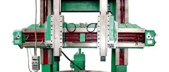
Rice. 1. This is what the first Soviet aggregate machines looked like
Since 1937, aggregate machines began to be widely used in the automotive and tractor industries (Fig. 1). In 1940, 25 modular machines were produced in the USSR. For this great service to the country, in March 1941, innovative engineer and scientist, one of the initiators of the introduction of modular machine tools, V. I. Dikushin was one of the first in the country to be awarded a high award - the Stalin Prize.
Design features
A design feature is the requirement to increase the reliability of the operation of standardized units and create conditions for quickly reconfiguring the machine to process another part. To ensure the above requirements, all-Union standards for the connecting dimensions of the main components were developed. Work is underway to create quickly reconfigurable aggregate machines using cyclic and numerical program control for rational use in mass production for group processing of parts [1].
Aggregate machines are most widespread in machining, when the part remains stationary and movement is imparted to the cutting tool. On an aggregate machine, machining can be carried out with tools from several sides, so a significant separation of operations is possible.
The principle of machine aggregation
The principle of aggregation is based on the fact that instead of developing all the units when designing a new machine, previously developed units are used, constructing a new machine from them. To do this, several similar units (units) of different sizes and power (called normalized or unified) are first developed, allowing the design of a machine quite well suited to the technological process of processing the part. In addition, they try to make these units self-acting, providing each with its own engine. Aggregate special machines have significant advantages over other machines:
- the ability to create equipment using the most advantageous technological process When it is planned to use modular machines, first they develop a process for processing the part, and then to carry out this process they assemble machines from ready-made components;
- multi-tool processing, which dramatically increases productivity;
- the ability to perform a variety of operations on one machine;
- allow you to constantly improve the equipment itself, since it is not the entire machine that needs to be modernized, but only the component that is outdated;
- favorable conditions are created for major repairs of machine tools;
- the reliability of equipment created from proven normalized components increases;
- special machines are assembled from serial components, which reduces their cost
Along with the advantages, modular machines also have disadvantages , which in recent years have greatly reduced the demand for these machines, even for mass production:
- for a new part, even slightly different from the previous one in the processed surfaces, it is necessary to make a new special machine;
- The machines are quite expensive and have a narrow scope of application - mass production.
To eliminate these contradictions, it is necessary that special machine equipment meet three main conditions:
- made it possible to make changeovers for processing different parts at a fairly high productivity (this is the most important thing, because the cost of fixed assets makes up a significant share of the cost of production);
- had a short design and manufacturing time;
- had a low cost and quick payback.
In general, modular machines meet these conditions under certain production conditions.
Unified units of aggregate machines
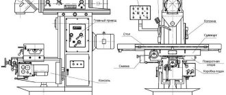
Unified or normalized units of aggregate machine tools are units whose designs are developed before a specific machine is designed. These units can be used in machines of different designs. These include (Fig. 2) a frame 7, a rotary dividing table 6, on which fixtures and workpieces are installed, and power headstocks 3. To install power heads on the machine, side frames 5, racks 4, and spacer plates are used. When multi-spindle machining of holes or when milling planes, drilling and milling attachments are attached to the power heads. The control of the machine is concentrated on the remote control, and all electrical equipment is located in the cabinet. Special units are constructed from normalized assembly units, arranging them as required by the design of the workpiece. The type of standardized units includes several hundred items of more than 2,500 designs and standard sizes and amounts to 75. .80% of machine components.
Rice. 2. Components of the aggregate machine : 1 - side frame; 2 - multi-spindle box; 3 — power headstock; 4 - stand; 5 — bed-stand; 6 — rotary dividing table; 7 — central bed; 8 - single-spindle boring head; 9 - power table
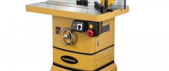
Modular special metal cutting machines
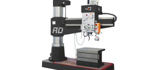
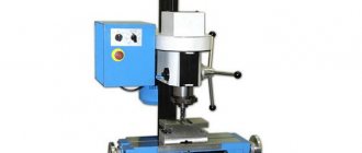
Special machines are designed to effectively perform individual technical tasks (Fig. 3). With minimal complexity they can be used as monofunctional (Table 1). The machines are also designed on the principle of a stationary workpiece processed by tools rotating around it.
Rice. 3. General view of Unitube machines
Table 1. Technical characteristics of MWZ machines
| Options | Machine models | ||
| MWZ 200 | MWZ 400 | MWZ 600 | |
| Workpiece diameter, mm: largest | 48,3…193,7 | 177,8…406,4 | 339,7…609,6 |
| least | 1,9…75/8 | 7…16 | 133/8…24 |
| Material yield strength, N/mm2 | 35…1000 | ||
| Cutting speed, m/min | 60…250 |
Note. At the request of the client, the equipment of modular metal-cutting machines MWZ can vary from the offered models MWZ 200-600.
Machine equipment: hydraulic system, lubrication system, CNC with electrical cabinet.
Peripherals: cooling device, chip conveyor, inter-machine transport and underwater means.
Automatic control technology:
- digital control systems - Siemens/Fanuc;
- modular, digital system of AC valve converters - Siemens/Fanuc;
- Rotating control panel with flat screen display.
Accessories: tools, test gauge, spare parts and wearing parts.
Assembly of aggregate machines
They are conventionally divided into four groups.
Rice. 3. Assembly of aggregate machines
1. The machines do not have a device for periodic transportation of processed parts, that is, the parts remain motionless throughout the entire processing cycle (Fig. 3, a). Having installed the workpiece, you can process surfaces on different sides of it that are precisely connected to each other, for example, holes in the gearbox housing or in the differential cup, the axle of the driveshaft crosspiece. Due to the fact that the device is stationary, fairly high processing accuracy can be achieved.
2. Aggregate machines have a rotary dividing table (Fig. 3, b). Typically a multi-position fixture is placed on it. Sequential processing of a part is carried out using several tools. A design with a table rotating around a central column is possible. Sometimes one large workpiece is installed in the center of the turntable.
3. The machines have a drum with a horizontal axis of rotation, on the edges of which there are devices for securing the workpieces (Fig. 3, c). On drum machines, parts are usually processed on two or three sides - these can be shafts, pipes, body parts. Small suspended heads allow processing to be extended to a larger number of sides.
4. The machines have a multi-position table with linear movement and are designed for processing parts with a large number of repeating elements or large ones (Fig. 3, d).
One or two positions (on opposite sides of the machine) are used for loading and removing workpieces.
In modular machines, the number of power units and tool spindles, the location of the spindle axes depend on the technological process implemented on the machine. There are single-unit and multi-unit machines, single-spindle and multi-spindle, horizontal, vertical, inclined and combined, single-sided and multi-sided.
On single-position machines, processing is completely completed with a constant position of the part. On multi-position machines with rotary index tables, parts are processed in parallel or sequentially at several positions in different positions relative to the tools.
Aggregate machines can be equipped with loading devices, and they will become automatic machines. The speakers operate both independently and as part of automatic lines.
The power heads of aggregate machines are the main normalized units that determine their technological capabilities. Power heads are designed to communicate to the tool the main movement, working feed and installation movements when drilling, countersinking, reaming and boring parts made of various materials. In most cases, cycles of movements are carried out, including a quick approach of the tool, a working feed (one or two depending on the technological process), holding on a hard stop (if necessary), a quick retraction and a stop at the end of the stroke. The movement program can be different and is carried out automatically from a cam installed inside the head body.
The main parameters of power heads, which characterize their technological capabilities and serve as the basis for choosing the design of power units, are the drive power of the main movement, the maximum feed force, the speed of the drive shaft of the head spindle, feed limits, the speed of rapid movements, the length of the working stroke, the accuracy of switching the mechanism feeds, overall dimensions.
Rice. 4. Small-sized power head
There are several main features of the classification of power heads:
- by type of feed drive - electromechanical (cam and screw), hydraulic and pneumohydraulic;
- according to the method of performing the feed movement - with a retractable quill and with a movable body;
- according to the developed feed power - self-acting (the feed drive is built into the housing) and non-self-acting (part of the mechanisms - the pump, the control panel - is located outside the head)
In Fig. Figure 4 shows a small-sized power head with a flat-cam feed drive and a retractable quill. The head housing 2 is mounted on a slide 3 fixed to the frame. During operation, the head body is motionless; When setting up the machine, the body can be moved manually (using a screw) along the slide. If it is necessary to move the head while the machine is operating, self-propelled slides are used. Spindle 1 is rotated by an electric motor 5 using a belt or gear drive 4.
Rice. 5. Kinematic diagram of a self-acting power head
The principle of operation of the head is as follows (Fig. 5). From the electric motor 1, through replaceable pulleys 11, the rotational motion is transmitted to a hollow shaft 4, which has internal splines for connection to the spindle 8. The hollow shaft has a worm 10, from which, through a worm gear 3, replaceable wheels 2 and 4 and wheel 5, rotation is transmitted to the gear 7 , which has a cam 6 at its end. A stop, rigidly connected to the spindle quill, is pressed against the cam using a spring. The cam, pressing the stop, extends the spindle to the right, providing rapid and working feeds, and then the spring returns the spindle to its original position. The head mechanisms are protected from overload by a ball clutch Mf1, mounted in the sleeve of the worm gear 3. The main movement is adjusted by replaceable pulleys 11, and the feed amount is adjusted by replaceable gears 2 and 4
Drum-cam power heads with a movable quill or movable body are used for drilling, milling and threading operations. Their power is 0.1. . . 6 kW. The basic kinematic diagram of such a head does not differ from the diagram of a flat-cam head.
A power head with a hydraulic feed drive is shown in Fig. 6. Rotation from the motor 11 through a pair of gears 1-10 is transmitted through a connection 9 to the spindle 6 of the head. The spindle is installed inside the quill 4, the feed of which is communicated by the hydraulic cylinder 7. When the piston 8 moves to the right, the spindle slides inside the sleeve 5, with which it has a movable connection, carrying out the feed movement. On the side surfaces of the power head, stops 2 for electrical and hydraulic control equipment 3 are installed.
Rice. 6. Hydraulic power head
\
Hydraulic power heads are used to perform both light and heavy work when machining medium and large parts. These heads are suitable for performing power work: main motion drive 0.27. . .30 kW, feed force 0.4... .100 kN.
The hydraulic drive provides stepless feed control within 0.12. . .14 mm/s and fast movement speed 50. . .125 mm/s. Thanks to the precise switching from fast strokes to working feeds and vice versa (0.18 ... 0.47 mm), short idle times are ensured. The tool rotation speed is up to 9000 min-1, and when drilling holes with a diameter of less than 1 mm, the spindle makes up to 24,000 min-1. Great rigidity, reliable overload protection and self-lubrication of drive parts ensure high performance of the power head. The disadvantage is that it is difficult to operate and repair hydraulic panels, the feed is unstable with sharply changing cutting forces and it is impossible to cut threads.
Rapid movements in hydraulically driven aggregate machines take up to 50% of the operating time. Increasing the speed of rapid strokes to values of more than 5 m/s causes an increase in inertia and travel time. The introduction of a two-speed approach with switching to a speed of 2 m/s increases the stability of the switching point and reduces switching time by 27-50%
Electromechanical screw heads are used for drilling, boring, and especially often thread-cutting operations. Self-acting power heads provide basic movements and rapid approach and retraction of the cutting tool. The longest tool stroke, depending on the design of the slide, is 500. .800 mm, feed limits 16.4. . .349 mm/min, electric motor power up to 14 kW.
Pneumohydraulic power heads operate using compressed air in combination with hydraulic control of the flow rate. They are produced in two types: with direct action of air on the oil (PGSG models) or quill type with separation of air and oil by an elastic diaphragm (GS-2M models). The main movement in the pneumohydraulic power head - the rotation of the spindles with tools - is carried out from the electric motor through a gear drive, and the forward movement with working feed and the reverse movement are from the piston of the power cylinder using compressed air.
In pneumatic power heads, rotation of the spindle is transmitted from a turbine installed in the head body, and the feed pneumatic cylinder is also located there. Before the tool comes into contact with the product, the spindle moves quickly, and then the working feed follows, which in such a head is not adjustable, but depends on the hardness of the material being processed.
Pneumatic and pneumohydraulic power heads are simple in design, easy to reconfigure, with a self-lubricating system of rubbing surfaces, and stepless feed control. But they have low feed forces and are energy-intensive due to the cost of obtaining compressed air.
General classification
Metal processing equipment is divided into 11 groups:
- Metal lathes. External and internal surfaces of rotation are processed. They have one thing in common: rotation of the part around its axis.
- Drilling machines. This group also includes boring machines. Used for passing through and blind holes. They are united by the rotation of the working tool and its simultaneous feeding. In horizontal boring mechanisms, feeding occurs due to the movement of the work table with the fixed part.
- Grinding machines. All such machines use an abrasive grinding wheel as a working tool.
- Polishing and finishing machines. A common feature is the use of abrasive wheels and polishing pastes.
- Gear processing machines. Designed for cutting gear and wheel teeth. This also includes grinding machines.
- Milling machines. In this group, the working tool is a multi-edge milling cutter.
- Planing machines. For these machines, the working stroke is a reciprocating movement of the cutter or workpiece.
- Slitting machines. They are used for dividing into parts by cutting a metal profile (angle, channel, rod, etc.).
- Broaching machines. The working tools are special multi-blade broaches.
- Thread processing machines. This includes equipment specifically designed for thread cutting. This group does not include lathes.
- Auxiliary and miscellaneous machines. They belong to a separate group and perform various auxiliary operations.
Classification by type
Equipment of the same type may have different layouts. A milling machine can be called horizontal or vertical - based on the location of the spindle axis. Kinematic schemes for transmitting movements, control systems, and cutting accuracy parameters differ.
Machines of the same type with a similar layout and kinematics, but having different sizes, will be combined into a size range. For example, gear hobbing machines are divided into 12 standard sizes depending on the parts being manufactured (from 80 mm to 12,000 mm). Each standard size of a machine designed for a specific processing of parts is called a model. Each model has its own designations: a combination of numbers and letters indicating the machine group, the maximum dimensions of the workpiece, the difference from the base model.
Classification by versatility
Processing mechanisms of the same group can perform different tasks:
- Universal ones process a wide range of products. The dimensions of the blanks may vary. Capable of performing any technological operations provided for this group.
- Specialized ones produce parts of the same type (body parts, shafts, similar in shape, but different in size).
- Special ones perform operations on one part of various sizes.
Classification by degree of accuracy
The degree of processing accuracy on a given machine is indicated by the letter included in its designation:
- N - normal accuracy;
- P - increased accuracy;
- B - high accuracy;
- A - particularly high accuracy;
- C - especially precise master machines.
Example: 16K20P - a lathe with increased accuracy.
Classification by degree of automation
Processing equipment is divided into automatic and semi-automatic. The working cycle of the machines is completely autonomous. In semi-automatic machines, loading of workpieces and removal of processed products is carried out by the operator. It also launches the next processing cycle.
Integrated automation of large-scale production of metal products involves the installation of automatic production lines from separate automatic machines. Products are produced in small batches using flexible production modules.
Machines that produce products under CNC control are designated by the letter C (cycle) or F. The numbers indicate a feature of the control system:
- F1 - digital display and preliminary selection of coordinates;
- F2 - positional control system;
- F3 - loop control system;
- F4 is a universal control system.
For example, the range of CNC metal lathes from the StankoMashKompleks company can be viewed at the link provided.
Classification by weight
Depending on the mass of manufactured parts, machines are divided into:
- lightweight, weighing up to 1000 kg;
- medium, weighing up to 10,000 kg;
- heavy, weighing from 10,000 kg, which, in turn, are divided into large (16,000-30,000 kg) and actually heavy (up to 100,000 kg);
- especially heavy - over 100,000 kg.
Machine numbering
Identification of any metalworking machine is based on assigning an alphanumeric code to it.
The numbers indicate which group the machine belongs to (lathe, milling, etc.), indicate the type and nominal size of the equipment. By deciphering the numbering, you can find out the height of the centers, the maximum dimensions of the workpieces or the drilling diameters of the workpieces.
Power tables and headstocks
To perform operations that require large amounts of power: milling, boring, trimming large ends, power heads require increased rigidity. The previously described power heads do not meet this requirement. To increase rigidity, the design had to be changed: the main movement mechanism was separated from the feed mechanism, and two units were obtained - a power table and a power headstock. In Fig. 7 shows such a unit.
Rice. 7. Power table with a power head mounted on it
The basic one is the power table 4, installed in the guide slide 5. The table is driven using two electric motors, a gearbox 1 and a screw-nut pair. Depending on the purpose of the machine, drilling, milling, turning, scoring, diamond boring and other power headstocks 2 are installed on the power table. You can install a clamping device with the workpiece being processed. The headstock has a separate main movement drive, ending with a drive shaft 3, which rotates the spindle of the spindle box. The box is installed on plane A of the power table and secured to plane B of the power headstock. The operating cycle of the unit is ensured by stops 6 and limit switches.
The resulting unit provides a reliable and stable supply within 0.2. . . 2.2 mm/s, fast strokes at a speed of 0.07. . . 0.11 m/s, feed force 3. . .100 kN and threading capability. The installed power of the main movement drive is from 0.8 to 30 kW. At the same time, this unit has a complex electrical circuit, step change in feed, it is difficult to obtain very small feeds. The large mass of the equipment reduces the accuracy of command execution during fast movements. The cycle of table movements is controlled by adjustable stops and contactless track switches of the BVK type.
In power tables, along with sliding screw pairs, rolling screw pairs are used, which are characterized by high durability and ensure high durability of the cutting tool due to the smooth movement of the table. Power tables can operate in horizontal, vertical and inclined positions. When installing the table vertically or inclined, its moving part is balanced by a counterweight, which is placed inside the stand and suspended on bushing roller chains or steel ropes.
Power tables are used as feed mechanisms for aggregate machines when processing medium and large parts. The main working cycle of power tables, as well as power heads: accelerated approach - working feed (one or two) - holding on a hard stop - quick withdrawal Depending on the standard size, the maximum stroke length of the table is 250. . .1250 mm, and the maximum feed force is 6.3…100 kN.
When using a table with a hydraulic cylinder, stepless feed control and sufficient accuracy of switching from high speed to working feed are provided (runout up to 0.5 mm).
A power table with a screw feed drive (Fig. consists of the table itself (moving plate) 17, a slide 18 and a gearbox. A device with a workpiece or components that impart the main rotational movement to the tools (drilling, boring, milling, etc.) are installed on the table. The table provides the workpiece or headstock with fast approach, working feed and fast withdrawal.It receives working feed from electric motor 1 with the electromagnetic clutch 13 turned on through gears 2-4, 3-6, replaceable 5 and 7 and gears 15-16, 9-12 , 10-11 wheels.The maximum feed force is regulated by friction clutch 14
Rice. 8. Kinematic diagram of the force table
When it is necessary to ensure the perpendicularity of the axis of the hole and its end, the latter is processed on a rigid stop. In this case, the table rests against the adjusted screw, and the safety clutch 14 slips. Fast supply and retraction of the table is provided by the electric motor 8 through gears 10-11 when the electromagnetic clutch 13 is turned off.
In addition to the electromechanical feed drive, modular machines are equipped with power tables with a hydraulic drive. Such a table moves along a guide plate using a hydraulic cylinder and can be used as a feed mechanism when processing medium and large parts. A power table with a hydraulic drive is otherwise called a rolling table.
Milling headstocks of modular machines are designed for roughing and finishing milling with one spindle. They are installed on cross and power tables, which impart feed movement to them. Headstocks can be pinless, when the position of the cutter relative to the headstock does not change and adjusting the cutter to size is possible only when the headstock is installed on a cross table. With quill stocks, the movement of the quill can be either manual or automatic, with a rebound of the quill. On power tables, the headstocks are mounted on a slide. The power of milling headstocks of the first type is from 1.5 to 30 kW with a spindle speed range of 41. .2500 min-1 for low-power ones up to 16. . .698 min-1 for heavy milling heads. Quill heads are less powerful (from 4 to 18.5 kW) at the same spindle speeds.
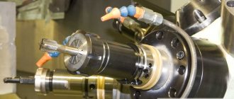
Boring heads (Fig. 9) have modifications designed to perform roughing and semi-finishing operations: boring, trimming ends, countersinking, and for finishing operations, which perform boring and trimming ends and ensure the production of holes of the 7th quality. Boring heads can have a mechanism for automatic adjustment of the cutting tool. They are installed on power tables, which communicate the feed movement to them, or stationary, when the feed movement is communicated to the workpiece.
Rice. 9. Boring head : 1 - spindle; 2 - body; 3 - drive pulley or gear.
Scoring and boring headstocks simultaneously carry out boring of the hole and trimming of the ends (grooving). These headstocks are installed on power or rolling tables.
The rotation speeds of headstock spindles used on aggregate machines are within 16. . .5000 min-1. They can bore holes with a diameter of up to 200 mm, and the torque and axial force can reach 6300 N • m and 25000 N, respectively.
Group Description
Machines for processing deep holes produced by the Ryazan Machine Tool Plant meet these requirements.
Based on a variety of practical problems, special machines of various sizes and designs have been developed.
The following forms may be used:
Structural form No. 1 (lathe): Based on a rotating product in the workpiece headstock chuck and roller rests. The stem with the installed tool is attached to the stem headstock. Holes are machined using a non-rotating tool.
Structural form No. 2 (Turning machine): Basing a rotating product in the workpiece headstock chuck and roller rests. Depending on technological needs, processing can be carried out with a rotating product using either a non-rotating or a rotating tool.
Structural form No. 3 (Swivel-type machine): Basing a rotating product in the workpiece headstock chucks and roller rests. The ends of hollow workpieces are easily accessible for measurements and tool changes; work using the “pull boring” method. Processing occurs with a non-rotating tool.
Structural form No. 4 (Swivel-type machine): Basing a rotating product in the workpiece headstock chucks and roller rests. Processing can be carried out with a rotating product, either with a non-rotating or a rotating tool.
Structural form No. 5 (cased machine): Basement of a non-rotating product in fixtures. Holes are machined using a rotating tool.
Rotary index tables
In addition to devices for linear movement, aggregate machines often use rotary dividing tables designed for attaching devices with workpieces to them and periodically rotating them at a certain angle. These tables move workpieces from one working position to another and, very importantly, accurately fix the workpiece relative to the cutting tools. The tables rotate in horizontal and vertical planes. Dividing tables are most often made disk-shaped or ring-shaped with rotation in the horizontal plane, and also called “drum” - for rotation in the vertical plane. In the latter case, fixtures with parts are located on the periphery of the drum and the part can be simultaneously processed from both sides.
The electromechanical rotary dividing table consists of the table itself (faceplate), base and gearbox. The lower plane of the table is installed on the mating plane of the frame. Various devices are used as the turning mechanism. This could be a Maltese mechanism or some other drive. But a prerequisite is the presence of rotation units, orientation in the desired position and a fixation device.
Deep drilling and boring machines
- About the company About us
- Trademarks
- Product quality
- Patent work
- Security service warns!
- Machines produced by RSZ
- Spare parts
- Lathe chucks
- Find a workshop for rent
- News
Basic parts of modular machines
The beds and racks of modular machines belong to the basic units (Fig. 10). A rotary dividing table is installed on the frame 2. Side frames 5 are attached to its side edges. A loading position is organized at the front edge, and one of the side edges (for example, cut as a chamfer) is used for removing chips. A power table is placed on a rack 4 mounted on a stand 3 in a vertical position. The rack has a counterweight that serves to balance the moving units: table, spindle box with thrust square 1 and tool adjustment, as well as the jig plate. On the side frames 5, power tables, power heads or vertical racks are installed. On top of the side frame there are two plates for basing these units. The side frame is attached to the middle frame using a flange. The frame and rack are made of cast iron or welded from rolled steel sheets.
Rice. 10. Basic parts of a modular machine
Special units of aggregate machines are:
- instrumental adjustments;
- spindle boxes;
- devices for fastening parts.
The design of these units is determined by the design of the workpiece and the technological process being carried out.
Instrumental setup of a specific aggregate machine includes a set of extensions in which the cutting tool is installed, copiers with which threads are cut, the cutting tool itself (both universal and special) and other equipment and determines the type, quantity and location of their installation in the working positions. Tool setup allows you to configure the machine to perform a specific job.
Spindle boxes and attachments are designed to accommodate working spindles and gears that transmit rotation to the spindles from the power head drive shaft. Small spindle boxes (nozzles) are mounted on the power head housing, and large ones are mounted on the power table and attached to plane A of the thrust square (see Fig. 10), which is fixed to the table by plane B. Multi-spindle boxes allow you to process a large number of holes with parallel axes. In most cases they are intended.
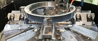
for processing parts along guide bushings (jigs), they perform all kinds of hole processing (box modifications are available for threading) and can have up to 80 spindles 1 (Fig. 11).
Rice. 11. General view of the spindle box attached to the square
Rice. 12. Section of the spindle box with a square : 1 - intermediate shaft; 2 — reinforced spindle; 3 — drilling spindle; 4 — front plate; 5 — shaft for manual rotation of spindles; 6 — rear plate; 7 - drive gear; 8 - coupling; 9 - square; 10 - electric motor.
In the box, rotation is transmitted from the input shaft with drive gear 7 (Fig. 12) to all spindles located at the required distance from each other. The spindles contain tools that are identical or different in both name and size. Each spindle rotates in the desired direction at a given speed and transmits the required torque to the tool. Kinematics, the location of the spindles and the dimensions of the spindle box are determined by the transitions performed on the machine, the shape, dimensions and material of the workpiece, and the layout of the machine.
The design of the spindle box makes it possible to obtain a wide range of speeds on the spindles, and the range of unified spindles allows for mounting adapter tool holders with a diameter of 19, 26, 36, 44, 60, 80 mm. Thus, the spindle box allows for different combinations of tool types, processing diameters and cutting conditions.
When processing a part, it is not always possible to provide the tool with additional direction in the drill bushings. In such cases, a more rigid design of the spindle group in terms of precision characteristics is required. Increased rigidity is achieved by increasing the distance between the spindle supports and installing a double-row roller bearing with an internal tapered hole in the front spindle support. In addition, the design of the tool holder mounting in the spindle is changed. Typically, the tool holder is secured by two screws that press the tool holder to one side of the mounting hole in the spindle. The eccentricity of the toolholder is extremely undesirable, especially when machining a part without a jig, so a self-centering collet is used to fix the toolholder in a reinforced spindle. A spindle made with the listed changes is called a rigid spindle (Fig. 13).
Rice. 13. Design of a rigid spindle of a modular machine : 1, 9 - nut; 2 - collet; 3, 5, 12 - flange; 4 - cuff; 6 — bushing; 7 — thrust bearing; 8 - locking screw; 10 - threaded key; 11 - glass; 13 - radial double-row roller bearing.
Rice. 14. Multi-spindle attachment : 1 - spindle; 2 - rolling pin; 3 - holder; 4 — thrust ball bearing; 5 — gears; 6 — intermediate shaft; 7 - bottom cover; 8 — head body; 9 - top cover.
A small-sized spindle box (attachment) for a power head with a retractable quill (see Fig. 4) is shown in Fig. 14. The nozzle body consists of three parts: holder 3, body 8 and cover 7. The nozzle flange is installed on the power head quill, and the nozzle holder 3 with two guide pins 2 is attached to its body. The drive gear 5 (Fig. 14), which rotates all the spindles of the nozzle, is rigidly connected to the spindle 1 of the head (see Fig. 4).
Multi-spindle attachments are a simplified version of multi-spindle boxes and are used for simultaneous processing (drilling, reaming, threading) of several (from 2 to 10) holes with parallel axes.
In modular machines, despite their great similarity, it is impossible to completely unify the design of spindle boxes, since there are countless options for the number of spindles, their types and locations, and the center-to-center distances between them. Therefore, it is not the design that is unified, but the casting kits, spindles with supports, intermediate shafts with supports, gears, rolling bearings, spacers, lubrication units and all other parts, including housings prepared for boring. The original drawings are the location of the holes on the box body and the assembly drawing.
Devices for fastening parts on aggregate machines must ensure precise positioning, reliable fastening, and a compact design built into the limited space of the rotary table. At the same time, it is necessary to ensure reliable removal of chips, convenience and maximum automation of loading and unloading and fastening and unfastening of the workpiece, automation of auxiliary operations, fixing and unfastening, and checking the accuracy of installation. By design, clamping devices can be single or multi-place. Drives are manual, mechanized and automated. Manual drives are used mainly in auxiliary, fixing and less often clamping mechanisms. Mechanized and automated clamping drives use pneumatic and hydraulic cylinders, electromechanical and hydromechanical keys.
Deep Drilling Process and Methods
Deep drilling is used only when it is necessary to obtain a hole of a certain accuracy and quality and this method will be the best in terms of performance. When drilling deep holes, the main problem arises - removal of chips and cutting fluid, therefore constant chip removal is forced by feeding under coolant or compressed air pressure.
Deep drilling can be carried out using two methods:
- solid – a hollow hole is drilled into the part (traditional drilling);
- ring - a part of the material in the form of a ring is drilled into the part so that a rod remains inside. If the hole is through, then the rod is separated from the part; if it is blind, the rod is removed using special methods.
This method is used when it is necessary to process holes longer than 80 drill diameters.