When replacing plastic pipelines, the need arises for reliable connection of individual elements; such installation can be carried out in several ways. For polyethylene pipes, this is the use of welding, which can be done end-to-end or using an element such as an electric coupling. There is also a mechanical connection method, but it does not always provide high reliability and tightness.
Electrofusion welding for polyethylene pipes is one of the most reliable and durable welding methods available today.
There are three methods in total today:
- mechanical connection using fittings;
- butt welding, but it is applicable only under certain conditions, when the ends of the pipe can be rigidly fixed;
- electrofusion welding, which is used in hard-to-reach conditions, for example, in wells, technical holes, narrow ditches, and during urgent repairs.
Butt welding: connection principle
Methods for connecting PE pipes.
The use of butt welding is a simple heating of the ends of a plastic pipeline, in which all welded elements are heated to a viscous-fluid state, after which the ends of the polyethylene pipes are connected under pressure. When performing such work, the product must be firmly fixed; shifts and other movements during welding and cooling are not allowed.
This technology is very simple, but it is not possible in all situations, only for connecting pipelines with the same diameter and the same grade of polyethylene. It is impossible to cook plastics with different characteristics using this method. The working conditions here are as follows:
- the thickness of the pipe walls should not be less than 4.5 mm;
- Welding can only be done in the temperature range from -15 to +45 degrees;
- Electricity consumption with this method is insignificant;
- when welding there is no need to use complex equipment;
- This method is used only when it is possible to reliably fix the ends of plastic pipes; butt welding is not suitable for working in complex, hard-to-reach places - only an electric coupling is suitable.
Advantages of connections using electrofusion couplings
Welding of polyethylene pipes is ideal when there is a need to repair pipes in the shortest possible time.
The use of electric couplings for connecting polyethylene pipes of any diameter is preferable when the butt welding method is not so convenient and practical. As a rule, these are sewer wells, very narrow and inconvenient channels, installation holes in the foundations and walls of buildings. That is, the method of welding using a coupling is excellent in cases where it is simply impossible to install a joining machine.
Another advantage of using this connection method is that it is appropriate in case of various accidents, in case of damage to polyethylene pipes, when problems need to be fixed in the shortest possible time.
In addition, electric welding is very simple, does not require special knowledge, the readiness of the connection is easy to establish using special holes on the coupling.
The correct temperature required by the welding method is easy to determine if you use a modern machine - it has the ability to read the required information directly from the electrofusion barcode.
For the work, the simplest tools are used, including only a device for stripping the ends of the pipeline, the electric couplings themselves and a welding machine intended for connection.
Applications
In the late 1970s and early 80s they were used in high-speed line printers to stop a rotating drum with 96 or more columns and 40 or more rows containing the alphabet. The drum was stopped momentarily by the clutch while the hammers struck the ink and paper in the corresponding column. Each rotation of the reel produced a full line of text and symbols. These drums spun at speeds ranging from 300 to 1200 rpm.
Factories also used them to regulate the speed of unwinding a spool of material. A real-life example of this can be found in paper mills. Paper mills require material to be fed to their rolls at a constant rate. These clutches allow material to be fed to the rollers at the desired speed while maintaining tension on the material. Magnetic particle couplings are also used in cycle control. They allow cycles to have constant torque while completing the cycle. A great example of this is a machine that caps bottles.
Magnetic particle clutches can also be found in the gym. They are used in treadmills to smoothly control the speed of the belt. It is also used to protect the machine's motor from overload when used by people of different weights.
Stages of welding polyethylene pipes using an electric coupling
Sequence of work when connecting pipes with a coupling to the Z.N.: a - preparation of the connection; b, c, d - stages of joint installation; d - joint mounted for welding; 1 - pipe; 2 — mark for the depth of fitting the coupling and removing the oxide layer from the pipe; 3 - coupling; 4 - Z.N.; 5 - terminals; 6 — positioner; 7 - cables with welding machine terminals
Welding plastic pipes using an electric coupling is carried out as follows:
- First, it is necessary to carry out a set of preparatory work, which includes cleaning the surface of the two pipes being connected, removing the oxide layer and dirt. This can be done using a knife, scraper or a special mechanized device. It is quite expensive, but when installing large-diameter pipes, using a conventional knife is extremely difficult.
- To put on the coupling, it is recommended to use a special positioner, which will allow all connected parts to take the correct position. A special rounding overlay helps to remove some of the ovality of the product.
- All surfaces to be welded will have to be degreased. This procedure must be carried out both inside and outside;
- If it is raining or snowing outside, then all elements, pipes, couplings, etc. should be removed under a canopy and welding should continue there. The pipe should be connected only taking into account this rule, otherwise you can’t even dream of a reliable fastening.
- After completing the preparation of polyethylene pipes, you can proceed directly to the welding itself. The electric coupling is placed on the end of one pipe, using a regular hammer, the ends of the pipe and the coupling are aligned, after which a mark should be made at the end of the second pipe exactly halfway. Next, the ends of the polyethylene pipes are aligned coaxially, and the coupling is pushed up to the mark made.
- Wires coming from the welding machine are inserted into special terminals of the electrofusion; the welding process itself is carried out automatically. Modern welding devices for plastic pipes allow you to set the temperature of the connection by reading the barcode that is printed on the label of the coupling being sold.
- after this, the welding is considered complete, which is noticeable by the special holes that the electric coupling has. Drops of molten polyethylene begin to protrude from these holes, after which the wires can be removed from the coupling terminals.
- the last stage is the complete cooling of all welded sections of plastic pipes, which must not be touched or moved.
What is an electric coupling?
An electromagnetic clutch is a special device for solving a wide variety of problems, most of which involve connecting and disconnecting a pair in mesh. Electromagnetic couplings are produced for machine tools and other components of vehicles or diesel locomotives. There are several main types of such structures:
- Friction type mechanisms are cone and disk.
- A gear-type electromagnetic clutch is considered a specific design option, since the working part is represented by a combination of various teeth.
- Powder electromagnetic coupling is a modern option as it provides axial displacement when required.
The electric coupling is an intermediate connecting element. The principle of operation is to use the basic properties of electric current to generate electromotive force.
At the same time, it can perform a variety of functions, for example, protecting the main device from overheating or control.
The main functions of couplings or why they are so often used in repair and restoration work
Such a small part as a coupling has not only a specific purpose, but also a wide range of functionality. Let us outline the most basic tasks of the coupling. First, the ETM coupling is designed to provide strong connections when two typical parts are assembled into a system and continue to operate. Secondly, a small device with a connecting function is responsible for the tightness of the line without leaks and unwanted deformation. Thirdly, certain types of couplings can also protect against corrosion.
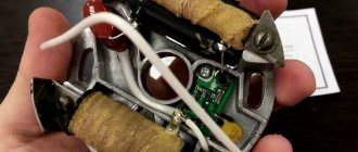
The operating principle of the electromagnetic clutch
An electromagnetic clutch can have a very different design, but there is also a classic version. Its features are as follows:
- The main elements can be called two rotors, one of which is represented by an iron disk with a thin end protrusion.
- The internal part is equipped with pole pieces that provide radial displacement. To transmit current, a winding is created and connected to the power source through slip rings. Part of this element is located on the shaft.
- The magnetic coupling under consideration has a second rotor, which is represented by a cylindrical shaft with special grooves located parallel to the main axis. They are created so that special bars with pole pieces can be inserted.
The permanent magnet coupling in question has a rather complex design, which ensures accurate and reliable operation. The operating principle of the device is as follows:
- When current appears, an electromagnetic field arises, which intersects with the conductor and begins to interact.
- Such a combination causes the emergence of electromotive force. It may be quite sufficient to move the moving element, taking into account overcoming a certain force.
- In the manufacture of this part, a copper bar is used, which ensures the closure of the circuit. A current passes through them, due to which an electromagnetic force appears.
- The resulting fields provide a driven rotor behind the leading one, while the delay is insignificant.
A similar operating principle is used to create a wide variety of mechanisms. In this case, the device of the machine makes it possible to stop the transmission of torque within a few fractions of a second, which determines its distribution.
Demagnetization of the electromagnetic clutch occurs by disconnecting the power source. In this case, the special properties of the material determine that the magnetic field disappears almost immediately, due to which the reverse movement of the moving element occurs. The used electromagnet windings are designed for a sufficiently large number of coupling and disengagement of the driving element with the driven one.
When considering what an electromagnetic clutch is, you also need to pay attention to the properties of the materials used in its manufacture.
Only special alloys have magnetic properties that provide the required operating conditions.
The transmission of torque to the clutch can be carried out from an electric motor and other similar elements. The dimensions of all dimensions are in most cases standardized, but it is possible to order the production of the mechanism to order. Classification is usually carried out according to the area of application and many other characteristics.
Electromagnetic couplingsHome » Technologies » Industrial equipment and spare parts
Electromagnetic clutches operate under the influence of a magnetic field created by a built-in coil, the energy of which comes from a DC motor.
According to their mode of action and purpose, electromagnetic couplings can be divided into two groups:
- slip clutches:
- clutches.
Electromagnetic slip clutches, in addition to starting and stopping, allow you to smoothly change the rotation speed of the drive mechanism. Clutches are designed only to turn the driven mechanism on and off and do not allow smooth adjustment of the rotation speed. Electromagnetic slip clutches, in turn, can be divided into three main categories:
- with a massive anchor,
- high-speed - with a thin-walled rotor,
- with ferromagnetic powder.
The operating principle of electromagnetic sliding clutches with a massive armature is based on the same physical laws and properties as the operation of an asynchronous electric motor. The rotating magnetic field of the slip clutch is created by an inductor having an excitation winding. The field rotation is carried out due to the rotation of the inductor from an external source of mechanical energy, for example an asynchronous electric motor (in our case it is a DC motor). The currents induced in the clutch armature by the rotating magnetic field interact with it, and the clutch armature rotates in the same way as the rotor of an asynchronous motor. Unlike electromagnetic clutches with a massive armature, the driven part of high-speed sliding clutches is a low-inertia thin-walled aluminum rotor located in the working air gap of the clutch between the armature and the inductor. In this case, both of them are installed on a common drive shaft of the coupling, and the force interaction that ensures the rotation of the rotor is carried out between the currents induced in the thin-walled rotor and the magnetic field created by the inductor. Ferropowder electromagnetic clutches are similar in principle to electromagnetic sliding clutches with a massive armature, but the working gap in them is filled with a suspension of ferromagnetic powder and liquid mineral oil. This measure makes it possible, with the same dimensions, to increase the torque transmitted by the clutch by an order of magnitude due to an increase in the magnetic flux in the working gap, as well as due to friction between the particles of ferromagnetic powder. The operating principle of electromagnetic clutches is based on the frictional interaction of the driving and driven discs. The interaction of the disks occurs when the movable armature is pressed on them due to its attraction to the coupling body by the magnetic field created by the DC excitation winding.
Gear couplings are especially popular; they combine the advantages of mechanical gearing and the accuracy and stability of electrical actuation and can transmit very large torques. Each of these types has its own advantages and disadvantages.
Electromagnetic sliding clutches with a massive armature are relatively simple in design and operation, they allow you to smoothly regulate the speed of rotation of the driven mechanism, but they have a significant moment of inertia of the driven part and do not provide the desired interaction when the speed increases. High-speed electromagnetic sliding clutches also allow smooth adjustment of the rotation speed of the driven mechanism, provide high performance during acceleration and braking, but are complex in design and operation and require forced air cooling. Ferropowder electromagnetic couplings provide broad performance with small dimensions, ensure the transmission of large torques, smoothly regulate the speed of rotation of the driven mechanism, but their use and design are complex, they require regular change of ferropowder, combating its leakage through gaps and also require a forced cooling system, usually watery. Electromagnetic clutches (friction) are simple in design, provide high performance during acceleration and braking, with small dimensions they provide the transmission of large torques, but practically do not allow smooth adjustment of the rotation speed of the driven mechanism and in some cases require an oil bath for lubrication and cooling.
www.servomh.ru offers the widest range of these products.
Electromagnetic couplings with a moving and rotating coil, with bearings, slip rings, non-magnetic ring gear, non-magnetic core, electromagnetic brakes, etc.
We work to order throughout Russia.
Classification of electric couplings
In most cases, electrofusion couplings are classified according to the area in which they are used. The most commonly used is an electromagnetic friction clutch. It has the following properties:
- The device can be used to reduce the likelihood of exposure to impulse loads.
- At idle, design features determine minor losses. This point determines that the main elements do not heat up during operation.
- It is possible to quickly start the mechanism even if it is under heavy load.
The type of mechanism under consideration is divided into several main types:
Quite often there is an electromagnetic brake clutch, which can reduce the number of revolutions during operation.
The air conditioning compressor version is presented in the form of a unit, which consists of the following elements:
- Electromagnetic type coils. It is made using special alloys that are characterized by certain properties. The coil is required to directly generate the electromagnetic field.
- Pressure type plates. This structural element must be characterized by high strength.
- A pulley that transmits force from an electric motor. A drive of this type has become quite widespread, as it protects the device from overheating under heavy load. By changing the pulleys, it is possible to regulate the number of revolutions at the output.
In this case, electricity is supplied to the coil, which forms an electromagnetic field. Due to this, the pressure plate is attracted to the pulley. Such a movement gives freedom to the shaft, and the mechanism begins to work.
Compressor units have become very widespread. That is why you need to pay attention to the following defects:
- Quite often there is a situation when the pulley bearing is deformed. In this case, it is enough to replace the element.
- The pressure plate is made of thin metal, so it may become deformed during use. In addition, the problem arises if the gap is set incorrectly.
- There is a situation where the clutch itself burns out. It is most often associated with the high voltage that is applied to the coil.
Electric coupling - how does it work?
An important element of the internal structure of a car is the clutch. Technology today does not stand still, so different car models can have different elements installed. It is necessary to clearly understand the issue of electric couplings - something little known.
What is an electric coupling?
An electromagnetic coupling is a device designed to connect and disconnect a pair of main shafts or a shaft and a part that sits loosely on it. There are many areas of application for electromagnetic couplings. In addition to being used in the design of vehicles, such devices are widely used in diesel locomotives, installed in metal cutting machines and similar devices. But different types of couplings are used in different mechanisms. Even Kamaz and Gazelle vehicles have different types of couplings.
The following types of electromagnetic couplings have been identified:
— cone and disk friction electric couplings;
— gear electric coupling (the teeth are located on the end surface of the coupling);
— powder or liquid electric coupling (the magnetically conductive gap between the parts of the coupling is filled with a powdery mixture with a liquid consistency containing ferrimagnetic powder).
Classification of electric couplings
We will consider the classification based on the area where this or that device is used.
Electromagnetic couplings ETM
This device is designed to protect mechanisms and devices from impulse overloads. Such a clutch provides small losses at idle. This has an extremely beneficial effect on the thermal balance of the system, and also allows the device to quickly start up, even if it is under load. Such couplings, in turn, are divided into:
— contact electric couplings;
- electric brake couplings;
— contactless electric couplings.
Electric couplings for air conditioning compressor
This electric coupling is presented in the form of a unit that must be installed in front of the compressor, consisting of:
— electromagnetic coil;
- pressure plate;
- a pulley that is driven by a belt.
The connection between the pressure plate and the main shaft is very direct, but the coil and pulley must be installed on the front wall of the compressor. When power is applied to the coil, a magnetic field is generated that attracts the pressure plate to the pulley. Due to this, the compressor shaft begins to move, the pulley and plate also begin to rotate, and together.
The electric coupling of the air conditioning compressor can produce different results during diagnostics, so you will probably think about the results obtained. In reality, malfunctions can occur due to:
— defects in the pulley bearings (in this case, the bearings need to be replaced);
— the pressure plate is broken (this happens because the gap was initially set incorrectly);
- the clutch itself has “burned out” (a sign that there are serious compressor problems inside the car, so a thorough diagnosis needs to be carried out).
Fan drive electric coupling
This device is widely used in engine cooling systems. the function of such a coupling is to maintain a given temperature regime (in the range from 85 to 90 degrees). If such a clutch is installed in your car, then:
— in winter, the temperature of the engine will be better maintained when the engine is running;
— power losses on the fan drive will be significantly reduced, and this will significantly reduce fuel consumption.
Electric clutch
They are divided into:
— mechanical electric couplings;
— hydraulic electric couplings;
— clutches.
The most common is the latter type of electric coupling, and they are also divided into the following categories:
1) By type of friction: dry and wet (working in oil);
2) By switching mode: permanently and non-permanently closed;
3) By the number of slave disks: single-, double- and multi-disk;
4) By type of pressure springs and position: with a spring located on the periphery of the pressure disk and with a central diaphragm spring;
5) By type of control: with hydraulic, mechanical and combined drive.
Safety elements, electromagnetic friction multi-plate clutches
Such an electric coupling is most often installed on machines with a numerical control unit. The advantages include the following points:
- Compactness. Due to this, it is possible to install an electromagnetic coupling in modern devices. Every year the dimensions of the device are significantly reduced, thereby expanding the scope of application.
- Reliability. This parameter is considered the most important when choosing almost any coupling. The use of special materials and quality control at all stages of production allows us to achieve the highest level of reliability.
- Small size. This parameter determines ease of transportation and many other positive parameters.
This version is characterized by fairly high performance characteristics, due to which it has become widespread. The main parts of the structure are:
- Frame. In most cases, it is made using steel, which is characterized by increased resistance to environmental influences. The purpose of the case is to protect the internal elements.
- Coil. This element is designed to directly create an electromagnetic field, due to which the main elements are displaced. The coil is designed to be exposed to a certain electrical current; too high a voltage will have a negative effect.
- Friction type disc group. When manufacturing a package of friction discs, a special alloy is used, characterized by certain magnetic properties.
- Leash and pressure plate.
- The body has a mounted ring made of insulating material.
- The current is supplied using a contact brush. It is this that in most cases fails during the operation of the mechanism.
You can eliminate the possibility of a short circuit by using cut holes in the disks. At the moment the electric current is applied, an electromagnetic field is created, which is closed using a friction disk. It is due to this that an attractive force is created, behind which the main part is displaced.
There are several variants of such designs. An example is a device with a remote and magnetically conductive disk.
Drawings for RF patent 2499923
The invention relates to clutches designed for connecting and disconnecting shafts that transmit torque due to the friction forces between the driving and driven half-couplings and can be used instead of known disk clutches.
The known powder clutch contains a split housing with coaxially mounted shafts on which the driving and driven coupling halves are rigidly fixed. At the interacting ends of the disks of the coupling halves there are several conical grooves and protrusions located concentrically. The grooves of the driving half of the coupling are made in the opposite configuration to the protrusions and grooves of the driven half of the coupling. The end surfaces of both coupling halves are divided into several sectors by radial depressions. The depth of the radial depressions corresponds to the depth of the concentric grooves. Friction powder is placed between the discs.
The proposed powder clutch (hereinafter read - powder clutch) differs from the known clutch in that this powder clutch is equipped with an electromagnetic control drive. The coupling body is stationary, and the shafts with the disks of the coupling halves are installed coaxially in the walls of the housing. The driven disk of the half-coupling is equipped with a permanent magnet, made in the form of a ring-shaped disk, installed on the reverse side, and secured to the bushing of the driven disk of the half-coupling. The drive disk of the coupling half is equipped with an electromagnet, the winding of which is also installed on the reverse side of the disk and is secured to the bushing of the drive disk of the coupling half. The leads of the electromagnetic coil pass through channels made in the body of the drive shaft. The ends of the leads are brought outside the housing and connected to current-collecting rings installed at the end of the output shaft, and closed with a cover that is bolted to the wall of the housing. The current-collecting rings interact with current-collecting brushes mounted on the current-collecting ring cover, which are connected through conductors to the contacts of a double-pole switch. The opposite contacts of the switch are connected to the terminals of the DC power supply. A regulating resistor is included in the electrical control circuit.
Figure 1 shows a longitudinal section of a powder clutch.
Figure 2 shows the end surface of the drive half-coupling disk.
Figure 3 shows the end surface of the driven coupling half disk.
Figure 4 shows a longitudinal section of the drive coupling half with an electromagnetic control circuit.
The device of a powder clutch with an electromagnetic control drive.
The powder coupling, Fig. 1, contains a split housing 1 and 2, in the cavity of which the driven and driving disks 3 and 4 of the coupling halves are installed. The drive disk 4 is rigidly mounted on the drive shaft 5. The driven disk 3 is mounted on the driven shaft 6. The driven and drive shafts are installed coaxially and secured in the walls of the housing on bearings 7 and 8, which are fixed in the walls of the housing by flanges 9 and 10 and bolts 11. Alignment shafts is provided by a shank 12 made at the inner end of the drive shaft, which interacts with a cylindrical cavity (glass) made at the end of the driven shaft. The surface of the driven shaft is equipped with splines 13, which interact with the splines made on the inner surface of the sleeve 15 of the driven disk 3. The driven disk is able to move along the splines of the driven shaft. A permanent magnet 14, made in the form of a ring-shaped disk, is fixed to the outer surface of the driven disk 3 and the sleeve 15. On the inner end surface of the driven disk 3 there are several conical grooves 30 and projections 16 and 17 (9 pieces), located concentrically. On the drive shaft 5, the drive disk 4 with a sleeve 19 is secured by a key 20. On the outer surface of the sleeve 19, an electromagnet coil 18 is secured, which is equipped with a protective shell 21. On the inner end surface of the drive disk 4 there are several conical grooves 30 and projections 23 and 24 (9 pieces ), located concentrically. The protrusions and grooves of the drive half-clutch disk are made in the opposite configuration to the protrusions and recesses of the driven half-clutch disk, and in such a way that the protrusions of the drive half can fit into the grooves of the driven half-clutch with the possibility of rotation. The drive and driven shafts 5 and 6 are equipped with restrictive rings 25 and 26. Abrasive powder with oily liquid 28 and 29 is placed in the cavity 27 of the housing. Aluminum powder mixed with an oily liquid can be used as an abrasive powder. The oily liquid in this case will perform two functions. In one case, it will provide the bearings with lubricant. Otherwise, this liquid will actively mix the powder and spread it over the entire surface of the disks. Aluminum powder is soft in structure and has plasticity. Getting between the hard protrusions and depressions of the disks, this powder will be spread over the surface of the protrusions and depressions, thereby creating the necessary conditions for the adhesion of the half-coupling disks. The end surfaces of both disks, Figs. 2 and 3, are divided into several sectors by radial depressions 31, evenly distributed around the circumference, the depth of which corresponds to the depth of the concentric grooves 30. In order to eliminate the occurrence of dynamic shocks, in the process of putting the powder coupling into operation, on the disks of the coupling halves a different number of radial depressions is made. On the driving disk there are three radial depressions 31, and on the driven disk there are five radial depressions 31. On the outer circumferential surface of the driven and driving disks there are intake windows 32 and 33. Conclusions 22, Fig. 4, electromagnet coils 18 are output through channels made in the body drive shaft, outside the housing, and are connected to slip rings 34 installed at the end of the output shaft 5. Slip rings 34 are isolated from the shaft by an insulating sleeve 35. The slip rings are closed by a cover 40, which is bolted 11 to the housing wall. The current-collecting rings interact with current-collecting brushes 36, which are connected through conductors to the contacts of a two-pole switch P. An adjustable resistor R is included in the electrical circuit, after the switch P, through which you can change the amount of current supplied to the electromagnet coil, which allows you to turn on the clutch for operation with different strengths of action. The opposite contacts of the double-pole switch are connected to the terminals of the power supply I.p. direct current. The drive shaft 5 is equipped with an outer shank 37, with splines, which is used to connect to the motor shaft.
The powder clutch works as follows.
Figure 1 shows the position of the powder clutch in which the half-clutch discs are in a fully engaged state. Since the permanent magnet 14, Fig. 1, has a constant polarity, in order to attract the disks to each other, it is necessary to apply magnetic flux F to disk 4, formed by coil 18, with the opposite polarity, i.e. in this case, it is necessary to supply magnetic flux with the south pole S. To do this, the two-pole switch P is set to the lower position, as shown in Fig.4. The adjustable resistor R motor is set to maximum current supply. The current will flow through the brushes 36 and current rings 34, terminals 22, to the winding of the coil 18. The driving disk 4 will be magnetized, Fig. 4, and along with it the protrusions 23 will be magnetized, which will create a magnetic flux F. The driven disk 3 will be permanently magnetized magnet 14 and will always face the driving disk 4 with the north pole N. The protrusions 16 and 17, which will also have a north pole N. As a result of opposite polarity, attraction will occur between the driving and driven disks 3 and 4. Disk 3 will move along the splines 13 and with its projections 16 and 39, Fig. 3, will enter the depressions 30 of the drive disk, and the projections 23 and 38 of the drive disk will enter the depressions 30 and 31 of the driven disk. Excess trapped liquid between the disks will be forced out through windows 32 and 34 back into the housing cavity 27. Since the powder particles will be larger than the oil film, the powder will be spread over the surface of the discs and, thereby, a good condition will be created for the discs to adhere to each other. In addition, when the protrusions 39 of one disk run into the radial depressions 31 and protrusions 38 of the other disk, the volume of the cavities will decrease, and the fluid pressure will increase sharply and cause the driven disk to rotate. In this case, the torque will be transmitted between the disks due to the sliding of the disks. When the disks are fully compressed, rotation will be completely transferred from the drive shaft to the driven shaft.
In order to disconnect the shafts, it is necessary to move the contacts of the two-pole switch P to the upper position. In this case, the polarity of the current in the conductors will change, and a reversal of polarity will occur in the winding of the electromagnet coil 18. The north pole N will be created on the drive disk 4 and protrusions 23. When creating unipolarity on disks 3 and 4, the half-coupling disks will push each other. In this case, the protrusions 16 of the driven disk 3 will begin to be pushed out of the depressions 30 of the drive disk. As a result, the disks will open. The driven disk 3 will move along the splines 13 to the wall 1 of the housing. Shafts 5 and 6 will open from each other and rotation will not be transmitted. The liquid and powder will again be sucked into the cavities between the disks through windows 32 and 33.
You can also change the degree of adhesion between the disks of the coupling halves using resistor R. When the current supply to the electromagnet coil 12 decreases, the force of adhesion of the disks will decrease, and with an increase in the current supply, the adhesion between the disks will increase. When the current is completely turned off, the adhesion of the disks will occur only due to the attractive force of the permanent magnet 14.
Advantages of connections using electrofusion couplings
The device in question has become very widespread. This can be attributed to the fact that it has a fairly large number of advantages that must be taken into account. The following are considered the most important:
- Reliability. When electrical current is applied, the device disconnects individual elements within a short period of time. In this case, the electromagnetic field is not affected by the environment, so, as a rule, significant problems during operation do not arise.
- Preservation of basic properties over a long period. An important criterion for choosing such devices is the service life. Due to the use of special materials, this indicator in the case under consideration is significantly expanded.
- Operation within a few fractions of seconds. This result is typical for a relatively small number of devices in this category. Response time is a parameter that is taken into account when choosing a coupling.
- Possibility of execution to achieve a variety of purposes, for example, device protection or remote control.
- Compact and light weight. These parameters are also considered quite important, since too much weight puts a strain on the main structure. Its compactness allows the device to be integrated into a wide variety of designs.
However, there are several significant disadvantages that must be taken into account. An example is that the device is quite expensive, and maintenance should be carried out exclusively by a specialist. In addition, operation if basic recommendations are not followed can cause increased wear. Do not forget that the device requires electric current to operate, which causes the appearance of the required electromagnetic field.
Design and principle of operation
The clutch (brake) has two coaxial elements: a housing containing an electromagnet coil, and also, inside it, and separated by a small annular gap, an internal rotor, in the case of a clutch its output element. The annular gap contains ferromagnetic powder, which becomes active when the electromagnet is excited. The resulting flow passes through the powder, causing it to align itself along the line of flow, thereby creating a drive linkage between the housing and the rotor, the strength of which depends only on the amount of direct current supplied to the electromagnet coil.
The torque transmitted by powder couplings is directly proportional to the field current and varies steplessly from the maximum design nominal value to almost zero for all models. The characteristics of the brakes and powder clutches allow for a wide range of applications.
Application area
The device has received very wide use, as it provides the connection of several elements and their separation if necessary. The scope is as follows:
- Cars and other vehicles have components that are equipped with an electromagnetic clutch.
- Recently, the device is increasingly being installed in CNC machines. This is due to the fact that their work requires high precision work.
- Several types of different devices have been developed that can act as an intermediate element. Couplings can be used to achieve a variety of purposes, for example, protecting the device from overheating by turning off the drive when the sensor is triggered.
ADVANTAGES OF WORKING WITH US
- The wide range of our company makes it possible to fully equip production with the necessary electromagnetic couplings.
- All couplings are exclusively Russian-made, new, with a quality guarantee.
- We provide assistance in servicing any equipment, consultation in choosing the necessary electromagnetic coupling.
- We carry out modernization, major and medium repairs of equipment.
From us you can buy analogues of imported electromagnetic couplings.
In addition, the repair of your machines may require spare parts for deep 300, electromechanical heads, a 16k20 feedbox, and much more. Call right now - 8-800-500-13-45!
Device
An electromagnetic coupling, like any other, is a combination of the following parts:
- leading, collecting motor power;
- slave, transmitting this power further to the regulatory authorities.
If these parts are connected without moving them, the result is a permanently connecting part.
In the automotive industry, couplings are widely used, the two main parts of which are connected under the influence of an electric field and a magnetic field.
Couplings are classified as follows:
- the connection between the driven and driving parts is carried out mechanically;
- the connection between the main parts is carried out using induction. This connection is possible due to a magnetic field.
Mechanical ones include:
- frictional The main parts of this coupling are held together by electromagnetic forces. They can be made with a different number of disks, and also have a different friction surface (conical or cylindrical);
- powder In these designs, the driven part and the driving part are connected with a special ferromagnetic powder, which fills the space between the components of the mechanism. This powder is magnetized and holds the parts tightly together;
- gear (another name is “cam”). Under the action of an electromagnet, the main two parts are held together by the teeth located on them.
Induction includes:
- asynchronous. In this mechanism, due to the rotational movements of the driving part, an electromagnetic effect is generated in the driven part. This part is also called a slip clutch;
- synchronous. Due to the action of permanent magnets at different ends of this part, under the influence of passing current through the coil, a field appears that holds both of its parts together;
- electromagnetic hysteresis coupling. As the name suggests, the bonding of parts occurs through the phenomenon of hysteresis, when a solid magnetic body is remagnetized.
Any of the above operating principles does not change the main purpose of the coupling: converting mechanical energy at the input into it at the output.
All types of couplings can be used for control and automatic systems.
The operation of induction elements corresponds to the operation of an electric motor. Therefore, the following devices are most widely used:
- ferropowder with electromagnetic control;
- electromagnetic friction clutches.
Friction mechanisms. Types of mechanisms and their structural diagrams
4.9 Actuators
To regulate the flow rate, control valves of the KMR type with nominal diameters from 15 to 50 mm are used. For emergency protection, a control shut-off valve of the KMO type with nominal diameters of 15, 25, 50...
Analysis and synthesis of machine assembly
Types of mechanisms and their structural diagrams
Cam mechanisms
A cam mechanism is a mechanism that includes a cam (Fig. 1 1, 2.12). Cam 1 has a working surface of variable curvature and forms a double-moving pair (DP) with link 2 interacting with it. Fig. eleven…
Types of mechanisms and their structural diagrams
Hydraulic and pneumatic mechanisms
These are mechanisms in which the transformation of motion occurs with the help of solids and liquids or gases...
Types of gears and their main characteristics
Rocker mechanisms
Figure 5 - Rocker mechanism Reciprocating motion in crank mechanisms can be transmitted without a connecting rod. In the slide, which in this case is called the backstage, a cut is made across the movement of the backstage...
Types of gears and their main characteristics
Ratchets
Figure 6 - Ratchet mechanism In addition to continuous rotational motion, intermittent rotational motion is very often used in machines. This movement is carried out using the so-called ratchet mechanism (Figure 6)…
Types of gears and their main characteristics
Cam mechanisms
Cam mechanisms (Figure 7) are used to convert rotational motion (cam) into reciprocating or other specified type of motion...
Catalytic isomerization as a way to improve the quality of gasoline
2.4.1 Mechanisms of catalysis
There are several theories that interpret the mechanisms of catalytic reactions depending on the catalyst used, for example, a bifunctional catalyst consisting of a metal and a support...
Sliding bearings. Friction clutches
Structure and properties of metals and alloys
5.2 Mechanisms of the crystallization process
The appearance of crystals on the basis of large phase fluctuations in liquids is called a spontaneous crystallization process. It consists of two elementary processes. 1…
Rigging
1.1. Lifting mechanisms
All rigging work is carried out using lifting mechanisms and devices: – manual and electrified hoists, – winches, – cargo booms, – cranes. These lifting devices must have: – registration number...
Knots and mechanisms of a weaving loom
Shed-forming mechanisms
Shed-forming mechanisms are varied in design, but they all perform the following functions: – they set the warp threads in motion in the vertical direction...
Knots and mechanisms of a weaving loom
Batt mechanisms
The main technological function of the weaving loom mechanism is to nail the weft thread to the edge of the fabric...
Knots and mechanisms of a weaving loom
Safety mechanisms
On each weaving loom, in addition to the main mechanisms directly involved in the production of fabric, a number of safety devices and mechanisms are installed...
Electric drive based on spur gears
1.2 Electric motors and transmission mechanisms
In mechanical engineering, three-phase asynchronous electric motors with a squirrel-cage rotor of a single series 4A (GOST 19523-81) are usually used to drive machines...
Ferropowder with electromagnetic control
With such a part, it is possible to connect the parts both rigidly and with slipping of the driven one from the driving one.
The element design is as follows. Both parts of the coupling are steel cylinders, which represent magnetic circuits. In the driven part there is a groove to which the excitation winding is connected. It, in turn, is connected to the power source using slip rings together with the brush. The space between the parts is filled with a ferromagnetic mixture. It can be powdery or liquid.
A/C compressor clutch
It is installed in the front part of the compressor. It consists of basic elements: plate, pulley, electromagnetic coil.
The plate is attached directly to the shaft, and the coil and pulley are located on the front cover. When power is applied, creating a magnetic field, the plate is attracted to the pulley and the compressor shaft begins to move. The pulley rotates together with the plate.
If the electromagnetic clutch is broken, you can repair it yourself.
If the question arises about replacing a part such as an electromagnetic clutch (GAZelle is no exception), then there should be no problems finding the necessary equipment. It’s good if the breakdown was discovered in time. This will avoid additional costs if other related engine parts fail. Couplings for different equipment are also different, and in order not to make a mistake when purchasing it yourself, you can contact a service center.
If the compressor's electromagnetic clutches fail, the reasons for this may be the following:
- breakage of the pressure plate when it is incorrectly inserted into the gap;
- the clutch is completely faulty, it can “burn out” and diagnosing the cause of this is very difficult;
- The pulley bearings require replacement.
The electromagnetic fan clutch is used in cooling automobile compressors or to maintain a certain engine temperature.
How can you tell if your car's air conditioning clutch is faulty?
To understand that the car air conditioner clutch is faulty, you should pay attention to the fact that the air becomes burnt and any extraneous noise occurs when the clutch rotates. By the way, the last sign indicates bearing damage
It is worth mentioning that when the car’s air conditioning clutch begins to operate, it emits a characteristic click, indicating its engagement and the start of movement. In this regard, if the clutch does not make a characteristic clutch click, the problem most likely does not lie with it.
This is due to the fact that it is constantly in operation from the moment the car engine is turned on. Because of this, the bearings wear out. As a result of wear, the bearing often makes noise that the driver can hear in the engine compartment. However, it is worth saying that the noise can be different, sometimes it can even resemble a howl. It is better to notice the malfunction and eliminate it immediately, since the more neglected it is, the more the surrounding mechanisms will be affected, for example, the evaporator of a car air conditioner. So, it is best to replace faulty and worn parts immediately after they are discovered. You can do this in our workshop