Posted on June 14, 2015 Category: Mechanics |
The maximum compressive or tensile force of the spring does not depend on the number of working turns! This means that if you take, for example, a cylindrical compression spring, and then cut it into two unequal height, then the maximum force at full compression...
...the two springs formed will be the same. Moreover, the maximum force will remain the same as that of the original spring!
What then is the difference between the three springs discussed above? The answer to this question lies in the height dimensions and rigidities.
The smallest spring is the stiffest. It has the smallest stroke from free state to full compression. The original spring (before separation) is the softest. She has the biggest move.
Spring stiffness ( C a key parameter that determines the compression or tension force ( Fi ) at a certain amount of deformation ( L0 - Li ):
Fi = C * ( L 0 - Li )
In turn, the spring stiffness itself ( C ) depends only on the stiffness of one coil ( C1 of working coils ( N ):
C = C1 / N _
Please note - the stiffness of one coil is always greater than the stiffness of the entire spring! Moreover, the more turns there are in the spring, the softer it is.
Elements of theory and experimental method
Most substances in the solid state have a crystalline structure. The atoms of such bodies are arranged in a certain order, which extends over many intermolecular distances, i.e. “long-range order” is observed. Such bodies resist any deformation. Consequently, external forces must do work both when the volume of a solid body changes and when the shape of a solid body changes, without changing its volume. In this case, Pascal's law is unfair - the pressure transmitted by a solid body is different in different directions. The pressures arising in a solid during its deformation are called elastic stresses τ and are determined by the relation
\tau=\frac {F}{S}
F – deforming force,
S – cross-sectional area.
The simplest type of deformation of a solid body is simple stretching. It occurs in a thin rod, one end of which is fixed, and a force F is applied to the other, tending to stretch the rod. With simple stretching, all elements of the volume of a body are deformed in the same way.
Due to the great resistance of solids, the deformations they experience are usually small. The values of relative elongation of a solid body are small
\epsilon=\frac{\triangle}{l_0}
ℓ0 is the length of the rod before deformation;
Δ is the elongation of the rod.
For simple stretching, Hooke's law is written as follows:
\tau=E\epsilon
Formula 1
Young's modulus E characterizes the elastic properties of a solid material and has the dimension of pressure. However, this characteristic is not complete. When longitudinally stretched, its transverse dimensions decrease: as it lengthens, the rod becomes thinner.
The ratio of the relative transverse compression of a rod to its relative elongation is a characteristic value for each given material, which is called Poisson's ratio (μ).
Deformations in which only the shape, but not the volume of the body changes are called shear. Let us consider shear deformation using the example of a bar fixed to a certain surface. It is easier to implement if you apply forces tangential to the surface of the block. Under the influence of these forces, the upper face will shift relative to the lower face (see Fig. 1). The shear angle γ at small deformations is a small value, therefore the height of the parallelepiped will not change and, therefore, the volume will not change. The relative shift is determined by the following relation and at small angles is numerically equal to the shift angle expressed in radians.
\frac{\triangle}{a}=tg \gamma
Hooke's law for pure shear has the form
\tau=G \gamma
Formula 2
where G is the shear modulus.
The shear modulus is determined by Young's modulus and Poisson's ratio (3) and is expressed in units of pressure. This coefficient must be a positive value (only under this condition will the elastic energy stored in a body subjected to shear deformation be positive).
G=\frac{E}{2(1+\mu)}
Formula 3
External forces that create elastic deformation perform some work, leading to the accumulation of potential deformation energy in the volume of the material. Specific potential energy of deformation (potential energy per unit volume) is determined by the formula
u=\frac{1}{2}G\gamma^2
Formula 4
If the tangential stresses have a variable value over the volume of the material V, then the strain energy U in the volume V is found as
U=\int_VudV
Formula 5
The shear of a rectangular block is a uniform deformation. The spring deformation (see Fig. 2) is a pure shear deformation, but non-uniform. Such deformation occurs if, after securing one end of the rod (wire), twist its other end. In this case, different sections of the rod (wire) will rotate at different angles relative to the fixed base.
The formula necessary to calculate the potential energy can be obtained using expressions (4) and (5). However, you can do it differently.
Let us consider a shaft segment of length dz, which has received a twist angle dj from the moment Mz. The moment of elastic forces increases in proportion to the angle dj. Therefore, the work of this moment, corresponding to the area of the graph Мz= f(dφ), is equal to
dA=\frac{1}{2}M_zd \phi
Formula 6
Therefore, the energy accumulated in the rod element is dU=dA. Having determined the moment of elastic forces and integrating expression (6), we obtain the formula
U=\frac{M^2_z l}{G \pi r^4}
Formula 7
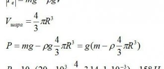
Let us apply the resulting expression for a spring of N turns with a diameter D (see Fig. 2). Moment of elastic forces Mz=F·D/2; spring length ℓ=πDN. Potential energy of an elastically deformed spring
U=\frac{Fx}{2}
Formula 8
Combining (7) and (8), we obtain a formula for determining the shear modulus using the spring stretching method
G=\frac{8FD^3N}{xd^4}
Formula 9
If you make a load oscillate on a spring, then by measuring the period of these oscillations, you can determine the shear modulus of the spring material. The period of weakly damped oscillations is almost equal to the period of free oscillations
T=2 \pi \sqrt{\frac{m}{k}}
k - spring stiffness
k=\frac {F}{x}
The shear modulus in this case will be calculated by the formula
G=\frac{32\pi NmD^3}{T^2d^4}
Formula 10
Laboratory installation FP-19, shown in Fig. 3, consists of a tripod 1, a bracket with a spring 2, a bracket with a photosensor 3, a set of replaceable weights 4.
Calculation of a compression spring made of rectangular wire.
The stiffness of a spring made of wire or a rectangular rod with the same dimensions as one made of round wire can be much greater. Accordingly, the compression force of the spring may be greater.
The program presented below is a revised version of the program for calculating cylindrical springs made of round wire , a detailed description of which you will find by following the link. Read this article and it will be easier for you to understand the algorithm.
may have guessed, is the determination of the coil stiffness ( C1 ) , which determines the spring stiffness ( C ) as a whole.
The following is a screenshot of the program and formulas for a cylindrical steel spring made of rectangular wire, in which ¾ of the turns are pressed at each end and the supporting surfaces are ground to ¾ of the circumference.
Attention!!!
After performing the calculation according to the program, check the tangential stresses!!!
4. I =( D1 / B) -1
5. At 1/3 : Y =5.3942*( H / B )2-0.3572*(H/B)+0.5272
At 1 : Y =5.4962*( H / B )(-1.715)
At 2< H / B <6 : Y = 3.9286 *( H / B )(- 1.2339 )
6. For H < B : C1 =(78500* H 4 )/( Y* ( D1 - B )3)
When H > B : C1 =(78500* B 4 )/( Y* ( D1 - B )3)
8. Tnom =1.25*( F2 / C1 )+H
9. Tmax =π*( D1 - B )*tg (10 ° )
11. S3 = T - H
12. F3 = C1 * S3
14. N calc =( L2 - H )/( H +F3 / C1 - F2 / C1 )
16.C = C1 / N
17. L0 = N * T + H
18. L3 = N * H + H
19. F2 = C * L0 - C * L2
21. F1 = C * L0 - C * L1
22. N1 = N +1.5
23. A =arctg ( T /( π *( D1 - H )))
24. L develop =π* N1 *( D1 - H )/cos ( A )
25. Q =H*B * Ldiv *7.85/106
Work order
Determination of the shear modulus by the spring stretching method
- Raise the bracket with the spring so that the bracket with the photosensor does not interfere with the measurements. Hang a mass of mass m1 on the spring. Using a ruler, note the location of the lower plane of the load x1.
- Hang a mass of mass m2 on the spring. Using a ruler, note the location of the bottom plane of the weight x2.
- Determine the elongation of the spring x = x1-x2.
- Using a caliper, measure the diameter of the spring D and the diameter of the rod from which the spring is made d.
- Determine the shear modulus using formula (9), in which F = mg is the force that stretches the spring, m = m2- m1, N is the number of turns in the spring.
Determination of shear modulus using a spring pendulum
- Hang one of the springs under study on the bracket. Hang a weight on the spring.
- Fix the bracket with a vertically suspended spring on a vertical stand in such a way that the stacked weight suspended from the spring, with its lower plane, coincides with the optical axis of the photosensor fixed in the lower part of the stand (the optical axis of the photosensor coincides with the marks on the photosensor).
- Press the “NETWORK” button of the unit. In this case, the display panel should turn on.
- Lift the weight up a little and release. In this case, the load begins to oscillate on the spring. Press the “START” button, determine the time value of 20 oscillations of the load using the timer.
- Press the "STOP" button.
- Determine the period of oscillation of the load using the formula:
T=\frac{t}{n}
t – oscillation time;
n – number of oscillations.
- Determine the shear modulus using formula (10)
Determine the relative error of shear modulus measurements carried out by various methods. Compare the values of the shear modulus obtained experimentally by different methods with the values given in the table on the installation. Draw a conclusion about the grade of steel from which the spring is made.
Modulus of elasticity of steel
►Elasticity modulus of steel
►Elasticity modulus of different steel grades
►Table of strength moduli of steel grades
►Elastic modulus for metals and alloys
►Elasticity of steels
►Strength limit
When designing steel products or structural elements, the ability of the alloy to withstand multidirectional types of loads is taken into account: impact, bending, tensile, compressive. The value of the elastic modulus of steel, along with hardness and other characteristics, shows resistance to these influences.
For example, in reinforced concrete construction, longitudinal and transverse reinforcing bars are used. In the horizontal plane they are subject to tension, and in the vertical plane they are subject to pressure from the entire mass of the structure. In places where stress is concentrated: corners, technological openings, elevator shafts and flights of stairs, more reinforcement is placed. The ability of concrete to absorb water causes constant changes in compressive and tensile loads.
Let's look at another example. During wartime, many developments in the field of aviation were created. The most common causes of accidents were engine fires. Taking off from the ground, the plane enters atmospheric layers with rarefied air and its body expands; the reverse process occurs during landing. In addition, the structure is affected by the resistance of air flows, the pressure of curved layers of air and other forces. Despite their strength, the alloys existing at that time were not always suitable for the manufacture of critical parts; this mainly led to ruptures of fuel tanks.
In various types of industry, parts of moving mechanisms are made from steel: springs, leaf springs. The grades used for such purposes are not prone to cracking under constantly changing loads.
Elastic modulus of different steel grades
Spring steel alloys have the greatest ability to resist deformation. These materials are characterized by high yield strength. The value shows the stress at which the deformation increases without external influences, for example, when bending and twisting.
The elasticity characteristics of steel depend on alloying elements and the structure of the crystal lattice. Carbon imparts hardness to the steel alloy, but in high concentrations it reduces ductility and springiness. The main alloying additives that increase elastic properties: silicon, manganese, nickel, tungsten.
Often, the desired indicators can be achieved only with the help of special heat treatment modes. In this way, all fragments of the part will have uniform fluidity indicators, and weak areas will be eliminated. Otherwise, the product may break, burst or crack. Grades 60G and 65G have such characteristics as tensile strength, viscosity, wear resistance, they are used for the manufacture of industrial springs and musical strings.
The metallurgical industry has created several hundred grades of steel with different elastic moduli. The table shows the characteristics of popular alloys.
Table of strength moduli of steel grades
| Name of steel | Young's modulus of elasticity, 10¹² Pa | Shear modulus G, 10¹² Pa | Modulus of bulk elasticity, 10¹² Pa | Poisson's ratio, 10¹²·Pa |
| Low carbon steel | 165…180 | 87…91 | 45…49 | 154…168 |
| Steel 3 | 179…189 | 93…102 | 49…52 | 164…172 |
| Steel 30 | 194…205 | 105…108 | 72…77 | 182…184 |
| Steel 45 | 211…223 | 115…130 | 76…81 | 192…197 |
| Steel 40Х | 240…260 | 118…125 | 84…87 | 210…218 |
| 65G | 235…275 | 112…124 | 81…85 | 208…214 |
| X12MF | 310…320 | 143…150 | 94…98 | 285…290 |
| 9ХС, ХВГ | 275…302 | 135…145 | 87…92 | 264…270 |
| 4Х5МФС | 305…315 | 147…160 | 96…100 | 291…295 |
| 3Х3М3Ф | 285…310 | 135…150 | 92…97 | 268…273 |
| R6M5 | 305…320 | 147…151 | 98…102 | 294…300 |
| P9 | 320…330 | 155…162 | 104…110 | 301…312 |
| P18 | 325…340 | 140…149 | 105…108 | 308…318 |
| R12MF5 | 297…310 | 147…152 | 98…102 | 276…280 |
| U7, U8 | 302…315 | 154…160 | 100…106 | 286…294 |
| U9, U10 | 320…330 | 160…165 | 104…112 | 305…311 |
| U11 | 325…340 | 162…170 | 98…104 | 306…314 |
| U12, U13 | 310…315 | 155…160 | 99…106 | 298…304 |
Modulus of elasticity for metals and alloys
| Name of material | Elastic modulus value, 10¹² Pa |
| Aluminum | 65-72 |
| Duralumin | 69-76 |
| Iron, carbon content less than 0.08% | 165-186 |
| Brass | 88-99 |
| Copper (Cu, 99%) | 107-110 |
| Nickel | 200-210 |
| Tin | 32-38 |
| Lead | 14-19 |
| Silver | 78-84 |
| Gray cast iron | 110-130 |
| Steel | 190-210 |
| Glass | 65-72 |
| Titanium | 112-120 |
| Chromium | 300-310 |
Elasticity of steels
| Name of steel | Elastic modulus value, 10¹² Pa |
| Low carbon steel | 165-180 |
| Steel 3 | 179-189 |
| Steel 30 | 194-205 |
| Steel 45 | 211-223 |
| Steel 40Х | 240-260 |
| 65G | 235-275 |
| X12MF | 310-320 |
| 9ХС, ХВГ | 275-302 |
| 4Х5МФС | 305-315 |
| 3Х3М3Ф | 285-310 |
| R6M5 | 305-320 |
| P9 | 320-330 |
| P18 | 325-340 |
| R12MF5 | 297-310 |
| U7, U8 | 302-315 |
| U9, U10 | 320-330 |
| U11 | 325-340 |
| U12, U13 | 310-315 |