Bending strength calculations
Of particular importance when designing structures and their individual elements are preliminary calculations of strength during bending.
Based on the results of the calculations, the actual (real) and permissible stresses that the elements and the entire structure as a whole can withstand are established. This will allow us to determine the real service life and develop recommendations for the correct operation of the developed object. This will allow us to determine the real service life and develop recommendations for the correct operation of the developed object.
The strength condition is derived by comparing two indicators. The highest stress that occurs in the cross section during operation and the permissible stress for a specific element. Strength depends on the material used, the size of the part, the processing method and its physical, mechanical and chemical properties.
To solve the problem, methods and mathematical apparatus developed in the disciplines of technical mechanics, materials science and strength of materials are used. In this case the following applies:
- Zhuravsky differential dependencies (a family of differential equations relating the main parameters during deformation and their derivatives);
- methods for determining displacement (Mohr's method and Vereshchagin's rule are considered the most effective);
- family of accepted hypotheses;
- developed rules for constructing graphic images (constructing diagrams).
The parameters are calculated in three stages:
- during verification calculations (calculate the value of the maximum voltage);
- at the design stage (the thickness and cross-section parameters of the beam are selected);
- when calculating the permissible load.
The resulting signs of the stress values are determined based on an assessment of the ongoing physical processes and the direction of the projections of the vectors of forces and moments.
The most visual results of the calculation are the constructed diagrams on the surface of the product being developed. They reflect the influence of all force factors on the various layers of parts. With pure bending, the diagrams have the following features:
- in the section of the beam under study with no load, which is distributed in nature, the diagram is depicted as a straight line;
- in the area where the so-called concentrated forces are applied, the diagram shows a change in direction in the form of a jump in the place to which the force vector is applied;
- at the point of appearance of the applied torque, the jump is equal to the value of this parameter;
- in a section with a distributed load, the intensity of the impact changes according to a linear law, and the transverse loads have a power-law change (most often along a parabolic curve, with the direction of convexity towards the applied load);
- within the boundaries of the studied area, the bending moment function acquires an extremum (based on methods for studying functions using differential calculus, it is possible to establish the nature of the extremum - maximum or minimum).
In practice, solving systems of differential equations can cause certain difficulties. Therefore, during calculations, some forgiveness is allowed, which does not affect the accuracy of the determined parameters. These simplifications include:
- the calculation is made taking into account normal stresses;
- the hypothesis of plane sections is accepted as the main assumption;
- longitudinal fibers do not produce additional pressure between themselves (this allows us to assume that the bending processes are linear);
- the deformation of the fibers does not depend on their width (the normal stress values are constant over the entire width);
- for the design beam, one symmetry plane is specified (all external forces lie in this plane);
- the physical and mechanical characteristics of the material obey Hooke’s law (the elastic modulus has a constant value);
- processes in the beam obey the laws of plane bending (this assumption follows from the relationships between the geometric dimensions of the product).
Modern methods of studying the influence of external forces, internal stresses and moments make it possible to calculate with a high degree of accuracy the strength of each part and the entire structure as a whole. The use of computer calculation methods, fractal geometry and 3D graphics allows us to obtain a detailed picture of the processes taking place.
Hooke's law
Observations of various types of deformation have shown that the amount of deformation of a body depends on the mechanical stress arising under the influence of forces applied to the body.
This dependence is described by a law discovered in 1660 by the English scientist Robert Hooke, who is called one of the fathers of experimental physics.
It is convenient to consider types of deformation on a beam model. This is a body, one of the three sizes of which (width, height or length) is much larger than the other two. Sometimes, instead of the term “beam”, the term “rod” is used. The length of the rod is much greater than its width and height.
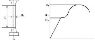
Let us consider this relationship for tensile-compressive strain.
Let us assume that the rod initially has length L. Under the action of external forces, its length will change by ∆l. It is called absolute elongation (compression) of the rod.
For tensile-compressive deformation, Hooke's law has the form:
F – force compressing or stretching the rod; k – elasticity coefficient.
The elastic force is directly proportional to the elongation of the body to a certain limiting value.
E – elastic modulus of the first kind or Young’s modulus. Its value depends on the properties of the material. This is a theoretical quantity introduced to characterize the elastic properties of bodies.
S
– cross-sectional area of the rod.
The ratio of absolute elongation to the original length of the rod is called relative elongation or relative deformation.
When stretched, its value is positive, and when compressed, it is negative.
The ratio of the external force modulus to the cross-sectional area of the rod is called mechanical stress.
Then Hooke's law for relative quantities will look like this:
The stress σ is directly proportional to the relative strain ε.
It is believed that the force tending to lengthen the rod is positive (F ˃ 0), and the force shortening it is negative (F ˂ 0).
Further reading[edit]
- Bazant, Zdenek P.; Sedolin, Luigi (2010). Three-dimensional continuum instabilities and finite strain tensor effects, Chapter 11 in Stability of Structures, 3rd ed. Singapore, NJ, London: World Scientific Publishing. ISBN 9814317039.
- Dill, Ellis Harold (2006). Continuum mechanics: elasticity, plasticity, viscoelasticity. Germany: CRC Press. ISBN 0-8493-9779-0.
- Hutter, Columbanus; Jonck, Klaus (2004). Continuum methods of physical modeling. Germany: Springer. ISBN 3-540-20619-1.
- Jirasek, M; Bazant, Z. P. (2002). Inelastic Analysis of Structures. London and New York: J. Wiley & Sons. ISBN 0471987166.
- Lubarda, Vlado A. (2001). Theory of elastic-plasticity. CRC Press. ISBN 0-8493-1138-1.
- Macosko, C. W. (1994). Rheology: principles, measurements and applications
. HF Publishers. ISBN 1-56081-579-5. - Mace, George E. (1970). Continuum mechanics. McGraw-Hill Professional. ISBN 0-07-040663-4.
- Mace, J. Thomas; Mace, George E. (1999). Continuum mechanics for engineers (2nd ed.). CRC Press. ISBN 0-8493-1855-6.
- Nemat-Nasser, Sia (2006). Plasticity: a treatise on the finite deformation of heterogeneous inelastic materials. Cambridge: Cambridge University Press. ISBN 0-521-83979-3.
- Prager, William (1961). Introduction to Continuum Mechanics. Boston: Ginn and Co. ISBN. 0486438090.
| Authoritative control |
|
Basic Concepts
Torsion is understood as a type of deformation characteristic of the conditions under which a force is applied to a body in a transverse plane. As a result, a torque is generated in the cross section. Shafts and springs are subject to torsional deformations.
A shaft is a torsionally rotating part in the form of a rod.
A torsion bar is understood as a rod that functions in torsion and is used as an elastic element.
For round shafts, which are most widely used in technology, a theory of torsion has been developed. It is based on three provisions:
- After deformation, the flat cross-section of the part is maintained.
- During deformation, the radii passing across the part do not bend and rotate at an equal angle.
- When deformed, the longitudinal fibers retain their dimensions, therefore, the distances separating the cross sections remain unchanged.
From the above provisions it follows that torsion is represented by the shear deformation of the material between adjacent cross sections, caused by the rotation of the latter around an axis.
Torsional deformations are considered to be the mutual rotation of sections. They are formed due to the action of pairs of forces on the rod with planes of action perpendicular to its longitudinal axis.
The angle of twist of a rod of a cylindrical configuration within the boundaries of elastic deformations is determined by the equation of Hooke's law for torsion, which represents the ratio of the product of the moment and the length of the shaft to the product of the geometric polar inertial moment and the shear modulus.
The relative twist angle is calculated as the quotient of the twist angle and the length of the rod.
Rotating or twisting moments are understood as indicators of pairs of forces acting on the shaft. They are divided into external, called rotating and twisting, and internal (torsional). Under the influence of external torques perpendicular to the longitudinal axis of the beam, internal ones are formed. They are transmitted to the part at the installation points of belt pulleys, gears, etc.
Torque is represented by a force factor that causes or impedes the circular movement of a section relative to an axis perpendicular to it. Its value is equal to the sum of the twisting forces on one side of a given point. Internal moments directed counterclockwise from the external normal (rejected part) are considered positive. In this case, the corresponding external moment has a direction coinciding with the clockwise direction.
Strength and rigidity conditions are used to solve the following problems:
- Performing verification calculations of these conditions for specific torque values and shafts of a certain size and material.
- Perform design calculations to calculate diameters and find the largest one.
- Determining the load capacity of a shaft by calculating the torque from both conditions and finding the smaller of them.
A torque diagram is a graph that displays the law of their change along the length or cross-section of a part.
When dividing a part along its length into three sections in accordance with the section method, it turns out that for the first (right) fragment there is a linear dependence of the torque on the cross-section coordinate due to the influence of a uniformly distributed load; for the second and third sections this dependence is absent. In this case, at the points of application of external concentrated forces, jumps corresponding to their magnitude are observed.
A linear change is observed in the section, determined by the law of tangential stresses, in direct proportion to the distance from the center.
The polar section moment of inertia is a geometric characteristic of the torsional stiffness for a circular shaft. The polar moment of resistance of a section is a similar parameter for its strength.
It should be noted that most of the above concepts are described using formulas.
Torsion
If the types of mechanical deformations were divided according to the complexity of calculations, then this one would take first place. This type of change in the shape of a body occurs when two forces act on it. In this case, the displacement of any point of the body occurs perpendicular to the axis of the acting forces. Speaking about this type of deformation, the following quantities to be calculated should be mentioned:
- F is the angle of twist of the cylindrical rod.
- T is the moment of action.
- L is the length of the rod.
- G is the moment of inertia.
- F is the shear modulus.
The formula looks like this:
F=(T*L)/(G*F).
Another quantity that requires calculation is the relative twist angle:
Q=F/L (values are taken from the previous formula).
Hooke's law
Observations of various types of deformation have shown that the amount of deformation of a body depends on the mechanical stress arising under the influence of forces applied to the body.
This dependence is described by a law discovered in 1660 by the English scientist Robert Hooke, who is called one of the fathers of experimental physics.
It is convenient to consider types of deformation on a beam model. This is a body, one of the three sizes of which (width, height or length) is much larger than the other two. Sometimes, instead of the term “beam”, the term “rod” is used. The length of the rod is much greater than its width and height.
Let us consider this relationship for tensile-compressive strain.
Let us assume that the rod initially has length L. Under the action of external forces, its length will change by ∆l. It is called absolute elongation (compression) of the rod.
For tensile-compressive deformation, Hooke's law has the form:
F is the force compressing or stretching the rod; k is the elasticity coefficient.
The elastic force is directly proportional to the elongation of the body to a certain limiting value.
E is the elastic modulus of the first kind or Young’s modulus. Its value depends on the properties of the material. This is a theoretical quantity introduced to characterize the elastic properties of bodies.
S
- cross-sectional area of the rod.
The ratio of absolute elongation to the original length of the rod is called relative elongation or relative deformation.
When stretched, its value is positive, and when compressed, it is negative.
The ratio of the external force modulus to the cross-sectional area of the rod is called mechanical stress.
Then Hooke's law for relative quantities will look like this:
The stress σ is directly proportional to the relative strain ε.
It is believed that the force tending to lengthen the rod is positive (F ˃ 0), and the force shortening it is negative (F ˂ 0).
Definition and overview of shear deformation
The main feature characterizing shear deformation is the preservation of constant volume. Regardless of the direction in which the force factors act, this parameter remains unchanged.
Examples of shear deformation can be found during various types of work. Such cases include:
- when sawing timber;
- cutting or chopping metal;
- as a result of violation of the integrity of the fastening of metal or wooden parts connected by hardware;
- beams in places where supports are attached;
- places where bridge spans are fastened;
- fasteners on the jumpers for connecting railway rails;
- cutting a sheet of paper with scissors.
Under certain conditions, a net shift occurs. It is defined as a shear in which all four faces (for example, a rectangular part) are affected only by stresses directed tangentially to the surface. In this case, there will be a smooth shift of all layers of the part from the upper to the lower layers. Then the external force changes the shape of the part, but the volume remains unchanged.
To assess the magnitude of the shift and the reliability of the structure, the following parameters are used:
- magnitude, direction and point of application of the acting force;
- shear modulus;
- angle of change of the external edges of the product;
- tangential stress;
- torsion modulus (depends on the physical and mechanical characteristics of the material);
Calculation and practical measurement of these parameters are necessary to assess the stability and integrity of the structure. The formula that allows you to calculate permissible changes takes into account all the impacts on specific layers of the part and the entire structure as a whole.
In the case of deformation, the angle is considered proportional to the external force. Increasing the degree of impact can transform the shear deformation into shearing. This will lead to the destruction of not only the fastening elements (bolts, studs, rivets), but also the entire part.
For clarity, the change in the shape of a part during shear deformation is indicated by the dynamics of the process using the magnitude of the displacement angle and the vectors of the resulting stresses. The acting force is directed towards the displacement of the layers of the part under consideration.
In modern conditions, the shear angle is measured by various technical instruments. The main device for measuring displacement parameters is a strain gauge. These devices operate on different physical principles:
- optical (including laser);
- acoustic;
- X-ray; electrical;
- pneumatic.
In these devices, the relative shear deformation is processed using modern computing facilities using appropriate software. Each method has its own advantages and disadvantages. Their use depends on the task at hand, technical and financial feasibility.
Description of deformation[edit]
Warp is a change in the metric properties of a continuous body, meaning that the curve drawn when the body is initially placed changes in length as it moves to the curve when it is finally placed. If none of the curves changes length, a rigid body displacement is said to have occurred.
It is convenient to define a reference configuration or initial geometric state of a continuum body from which all subsequent configurations will be referenced. The reference configuration does not have to be the one that the body will ever actually occupy. Often the configuration at t
= 0 is considered the reference configuration
κ
0 (
B
) .
The configuration at the current moment t is the current configuration
.
For deformation analysis, the reference configuration is defined as the undeformed configuration
, and the current configuration is like
the deformed configuration
. In addition, time is not taken into account in the deformation analysis, so the sequence of configurations between the undeformed and deformed configurations is not of interest.
The components X
i
of the position vector
X
of the particle in the reference configuration, taken relative to the reference coordinate system, are called
material or reference coordinates
.
On the other hand, the components x i
of the position vector
x
of a particle in a deformed configuration, taken relative to a spatial reference system, are called
spatial coordinates
. There are two methods for analyzing the deformation of a continuum. One description is made in terms of material or reference coordinates, and this is called a material description or Lagrangian description. The second description of the deformation is made in terms of spatial coordinates, it is called the spatial description or Eulerian description.
When a solid body deforms, there is continuity in the sense that:
- Material points that form a closed curve at any time will always form a closed curve at any subsequent time.
- Material points forming a closed surface at any time will always form a closed surface at any subsequent time, and matter inside a closed surface will always remain inside.
Affine deformation[edit]
A deformation is called an affine deformation if it can be described by an affine transformation. Such a transformation consists of a linear transformation (such as rotation, shear, stretching and compression) and rigid body translation. Affine deformations are also called homogeneous deformations. [8]
Therefore, the affine deformation has the form
x ( X , t ) = F ( t ) ⋅ X + c ( t ) {\displaystyle \mathbf {x} (\mathbf {X} ,t)={\boldsymbol {F}}(t)\cdot \mathbf {X} +\mathbf {c} (t)}
where x
is the position of the point in the deformed configuration,
X
is the position in the reference configuration, t is the time parameter,
F
is the linear transducer, and
c
is the translation.
In matrix form, where the components are relative to an orthonormal basis, [ x 1 ( X 1 , X 2 , X 3 , t ) x 2 ( X 1 , X 2 , X 3 , t ) x 3 ( X 1 , X 2 , X 3, t)] = [F 11 (t) F 12 (t) F 13 (t) F 21 (t) F 22 (t) F 23 (t) F 31 (t) F 32 (t) F 33 ( t ) ] [ X 1 X 2 X 3 ] + [ c 1 ( t ) c 2 ( t ) c 3 ( t ) ] {\displaystyle {\begin{bmatrix}x_{1}(X_{1},X_{ 2},X_{3},t)\\x_{2}(X_{1},X_{2},X_{3},t)\\x_{3}(X_{1},X_{2} ,X_{3},t)\end{bmatrix}}={\begin{bmatrix}F_{11}(t)&F_{12}(t)&F_{13}(t)\\F_{21}(t )&F_{22}(t)&F_{23}(t)\\F_{31}(t)&F_{32}(t)&F_{33}(t)\end{bmatrix}}{\begin{bmatrix} X_{1}\\X_{2}\\X_{3}\end{bmatrix}}+{\begin{bmatrix}c_{1}(t)\\c_{2}(t)\\c_{3 }(t)\end{bmatrix}}}
The above deformation becomes non-affine
or
inhomogeneous
if
F
=
F
(
X
,
t
) or
c
=
c
(
X
,
t
).
Rigid body motion[edit]
Rigid body motion is a special affine deformation that does not include shear, stretching, or compression. Transformation matrix F
is its own orthogonal to allow rotation but no reflections.
The motion of a rigid body can be described as follows:
x ( X , t ) = Q ( t ) ⋅ X + c ( t ) {\displaystyle \mathbf {x} (\mathbf {X} ,t)={\boldsymbol {Q}}(t)\cdot \mathbf {X} +\mathbf {c} (t)}
Where
Q ⋅ QT = QT ⋅ Q = 1 {\displaystyle {\boldsymbol {Q}}\cdot {\boldsymbol {Q}}^{T}={\boldsymbol {Q}}^{T}\cdot {\boldsymbol { Q}}={\boldsymbol {\mathit {1}}}}
In matrix form
[ x 1 ( X 1 , X 2 , X 3 , t ) x 2 ( X 1 , X 2 , X 3 , t ) x 3 ( X 1 , X 2 , X 3 , t ) ] = [ Q 11 ( t ) Q 12 ( t ) Q 13 ( t ) Q 21 ( t ) Q 22 ( t ) Q 23 ( t ) Q 31 ( t ) Q 32 ( t ) Q 33 ( t ) ] [ X 1 X 2 X 3 ] + [ c 1 ( t ) c 2 ( t ) c 3 ( t ) ] {\displaystyle {\begin{bmatrix}x_{1}(X_{1},X_{2},X_{3},t)\ \x_{2}(X_{1},X_{2},X_{3},t)\\x_{3}(X_{1},X_{2},X_{3},t)\end{ bmatrix}}={\begin{bmatrix}Q_{11}(t)&Q_{12}(t)&Q_{13}(t)\\Q_{21}(t)&Q_{22}(t)&Q_{23 }(t)\\Q_{31}(t)&Q_{32}(t)&Q_{33}(t)\end{bmatrix}}{\begin{bmatrix}X_{1}\\X_{2}\ \X_{3}\end{bmatrix}}+{\begin{bmatrix}c_{1}(t)\\c_{2}(t)\\c_{3}(t)\end{bmatrix}}}
Strength and deformation
Despite the diversity of the living and inanimate world, despite the creation by man of numerous material objects, all objects and living beings have a common property - strength. It is commonly understood as the ability of a material to be preserved over a long period of time without visible destruction. There is strength of structures, molecules, structures. This characteristic is appropriate for blood vessels, human bones, brick column, glass, water. Shear deformation is an option for testing a structure for strength.
The use of different types of deformations by humans has deep historical roots. It all started with the desire to connect a stick and a sharp tip together in order to hunt ancient animals. Already in those distant times, people were interested in deformation. Shift, compression, stretching, and bending helped him create homes, tools, and prepare food. With the development of technology, humanity has managed to use various types of deformations so that they bring significant benefits.
Shear stress
The influence of an external force on the edge leads to a change in shape in the product. All stresses are divided into two categories: normal and tangential. Internal stresses that arise in various layers of a product subject to deformation are considered normal.
Shear stresses and strains are described using analytical expressions and graphical representations. The general state is described by spatial (three-coordinate) stress. If in a particular case it is possible to identify sections in which both types of stresses are equal to zero, we can move on to simpler models for describing this process. They are a two-coordinate (flat) stress state or a linear one. The last two models are special cases of a three-coordinate stress state.
Classification
In general, the following types of deformation can be distinguished: elastic and inelastic. Elastic, or reversible, deformations disappear after the force acting on them disappears. The basis of this physical law is used in strength training equipment, for example, in the expander. If we talk about the physical component, then it is based on the reversible displacement of atoms - they do not go beyond the limits of interaction and the framework of interatomic bonds.
Inelastic (irreversible) deformations, as you understand, are the opposite process. Any force applied to the body leaves marks/deformation. This type of impact also includes the deformation of metals. With this type of shape change, other properties of the material can often change as well. For example, deformation caused by cooling may increase the strength of the product.
Types of deformation
Depending on how the external force is applied, strains of tension-compression, shear, bending, and torsion are distinguished.
Tension-compression deformation
Tensile-compressive deformation is caused by forces that are applied to the ends of the beam parallel to its longitudinal axis and directed in different directions.
Under the influence of external forces, particles of a solid substance, oscillating relative to their equilibrium position, are displaced. But internal forces of interaction between particles are trying to interfere with this process, trying to keep them in their original position at a certain distance from each other. The forces that prevent deformation are called elastic forces.
Tensile deformation is experienced by a stretched bowstring, a tow rope of a car during towing, coupling devices of railway cars, etc.
When we climb the stairs, the steps are deformed under the influence of our gravity. This is a compression deformation. The same deformation is experienced by the foundations of buildings, columns, walls, and the pole with which the athlete jumps.
Shear deformation
If an external force is applied tangentially to the surface of a block, the lower part of which is fixed, then shear deformation occurs. In this case, the parallel layers of the body seem to shift relative to each other.
Let's imagine a rickety stool standing on the floor. Let's apply a force tangentially to its surface, that is, we'll simply pull the upper part of the stool towards ourselves. All its planes, parallel to the floor, will shift relative to each other at the same angle.
The same deformation occurs when a sheet of paper is cut with scissors, a wooden beam is sawed with a saw with sharp teeth, etc. All fasteners connecting surfaces - screws, nuts, etc. - are subject to shear deformation.
Bending deformation
This deformation occurs if the ends of a beam or rod rest on two supports. In this case, it is subject to loads perpendicular to its longitudinal axis.
All horizontal surfaces placed on vertical supports experience bending deformation. The simplest example is a ruler lying on two books of the same thickness. When we put something heavy on top of it, it will bend. In the same way, a wooden bridge spanning a stream bends when we walk along it.
Torsional deformation
Torsion occurs in a body if a couple of forces are applied to its cross section. In this case, the cross sections will rotate around the axis of the body and relative to each other. Such deformation is observed in rotating machine shafts. If you manually wring out (twist) wet laundry, it will also be subject to torsional deformation.
Offset [edit]
Rice. 1. Movement of a solid body.
Changing the configuration of a solid body results in displacement. Body displacement consists of two components: rigid body displacement and strain. Rigid body displacement consists of simultaneously moving and rotating a body without changing its shape or size. Deformation implies a change in the shape and/or size of a body from its original or undeformed configuration κ
0 (
B
) to the current or deformed configuration
κ t
(
B
) (Figure 1).
If after continuum displacement there is a relative displacement between particles, deformation has occurred. On the other hand, if after the continuum has shifted, the relative displacement between the particles in the current configuration is zero, then there is no deformation, and a rigid body displacement is said to have occurred.
Vector connecting the positions of particle P
in the undeformed configuration and the deformed configuration, is called the displacement vector
u (
X
,
t
)
=
u i e i
description , or
U
(
x
,
t
) =
UJEJ Eulerian
description.
Offset field
represents the vector field of all displacement vectors for all particles in the body, which relates the deformed configuration to the undeformed configuration.
It is convenient to analyze the deformation or motion of a solid body in terms of the displacement field. In general, the displacement field is expressed in terms of material coordinates as u ( X , t ) = b ( X , t ) + x ( X , t ) − X or ui = α i J b J + xi − α i JXJ {\displaystyle \ \mathbf {u} (\mathbf {X} ,t)=\mathbf {b} (\mathbf {X} ,t)+\mathbf {x} (\mathbf {X} ,t)-\mathbf {X} \qquad {\text{or}}\qquad u_{i}=\alpha _{iJ}b_{J}+x_{i}-\alpha _{iJ}X_{J}}
or in terms of spatial coordinates as
U ( x , t ) = b ( x , t ) + x − X ( x , t ) or UJ = b J + α J ixi − XJ {\displaystyle \\mathbf {U} (\mathbf {x} ,t )=\mathbf {b} (\mathbf {x} ,t)+\mathbf {x} -\mathbf {X} (\mathbf {x} ,t)\qquad {\text{or}}\qquad U_{ J}=b_{J}+\alpha _{Ji}x_{i}-X_{J}\,}
where α Ji
are direction cosines between the material and spatial coordinate systems with unit vectors
E J
and
e i
, respectively.
Thus EJ ⋅ ei = α J i = α i J {\displaystyle \ \mathbf {E} _{J}\cdot \mathbf {e} _{i}=\alpha _{Ji}=\alpha _{iJ }}
and the relationship between ui
and
U J
is determined by the expression
ui = α i JUJ or UJ = α J iui {\displaystyle \u_{i}=\alpha _{iJ}U_{J}\qquad {\text{or}}\qquad U_{J}= \alpha _{Ji}u_{i}}
I know this
ei = α i JEJ {\displaystyle \ \mathbf {e} _{i}=\alpha _{iJ}\mathbf {E} _{J}}
Then
u ( X , t ) = uiei = ui ( α i JEJ ) = UJEJ = U ( x , t ) {\displaystyle \mathbf {u} (\mathbf {X} ,t)=u_{i}\mathbf {e } _{i}=u_{i}(\alpha _{iJ}\mathbf {E} _{J})=U_{J}\mathbf {E} _{J}=\mathbf {U} (\mathbf {x} ,t)}
Typically, the coordinate systems for the undeformed and deformed configurations are superimposed on each other, resulting in b
= 0, and the direction cosines become Kronecker deltas:
EJ ⋅ ei = δ J i = δ i J {\displaystyle \\mathbf {E} _{J}\cdot \mathbf {e} _{i}=\delta _{ Ji}=\delta _{iJ}}
Thus we have
u ( X , t ) = x ( X , t ) − X or ui = xi − δ i JXJ = xi − X i {\displaystyle \\mathbf {u} (\mathbf {X} ,t)=\mathbf { x} (\mathbf {X} ,t)-\mathbf {X} \qquad {\text{or}}\qquad u_{i}=x_{i}-\delta _{iJ}X_{J}=x_ {i}-X_{i}}
or in terms of spatial coordinates as
U ( x , t ) = x − X ( x , t ) or UJ = δ J ixi − XJ = x J − XJ {\displaystyle \\mathbf {U} (\mathbf {x} ,t)=\mathbf { x} -\mathbf {X} (\mathbf {x} ,t)\qquad {\text{or}}\qquad U_{J}=\delta _{Ji}x_{i}-X_{J}=x_ {J}-X_{J}}
Displacement gradient tensor[edit]
Partial differentiation of the displacement vector with respect to material coordinates gives the material displacement gradient tensor
∇ X u
. Thus we have:
| u ( X , t ) = x ( X , t ) − X ∇ X u = ∇ X x − I ∇ X u = F − I {\displaystyle {\begin{aligned}\mathbf {u} (\mathbf {X } ,t)&=\mathbf {x} (\mathbf {X} ,t)-\mathbf {X} \\\nabla _{\mathbf {X} }\mathbf {u} &=\nabla _{\ mathbf {X} }\mathbf {x} -\mathbf {I} \\\nabla _{\mathbf {X} }\mathbf {u} &=\mathbf {F} -\mathbf {I} \\\end {aligned}}} | or | ui = xi − δ i JXJ = xi − X i ∂ ui ∂ XK = ∂ xi ∂ XK − δ i K {\displaystyle {\begin{aligned}u_{i}&=x_{i}-\delta _{iJ }X_{J}=x_{i}-X_{i}\\{\frac {\partial u_{i}}{\partial X_{K}}}&={\frac {\partial x_{i}} {\partial X_{K}}}-\delta _{iK}\\\end{aligned}}} |
where F
—
strain gradient tensor
.
Similarly, partial differentiation of the displacement vector with respect to the spatial coordinates gives the spatial displacement of the gradient tensor
∇ x
U. Thus we have
| U ( x , t ) = x − X ( x , t ) ∇ x U = I − ∇ x X ∇ x U = I − F − 1 {\displaystyle {\begin{aligned}\mathbf {U} (\mathbf {x} ,t)&=\mathbf {x} -\mathbf {X} (\mathbf {x} ,t)\\\nabla _{\mathbf {x} }\mathbf {U} &=\mathbf { I} -\nabla _{\mathbf {x} }\mathbf {X} \\\nabla _{\mathbf {x} }\mathbf {U} &=\mathbf {I} -\mathbf {F} ^{ -1}\\\end{aligned}}} | or | UJ = δ J ixi − XJ = x J − XJ ∂ UJ ∂ xk = δ J k − ∂ XJ ∂ xk {\displaystyle {\begin{aligned}U_{J}&=\delta _{Ji}x_{i} -X_{J}=x_{J}-X_{J}\\{\frac {\partial U_{J}}{\partial x_{k}}}&=\delta _{Jk}-{\frac { \partial X_{J}}{\partial x_{k}}}\\\end{aligned}}} |
Compression and stretching
Tensile strain is associated with relative or absolute elongation of the body. An example is a homogeneous rod that is fixed at one end. When a force acting in the opposite direction is applied along the axis, a stretching of the rod is observed.
The force applied towards the fixed end of the rod leads to compression of the body. In the process of compression or stretching, a change in the cross-sectional area of the body occurs.
Tensile deformation is a change in the state of an object, accompanied by displacement of its layers. This type can be analyzed on a model of a solid body consisting of parallel plates that are connected to each other by springs. Due to the horizontal force, the plates are shifted by a certain angle, but the volume of the body does not change. In the case of elastic deformations, a directly proportional relationship was revealed between the force applied to the body and the shear angle.
CONTENT
- 1 strain 1.1 Deformation measures 1.1.1 Engineering load
- 1.1.2 Tension factor
- 1.1.3 True voltage
- 1.1.4 Green strain
- 1.1.5 Almansi strain
- 1.2.1 Normal deformation
- 2.1 Affine deformation
- 3.1 Displacement gradient tensor
- 4.1 Plane strain 4.1.1 Strain of an isochoric plane
Deformations using the example of the human body
The human body is subjected to serious mechanical stress from its own efforts and weight that appears during physical activity. In general, deformation (shear) is characteristic of the human body:
- The spine, feet, and lower limbs experience compression.
- Ligaments, upper limbs, muscles, and tendons are stretched.
- The bend is characteristic of the limbs, pelvic bones, and vertebrae.
- The neck is subjected to torsion during rotation, and the hands experience it during rotation.
But if the maximum stress is exceeded, rupture is possible, for example, in the bones of the shoulder and hip. In ligaments, the tissues are connected so elastically that they can be stretched twice. By the way, shear deformation explains the danger of women walking in high heels. The body weight will be transferred to the fingers, which will double the load on the bones.
According to the results of medical examinations conducted in schools, only one out of ten children can be considered healthy. How are deformities related to children's health? Shift, torsion, and compression are the main causes of poor posture in children and adolescents.
Strength and deformation
Despite the diversity of the living and inanimate world, despite the creation by man of numerous material objects, all objects and living beings have a common property - strength. It is commonly understood as the ability of a material to be preserved over a long period of time without visible destruction. There is strength of structures, molecules, structures. This characteristic is appropriate for blood vessels, human bones, brick column, glass, water. Shear deformation is an option for testing a structure for strength.
The use of different types of deformations by humans has deep historical roots. It all started with the desire to connect a stick and a sharp tip together in order to hunt ancient animals. Already in those distant times, people were interested in deformation. Shift, compression, stretching, and bending helped him create homes, tools, and prepare food. With the development of technology, humanity has managed to use various types of deformations so that they bring significant benefits.
Hooke's law
Mathematical calculations necessary in construction and technology made it possible to apply Hooke's law to shear deformation. The formula showed a direct relationship between the force applied to the body and its elongation (compression). Hooke used the coefficient of rigidity, showing the relationship between a material and its ability to deform.
With the development and improvement of technical means, apparatus and instruments, and the development of the theory of resistance, serious studies of plasticity and elasticity were carried out. The results of the fundamental experiments began to be used in construction technology, the theory of structures, and theoretical mechanics.
Thanks to an integrated approach to problems associated with various types of deformation, it was possible to develop the construction industry and prevent correct posture in the country's younger generation.
Links[edit]
- Truesdell, C.; Noll, W. (2004). Nonlinear field theories of mechanics
(3rd ed.). Springer. paragraph 48. - Wu, H.-C. (2005). Continuum mechanics and plasticity
. CRC Press. ISBN 1-58488-363-4. - Lubliner, Jacob (2008). Theory of Plasticity (PDF) (Revised ed.). Dover Publications. ISBN 0-486-46290-0. Archived from the original (PDF) on March 31, 2010.
- ^ ab Rees, David (2006). Basic Engineering Plasticity: An Introduction to Engineering and Manufacturing Applications. Butterworth-Heinemann. ISBN 0-7506-8025-3. Archived from the original on December 22, 2017.
- ↑
"Earth". Encyclopædia Britannica from the Encyclopædia Britannica 2006 Ultimate Reference Suite DVD [2009]. - Rees, David (2006). Basic Engineering Plasticity: An Introduction to Engineering and Manufacturing Applications. Butterworth-Heinemann. paragraph 41. ISBN 0-7506-8025-3. Archived from the original on December 22, 2022.
- Henkey, H. (1928). "Improved Form of Elasticity of Elastic Elements of an Ideal Elastic Material." Zeitschrift für technische Physik
.
9
: 215–220. - ^ abc Ogden, R. W. (1984). Nonlinear elastic deformations
. Dover.