A huge number of household and industrial items that we use every day are made on CNC machines.
The tandem of a computer and a processing center made it possible to make serial and mass production more accurate and at the same time reduce the cost of its products. The CNC system of a modern machine tool is a complex hardware and software complex that is responsible for the synchronized operation of all its actuators.
Automated control has brought production equipment to a whole new level. The CNC control system in the case of a single machine can significantly expand its production capabilities: increase the range of products produced, increase the complexity of processing.
No machine operator will be able to control the simultaneous movement along three axes, as well as the rotation and tilt of the spindle head. Fully automated control copes with this task without difficulty. It allows you to build complex technological lines that perform the full cycle of operations “blank - finished product”, based on one universal machine or several pieces of equipment.
Take the test
Repair, maintenance and modernization of metal-cutting equipment
Regardless of its design and type, equipment for cutting and processing metals is subject to regular preventive maintenance and repair.
Repair of metal-cutting equipment can be divided into several types:
- current.
Elimination of minor breakdowns by specialists in production, without the involvement of third parties and with minimal interruptions in work; - average.
Standard measures that are aimed at replacing main and auxiliary functional blocks. The repair complexity of metal-cutting equipment is determined by the type of machine and its design. Depending on this criterion, work can be carried out both directly at the workplace and in specially designated premises (workshops); - capital.
The most complex and time-consuming type of repair, which requires the presence of specialists (craftsmen from the equipment manufacturer who have undergone special training). During a major overhaul, worn-out parts of the equipment are completely replaced for its full, uninterrupted operation in the future.
The standards for the repair of metal-cutting equipment are given in GOSTs and in the accompanying documents. Depending on the type and variety of machines, standards may vary slightly.
To successfully complete the assigned tasks and organize trouble-free operation, not only regular maintenance of metal-cutting equipment is carried out, but also a set of measures to modernize it.
A large number of manufacturers have tried to make their products unified, incorporating the possibility of improvement into their design.
Modernization of metal-cutting equipment is an integral procedure in any modern enterprise. In most cases we are talking about CNC machines. Special service organizations are engaged in various types of repairs and modernization of equipment.
His Majesty the computer needs a program
Unlike a standard personal computer, which is a universal device for processing information and is capable of working with any data presented in digital form, the microprocessor used in the design of many CNC machines is a specialized device. It does not contain anything superfluous, and its entire set of functions is designed to perform the main task - monitoring the state of all executive bodies of the machine and controlling their work according to a special program. To control particularly complex modern machines, more productive and multitasking devices are used - industrial computers.
One of the most important characteristics that allows us to judge the performance and technical capabilities of the machine and the system that controls its operation is the number of “axes”. In other words, channels of interaction with the object, controlled parameters. However, in any case, regardless of the microprocessor of what level of complexity and architecture is installed in a given control controller, a previously prepared program is needed for its operation. In which all actions of the CNC machine mechanisms necessary for the manufacture or processing of the required part must be accurately and consistently described.
When operating CNC machines, two types of programs are used:
● System (utility) programs that are stored in ROM (read-only memory of the system). They provide the initial stage of operation of the controller after switching on, are responsible for setting up the machine and the entire CNC system, its ability to understand operator commands and interact with external devices.
● Controllers – external programs. Contain a set of commands and instructions for the executive bodies of the machine. Control programs (CP) can be entered into the controller step by step by the operator, input from external storage media is possible, and in modern systems programs can come directly from the computers of software developers through the enterprise computer network.
Having replaced a person who, before the era of CNC machines, successfully coped with the production of the necessary parts, a programmable control unit, also known as a controller, must provide the required result, step by step turning on and off the movement mechanisms of the table, workpiece and tool magazine, changing rotation modes or speed translational movement of the workpiece. As a result of executing the program, a part should be obtained that fully corresponds to the specifications in terms of size and surface finish.
The companies that were at the forefront of the development and production of CNC systems initially programmed their machines using their own specially designed commands. If, with this approach, CNC machines from different manufacturers were put into production, preparing programs for their operation would be a difficult task. To try to ensure software and technical compatibility of equipment from different brands, the language for creating programs for CNC machines was unified.
The basic control code for preparing programs was a set of commands developed by specialists from the Electronic Industries Alliance in the 60s of the last century. This is the so-called “G” and “M” code language, which is more often called simply G-code. The designations of preparatory and main functions adopted in this language begin with the Latin letter “G”, and the designation of additional – technological commands – with the letter “M”.
Types of operations performed on metal-cutting equipment
This is one of the main criteria by which it is possible to determine for what purposes the equipment is intended and what type of processes it performs.
The most common types of metal-cutting machines are:
- band saws;
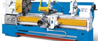
- turning (screw-cutting, CNC or automatic lines);
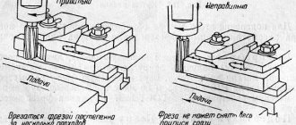
- milling (vertical, horizontal, universal);
- drilling (radial or vertical type);
- gear processing;
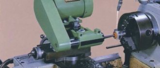
- grinding;
- sharpening
Within each category there is a division based on the principle of versatility and degree of automation.
Depending on the configuration of the cutting tool, such equipment may differ in appearance and functionality.
Modern metal-cutting equipment at the exhibition
You can find out more information about modern models of profile equipment at the Metalworking exhibition
, which will take place on the territory of the Expocentre Fairgrounds.
The supply of metal-cutting equipment is one of the key issues that will be covered during the event.
Due to the international level of the exhibition, leading manufacturers from around the world will take part in it.
Domestic entrepreneurs will have a unique opportunity to communicate directly with representatives of suppliers, discuss plans and prospects for further cooperation, as well as specific issues - rental of metal-cutting equipment, repairs, warranty and post-warranty service, modernization, etc.
Forging and pressing equipmentWelding equipmentModern welding equipment
Feedback subsystem
The main elements of the feedback subsystem are sensors that function as a measuring system. They control the position and speed of the knife. The control unit receives signals and creates new ones, based on calculating the difference between the current and specified parameters.
Help : The main task of the feedback system is to provide the US with information about the current position of the actuator of the device and the speed at which the motors operate.
AL control systems
The design of the automatic line is completed and integrated into one by a control system, which, together with a set of working and idle speed mechanisms, is an essential component of an automatic machine that performs a given technological process without human intervention. The control system determines the nature of the interaction of the controlled working parts of the automatic machine and combines:
- control system for all movements and the order of operation of the main and auxiliary mechanisms;
- blocking and alarm systems that ensure trouble-free operation of the main and auxiliary mechanisms;
- a control system used for adjustment of machines and tools;
- control system used to analyze processing results
AL control systems use electrical, hydraulic and pneumatic communication devices, which are divided into:
- to external ones (ensure coordination of the work of AL sections independent from each other);
- internal (control circuits ensuring the sequential operation of individual mechanisms of the machines included in the AL);
- intermediate (ensure coordinated operation of individual machines of any section of the AL);
- auxiliary (coordinate the operation of individual units with other control systems).
External and auxiliary connections are almost always electrical, and intermediate connections are combined (electromechanical, electrohydraulic or electropneumatic). Internal connections are provided by various devices: mechanical, electrical, pneumatic, hydraulic or a combination thereof. On automatic lines, control of the sequence of operating phases of units, depending on the purpose and composition of the equipment, the size of the line, as well as the duration of its operation cycle, can be centralized, decentralized or mixed.
The automatic line control system includes a program carrier, a reading device, a program input device, a transfer-converting device, an actuator, and a feedback system. The main software carriers from which AL control commands are received are:
- movable stops (for example, in AL, power tables are used, on the upper plane of which spindle units with an independent rotation drive are installed - milling, boring, turret headstocks. The various stages of the table cycle are switched on by a command received from the limit switch after pressing the stop);
- camshafts with cams (for example, when multi-spindle or single-spindle automatic lathes controlled by one or two camshafts are included in the AL - when specialized machines are included in the AL);
- copiers (for example, the same hydrocopying semi-automatic lathes);
- punched tapes, CDs, flash cards.
The control of each individual machine must be consistent with the general control of the AL.
CNC control subsystem
The central part of the CNC system is the control subsystem. It is capable of reading the control program and issuing commands to various machine devices to perform a certain type of work. It also interacts with humans and allows the operator to control the processing.
Open
Open control systems have hardware that is almost the same as that of a home computer. Their advantage lies in the availability and low cost of electronic elements, many of which can be purchased at a simple computer store. But the reliability of such systems is lower than that of closed ones.
Closed
Closed control systems have their own algorithms and work cycle, as well as their own logic. Such systems have one important advantage: they are highly reliable, since all their elements have been tested for compatibility. The disadvantage of the system is that it is impossible to independently update the software system and edit its settings.
Selection principles
When choosing a metal cutting machine, you need to consider some factors:
- Control system.
- Dimensions, installation weight.
- Ability to perform one or more technological operations.
Advantages and disadvantages
Metal-cutting equipment has a number of strengths and weaknesses. Advantages:
- Automation of the work process with CNC.
- High precision metal processing.
- High performance.
- Reliability, durability.
Flaws:
- The need to install a cooling system.
- Difficulties in repair.
- Experience in CNC setup.
It is important to carefully monitor the work process to reduce the risk of injury or part rejection. Metal cutting precision
Metal cutting precision
Manufacturers and cost
Among the manufacturers of metal-cutting machines there are:
- Caliber - Russia.
- Energomash - Russia.
- Jet - Russia.
The price depends on the type, size, performance, availability of additional functions, control system. The cost of standard industrial metal-cutting equipment starts from 500,000 rubles.
What are automatic lines
The purpose of automatic lines (AL), like any other equipment, is to increase productivity and increase profits. In this case, efficiency is achieved through multi-tool and multi-position processing of parts, reducing the share of human labor, i.e. concentration of production, complete automation of auxiliary processes and a sharp reduction in the number of service personnel.
Automatic lines are a number of automatically controlled machines, transport and control mechanisms, operating according to a given technological process and representing a single system designed for mass processing of structurally stable products. AL are used primarily in mass production of various industries, and in mechanical engineering they perform a wide range of products. operations: drilling and boring, thread cutting, milling, grinding, turning, gear cutting, forging, foundry, welding, thermal, painting, galvanic, etc.
For the first time, metal-cutting machines were connected by a transmission device in English in 1923-1924. in the manufacture of cylinder blocks for automobile engines. The line performed 53 operations and processed 15 blocks per hour The line was serviced by 21 operators, but it was controlled using levers and therefore was unreliable in operation In 1928, it built a plant in Milwaukee (USA), where the production of automobile frames was fully automated Frame production began from the receipt of a steel strip, which first passed through a control position, where it was checked and straightened. Then, as it moved along the automatic machine line, the strip was cut, bent, punched and pressed into the various shapes needed for different parts of the chassis. All parts were also automatically assembled and riveted, then the assembled frames were treated with metal brushes and wiped for subsequent painting. The line, staffed by 120 workers, mainly adjusters and repairmen, produced about 10 thousand frames daily. Thus, 16 man-minutes were spent on each frame.
In 1929 (USA) she created an automatic system based on modular machines for processing the cylinder block of a machine. The automatic line, created (Canada) on the basis of modular machines, had a main centralized remote control panel. Moreover, each machine (unit) had its own control panel. Thus, for the first time, a single interlocked automatic system of machines was created.
In the Soviet Union, the machine line was first created in 1939-1940. at the Stalingrad Tractor Plant. It consisted of 5 machines connected by conveyors and was intended for processing roller bushings for tracked tractors. The first automatic production line was built on the basis of modernized manually operated machines.
During the Second World War and in the post-war years, automatic machine lines for aggregate machines became widespread in Soviet machine-building plants. In 1946, ENIMS created an automatic line of machine tools for processing tractor engine blocks.
In the same year, a line was created for processing the engine head of the KhTZ tractor. In 1947, four automatic lines were created for processing engine blocks of ZIL-150 trucks. One of the four lines consisted of 8 machines of type A291, A306 and had 8 working positions, 224 spindles, and 20 electric motors. The automatic line was controlled from a central console equipped with a light alarm. The length of the line was 17.2 m. From that time on, the rapid introduction of automatic lines in the USSR began.
At the end of 1955, at the First State Bearing Plant (GPZ-1), a workshop was created and in 1956, it was put into operation, equipped with two automatic lines for the production of ball and roller bearings. The line fully automated all operations of mechanical and heat treatment of rings, inspection, assembly, anti-corrosion treatment, product packaging and chip removal (Fig. 1). Thanks to the introduction of automatic lines, the production cycle for manufacturing bearings was reduced by 4-5 times, and output per worker increased by 2 times.
Rice. 1. Automatic workshop at GPZ-1
Automation levels
According to the level of automation, metalworking machines are divided into the following types:
- Manual equipment. All mechanisms are controlled by humans.
- Semi-automatic devices. In such machines, half of the mechanisms operate automatically, while the other requires adjustment and control by a master.
- Automatic machines. Equipment that can work independently. The operator should initially set the algorithm for the moving mechanisms.
- CNC machines. Fully automated designs that require a program to operate. In accordance with it, the mechanisms and working parts of the machine will move.
The most popular are machines equipped with CNC systems. Numerical control consists of several key elements:
- Console - through it the operator sets the program according to which the production process will take place. In addition to automatic operation, the console has a remote control for manual control.
- A controller is a mechanism that calculates future movements of moving mechanisms and machine elements. The controller is a powerful microprocessor that controls all mechanisms.
So that the operator can see what program he is specifying, there is a screen in the CNC system. It displays algorithms, dimensions of the workpiece being processed, possible errors and inaccuracies.
Automation of metalworking
Working principle of CNC
The functioning of the CNC machine is carried out in the following sequence:
- To begin with, the part processing program is entered into the device’s control unit.
- It carries out the entire data processing process, prepares all motion commands and sends them to the drive system.
- The drive controls the movement and speed of the product blocks.
- The feedback system remembers data about the location and speed of movement of the axes and sends a signal to the control unit.
- The BUS compares the feedback signals with the initial ones and if there are errors, it corrects them and sends new signals to the execution mechanism to correct the process.
- A control panel with a screen is used to view commands by the operator.
Classification of automatic lines
Considering the widespread use of AL in industry, they are classified according to different properties: according to the type of equipment, the location of the equipment, the type of connection between machines, the method of transporting workpieces, AL is divided into rigid (synchronous) and flexible (asynchronous), through and non-through, branching and non-branching.
Based on the type of equipment, automatic lines are distinguished, composed of universal or specialized machines specially built for a given AL. The last two types must be modernized and automated before being integrated into the line.
Based on the location of the equipment, ALs are divided into:
- into linear, circular, rectangular, zigzag, z-shaped;
- single-threaded and multi-threaded;
- with dependent and independent flows;
- with transverse, longitudinal and angular arrangement of the main technological equipment.
Most layouts have an open structure, providing easier access for maintenance and repair.
According to the type of connections between the machines, ALs are divided into:
- to hard (synchronous). Such inter-operational communication is characterized by the absence of inter-operational backlogs. Workpieces are loaded, processed, unloaded and moved from machine to machine simultaneously or at multiple intervals; if any device stops, the entire line stops;
- non-rigid (asynchronous). Interoperational connections are ensured by the presence of interoperational backlogs located in storage tanks or a transport system. This makes it possible, if any machine fails, to not stop the work of the remaining machines until the interoperational backlog is exhausted.
According to the method of transporting processed parts, there are:
- with through transportation through the working area of machine tools - used mainly when processing body parts on aggregate machines;
- with overhead transportation of workpieces - used for processing gears, flanges, shafts and other parts;
- with lateral (frontal) transportation - used when processing crankshafts and camshafts, liners, large rings;
- with rotary transportation - used on rotary ALs, where processing and transportation are fully or partially combined
AL can be divided according to the method of moving workpieces from position to position:
- to satellite (for processing parts with complex shapes that are difficult or impossible to transport and secure automatically using mechanical devices);
- satellite-free (for processing parts with developed base surfaces, guaranteeing their reliable and accurate installation on the conveyor and in the clamping device).
The design of the machines included in the lines (both specially built for a given AL, and universal or specialized) does not undergo significant changes when integrated into the AL. Only the control system is subject to modification (the operation of each individual machine must be coordinated with the operation of the entire line), and the machine is equipped with a device for automatically loading the workpiece from the conveyor. AL equipment, in addition to machine tools, includes transport systems and control systems.
Methods for programming CNC machines
There are two main methods of CNC programming: online (manual) and using an independent control program. The first method allows the operator to manually, directly using the controls, enter the desired program for processing the part, make the necessary adjustments or debug the operation of the mechanisms. It is characterized by its simplicity and the absence of the need to use computers and special software. However, it is not suitable for the implementation of complex technological processes.
The advantages of operational control of machine tools include:
- step-by-step control over the production of a part;
- ease of programming;
- no need to attract highly qualified programmers.
Programming using a control program is the most popular, as it allows you to speed up the set of many standard processing procedures, debug them and ensure correct operation. This control method is suitable for enterprises that produce complex parts that require several sequential or simultaneous processing cycles in a single technical process.
The main advantages of controlling machines using a control program include:
- significant savings in time required for reprogramming;
- ease of programming of many similar machines;
- the ability to make edits to the program and check the correctness of its execution before launching it on the CNC.
General classification
The classification of metal-cutting machines is carried out according to various factors. These are divisions by weight, dimensions, type, accuracy class, degree of automation, and versatility. We need to talk about each of their groups in more detail.
Classification by type
There are 9 types of installations based on the type of equipment:
- Lathes. They occupy approximately 30% of the total mass of metal-cutting devices. The workpiece is clamped in a special clamp. The cutting process begins after installing the cutters, which remove a layer of metal under the influence of rotation.
- Boring, drilling units. They occupy 20% of the total mass of machines. The parts are fixed on the work table. Cutting occurs due to the rotation of the spindle with a drill clamped in the chuck.
- Grinding, grinding, polishing machines. They occupy 20% of the total mass of metal cutting installations. Metal cutting occurs due to the rotation of the abrasive material, which comes into contact with the working surface. The processing speed depends on the size of the abrasive.
- Devices for physical and chemical cutting of workpieces. Least common equipment.
- Devices for processing threads and teeth. Occupies 6% of the mass. Used for threading, manufacturing, and sharpening gears.
- Slotting, broaching, planing machines. They occupy 4% of the mass of metal-cutting equipment.
- Milling machines. They occupy 15% of the total mass. Processing of metal workpieces occurs due to the rotation of cutters of different shapes.
- Split installations. Used to separate reinforcement, profiles, corners.
- Machines for performing various operations related to cutting.
Classification by versatility
A separate division of metal-cutting machines is based on their versatility. There are two groups:
- Narrow profile installations. Used to perform one specific technological operation.
- Universal units. They are large-sized structures that are designed to perform various technological operations.
Classification by degree of accuracy
In terms of accuracy, metal-cutting machines come in several types, each of which has its own marking:
- Increased - denoted by the letter P.
- Normal - designation N.
- High - indicated by the letter B.
- Particularly high - designation A.
- The highest accuracy is indicated by the letter C.
To use units marked B, A, C, you need to prepare the room in advance. It must maintain a constant temperature and humidity level.
Classification by degree of automation
Based on the degree of automation, the following types of metal-cutting machines are distinguished:
- Manual models. The worker needs to clean, prepare workpieces, set up all moving elements independently, and coordinate the work process.
- Semi-automatic machines. The worker needs to change parts independently, turn on and off moving mechanisms.
- Automatic machines are units that process workpieces independently. Used in mass production.
- CNC equipment. The operator sets the required algorithm through the program. The moving mechanisms work independently, select optimal modes, load and unload parts.
CNC machines are gradually replacing other machines due to high processing accuracy and increased productivity.
Metal cutting automatic machine
Classification by weight
Industrial metal-cutting machines are divided by weight. Highlight:
- Lightweight - structures weigh up to 1000 kg.
- Medium - weight starts from 1 ton and ends at 10 tons.
- Large - weight from 16 to 30 tons.
- Heavy - weight from 30 to 100 tons.
- Super heavy - structures weigh more than 100 tons.
Designations are indicated in the technical data sheet.
A little history
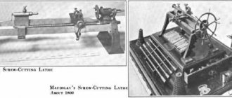
However, the modern stage in the history of CNC machines began only a century and a half after the invention of Jacquard, in the United States of America. After the end of World War II, in the late 40s, John Parsons, the son of the owner of Parsons Incorporated, tried to control the machine using a special program that was entered from punched cards. Parsons did not achieve any positive results, so he turned to specialists at the Massachusetts Institute of Technology for help.
The employees of the institute's laboratory of servomechanics did not improve the design presented to their attention, and they quickly forgot about Parsons. But about his ideas - no. Having created their own design, they initiated the institute’s purchase of a company that produced milling machines. After which the leadership of the Massachusetts Institute of Technology entered into a contract with the US Air Force. The contract dealt with the creation of a new type of high-performance machines for processing propellers by milling.
The operation of the milling machine, which was assembled by the laboratory staff in 1952, was controlled according to a program read from a punched tape. This design turned out to be too complex, and the desired result was not achieved. However, the story became public, information about the new development was published and aroused great interest from competitors. Several well-known companies simultaneously began their developments in this direction.
The greatest success was achieved by the designers of Bendix Corporation. The NC device released by Bendix has been in production since 1955 and has already been actually used to control the operation of milling machines. The new product took root with difficulty, but thanks to the interest and financial assistance of the military department, over two years more than 120 CNC machines were produced, which significantly increased labor productivity and the accuracy of machine work.
Even then, the undeniable advantages of the NC numerical control system for machine tools were noted: a significant increase in labor productivity and significantly higher precision of surface processing. But truly revolutionary changes in the field of CNC machines took place when specially designed microprocessors and microcontrollers were used as a “smart” module that controls the operation of the machines. The technical term “CNC”, which began to designate these systems abroad, is an abbreviation of the English words ComputerNumericalControl.
Lectures on MRS.doc
7
Machine modules and flexible systems
Parallel circular
^ Flexible production systems Flexible production system ^ Flexible automated automation line
- ^ Shaping devices are the working parts of the machine associated with the shaping of products and positioning processes, i.e. move the workpiece (or tool) along programmed coordinates during processing or before processing. A distinctive property of this group is that the trajectory and path of movement can be changed depending on the entered program.
- ^ Manipulating devices - designed to execute constant commands associated with the automatic cycle of equipment operation. They change cutting modes, directions and speeds of movement of machine mechanisms, control cooling, change cutting tools or workpieces, secure them, transport and store them. The moment of commissioning and the sequence of their operation may vary. This is determined by the cyclic automation program.
- ^ Auxiliary devices - serve the processing process, for example, provide automatic waste collection, lubrication of the machine, suction of fog and dust, operation of the hydraulic and pneumatic systems, etc. They usually have an autonomous control system. The most important and complex in their management are the first and partly the second group of devices.
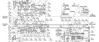
Positioning automatic cycle Algorithm^ Automatic control system Program carrier control program^ Classification of automatic control systems and their comparative analysis self-adapting self-adjusting self-organizing self-learning Continuous Discrete^ Control systems with RF, their operating principle and classification^ Control systems of group 1 with RF^ Control systems of group 2 with RF^ Control systems of group 3 with RF^ Features calculation and design of a control system with PB^ Cyclic program control systems^ Machine tools with a CPU^ Tracking automatic control systems^ Tracking copying control systems Mechanical copying systems.^ Electric tracking copying systems^ Electrocopy milling semi-automatic mod. 6441B^ Electrocontact copying systems.^ Graphic tracking copying systemsmodel 1722^ Electro-hydraulic copying systems^ Photocopying systems Numerical control systems
Basic principles of numerical program controlFirst Second^ Classification of CNC systems Based on the technological tasks of processing control^ Positional CNC systems^ Contour CNC systems milling machines^ Combined CNC systems^ II. Based on the presence of feedback Closed Open ^ III. Classification depending on the level of electronic technology NC class SNC class CNC class HNC class DNC class ^ Typical block diagram of the CNC system ^ Information input and reading block ^ Memory block ^ Interpolation block ^ Feed drive control block ^ Feed speed block ^ Control and display panel ^ Block program correction^ Block of canned cycles^ Block of technological commands^ Power supply^ Feedback sensors (DOS)^ General principles of program coding^ Unitary code.^ Decimal number system^ Binary number system Binary decimal number system.^ International ISO code – 7bit 7
Site search:
NUMERICAL MACHINE CONTROL SYSTEMS
NUMERICAL MACHINE CONTROL SYSTEMS
Structure of CNC systems
In general, the structure of the “CNC Machine” complex can be represented as three blocks, each of which performs its own task: a control program (CP), a CNC device (CNC) and the machine itself (Fig. 1.1).
Rice. 1.1. Functional diagram of CNC machine control
^ COMPLEX “CNC MACHINE”
All blocks of the complex work interconnected in a single structure. Control program
contains an enlarged coded description of all stages of the geometric and technological formation of the product. This description should not be ambiguous. In the CNC device, control information in accordance with the NC is translated and then used in the computational cycle. The result is the formation of operational commands in real machine time.
Machine
is the main consumer of control information, the executive part, the control object, and in terms of design - the supporting structure on which automatically controlled mechanisms are mounted, adapted to receive operational commands from the CNC. Such mechanisms include, first of all, those that are directly involved in the geometric shaping of the product. Depending on the number of motion coordinates specified by the feed mechanisms, a processing coordinate system is formed. The coordinate system can be flat, spatial three-dimensional, spatial multidimensional. The functionality of a real CNC system (CNC) is determined by the degree of implementation of a number of functions when controlling equipment. Let's look at a brief description of these functions.
^ Input and storage of system software (SPO). Open source software includes a set of programs that reflect the algorithms for the functioning of a specific object. In CNC control systems of lower classes, the software is built into the structure and cannot be changed, and the CNC control system can only control this object (for example, only machines of a turning group with two coordinates). In multi-purpose systems that provide control of a wide class of objects, when setting up the control system to solve a certain range of problems, the software is introduced from the outside. This is necessary because different objects have differences in shaping algorithms in the number of control coordinates, speeds and accelerations of tool movement. The variety of drive types and the composition of technological commands of objects leads to differences in the number and nature of exchange signals.
In autonomous multi-purpose control devices, the software is entered from a punched tape, from a floppy disk, from a compact disc (CD), and in automated devices (as part of an automated process control system, state control system) - through a communication channel with a top-level computer. Naturally, the SPO is stored in the system memory until the control object changes. When replacing a control object (for example, instead of a lathe, an industrial robot is connected to the CNC), it is necessary to enter new programs (SPO) into the CNC, which would determine the algorithms for the functioning of this new object.
It is necessary to distinguish between software and control programs: the software remains unchanged for a given control object, and the control programs change when different parts are manufactured at the same object. In multi-purpose control systems, the memory for storing SOPs must be non-volatile, i.e. save information in the event of a power outage.
^ Entering and storing UE. The control program can be entered into the control system from the control panel, from a floppy disk, or via communication channels with a higher-level computer. The memory for storing the UE, which is usually represented in the ISO code, must be non-volatile. In higher-class control systems, the program program is usually entered immediately and in its entirety and is stored in the system’s RAM. Powerful computer CNCs allow you to record and store a large number of CPs in the memory of your computer.
^ Frame interpretation. The control program consists of components - frames. Working out the next frame requires a number of preliminary procedures called frame interpretation. For continuity of loop control interpretation procedures i
1st frame must be implemented during object control on
the i
-th frame. In other words, the control system must be ready to immediately (without interruptions for reading and recognizing frames) issue control commands in accordance with the commands of the next frame after the execution of the commands embedded in the current frame.
Interpolation. The control system must ensure, with the required accuracy, the automatic receipt (calculation) of the coordinates of intermediate points of the trajectory of the elements of the controlled object according to the coordinates of the extreme points and the specified interpolation function.
^ Control of feed drives. The complexity of control depends on the type of drive. In the general case, the task comes down to organizing digital positional tracking systems for each coordinate. The input of such a system receives codes (code) corresponding to the interpolation results. These codes must correspond to the coordinate position (linear or angular) of the moving object. Determination of the actual position of a moving object and reporting it to the control system is carried out by feedback sensors. In addition to control in the motion mode along a given path, the organization of some auxiliary modes is also necessary: coordination of the drive control system with the true position of feedback sensors, setting the drive system to a fixed zero of the machine, control of deviations from permissible coordinate values, automatic entry of drives into braking mode according to certain laws and etc.
^ Main motion drive control. The control involves turning the drive on and off, stabilizing the speed, and in some cases, controlling the angle of rotation as an additional coordinate.
^Logical control. This is the control of discrete-action technological units, the input signals of which produce operations such as “enable”, “disable”, and the output signals record the states “on”, “disabled”. Recently, CNC controls of the highest level have appeared, possessing the properties of non-standard logic, a kind of high intellectual level.
^ Correction for tool dimensions. Correction of the NC for the length of the tool is reduced to a parallel transfer of coordinates, i.e. displacement. Taking into account the actual radius of the tool is reduced to the formation of a trajectory that is equidistant to the programmed one. In a number of high-level CNC controls, it is possible to correct and take into account up to 15 different tool parameters in the NC.
^ Implementation of loops. Isolating repeating (standard) sections of a program, called loops, is an effective method for reducing programmatic complexity. So-called fixed cycles are characteristic of certain technological operations (drilling, countersinking, boring, threading, etc.) and are found in the manufacture of many products. When developing a NC program, fixed cycles are indicated in the program, and they are processed in accordance with a specific subroutine stored in the CNC memory by a software system or design diagram. In a high-level CNC, up to 500 standard cycles and subroutines can be stored in the memory of the control computer and, therefore, can be quickly used.
Programmed technological cycles correspond to repeating sections of a given workpiece. These cycles in certain CNC control systems can also be selected and stored in the RAM of the CNC, and when repeated in accordance with NC commands, they can be implemented by calling them from RAM.
^ Tool change. This function is typical for multi-tool and multi-task machines. The task of changing a tool generally has two phases: searching for a magazine slot with the required tool and replacing the used tool with a new one. The GAP with a tool warehouse has complex systems for automatically supplying (replacing) tools to machine tool stores.
^ Correction of errors of mechanical and measuring devices. Any specific machining unit (i.e., control object) can be certified using measuring instruments of a sufficiently high accuracy class. The results of such certification in the form of error tables (intra-step error, accumulated error, backlash, temperature errors) are entered into the CNC memory. When the system is operating, the current readings of the unit sensors are corrected by data from the error tables. High-level systems have built-in control and measuring systems that monitor the main parameters of the machine in the so-called background mode. The control results are immediately used to make the necessary corrections.
^ Adaptive Processing Control. To carry out such control, the necessary information is obtained from specially installed sensors, with the help of which the moment of cutting resistance or components of cutting forces, power of the main movement drive, vibration, temperature, tool wear, etc. are measured. Most often, adaptation is carried out by changing the contour speed or the speed of the main movement drive .
^ Accumulation of statistical information. Statistical information includes recording the current time and operating time of the system and its individual components, determining the equipment load factor, accounting for manufactured products, recording its individual parameters, etc.
^ Automatic built-in control. The organization of such control in the processing area is especially relevant for the GAP. Continuous monitoring of the formed dimensions of the processed product is one of the main tasks of improving processing quality.
^ Additional features. Additional functions include the following: exchange of information with a top-level computer, coordinated control of technological module equipment, control of elements of an automatic transport and warehouse system, control of external devices, communication with the operator, technical diagnostics of technological equipment and the CNC system itself, optimization of individual modes and cycles technological process, etc.
^ INFORMATION STRUCTURE OF CNC MACHINES
The CNC includes the means involved in the development of control actions on the executive bodies of the machine and other mechanisms according to a given program, the means for introducing and controlling the influence of external and adaptive corrections, as well as the means of diagnosing and monitoring the performance of the CNC and the machine during the manufacture of the part. The machine control system must include: technical means; software (for programmable control systems); operational documentation.
The technical means of the control system include: the computational and logical part (including storage devices of various types for programmable systems); means of forming influences on the executive bodies of the machine (drives of feeds and main movement, executive devices of electrical automation, etc.); means of communication with sources of information about the state of the controlled object (measuring transducers of various types, control, adaptation, diagnostic devices, etc.); means that ensure interaction with external systems and peripheral devices (communication channels with a higher-ranking computer, etc.). Technical means,
included in the control system, are usually structurally designed in the form of
an autonomous device
- CNC.
The main classification features of a control system are the level of complexity of the controlled equipment and the number of axes connected by solving a single interpolation problem in time. Based on this feature, CNC machine tools are divided into the following groups:
- CNC with rectangular shaping along one coordinate axis;
- Control system with contour shaping with a limited range of functions along two or three coordinate axes (information channels);
- CNC control with expanded functionality for equipping multi-purpose machines and machines with complex volumetric shaping along four to five coordinate axes (information channels);
- Control control with expanded functionality, including special control tasks, for equipping heavy and unique machines and machine modules along 10-12 coordinate axes (information channels).
The complexity of the control system structure is determined by information characteristics and is assessed by the number and nature of information channels used during system operation. Due to the fact that the information purpose of the devices and their elements included in the control system is different, they are classified into different hierarchical ranks. Typically, the control system of machine tools has a two- or three-rank structure, while providing access to higher ranks for work as components of state control systems, automated lines, sections and other production complexes.
In the structural and information analysis of control systems, a certain distribution of levels and information channels is adopted.
Level 0 rank is a combination of factors such as temperature, quality of materials, data from control and measuring equipment, etc.
The 1st rank level is the converters that generate channel information:
- according to the position of the machine’s executive bodies,
— according to technological and dimensional parameters characterizing the state of the technological system;
- according to the parameters of disturbances introduced into the technological system;
- by the accuracy of the part processed on the machine;
- to replace fixtures, tools and machine readiness;
- to monitor the correct progress of the cutting process and record any problems that arise, as well as develop ways to eliminate them.
Level 2 of the rank is a set of executive adjustable drives and actuators of the machine:
the main ones that carry out the programmatic movement of the executive bodies,
auxiliary, performing various kinds of technological commands, including with the help of a robot
additional, intended for adjustment and corrective movements.
Level 3 rank - level of technical means of control systems.
Levels of the 4th and higher ranks go beyond the control system and the machine. The 4th rank level includes, for example, an external computer.
In the most general case, control systems for metal-cutting machines have a three-rank structure.
Classification of CNC devices
All threads of control of the automatic mechanisms of the machine converge to the CNC. Structurally, the CNC is designed as an autonomous electronic unit, having a CP input device, a computing part, and an electrical communication channel with the automatic mechanisms of the machine.
The appearance of the CNC is largely determined by the control panel, from which one can select one of the following machine control modes: manual, adjustment, semi-automatic, automatic; The program is corrected during its debugging, a correction is introduced, the execution of commands is monitored and the correct operation of the machine and the CNC device itself is monitored, etc. The control panel (remote) of the CNC, in turn, is determined by the programming system adopted for this device, characteristic signs of the adopted program control system, CNC class.
In accordance with the international classification, all CNC controls according to the level of technical capabilities are divided into the following main classes: NC (Numerical Control); SNC(Stored Numerical Control); CNC (Computer Numerical Control); DNC (Direct Numerical Control); HNC (Handled Numerical Control); VNC (Voice Numerical Control).
The structural and information analysis of these systems is quite complex, although it allows us to highlight the presence of certain functional elements and information channels in them. The classification for real CNC controls is also conditional, since the implementation of CNC functions may be such that the real version of the control system is a synthesis of individual features of systems of different classes. This especially applies to CNC machines with DNC
, which are implemented as systems of classes
DNC-NC, DNC-SNC, DNC-CNC
, etc. to CNC class
CNC
, which are implemented as systems
VNC, CNC-HNC
, etc.
NC CLASS SYSTEMS
And
SNC
Machines equipped with CNC of NC
and
SNC
, are currently still in practice at enterprises, but the production of systems of these classes has already been discontinued.
These are the simplest control systems with a limited number of information channels. These systems do not contain an operational computer, and the entire flow of information is usually limited to the 3rd rank level. An external feature of the NC
and
SNC
is the method of reading and processing the NC.
NC class systems
.
In NC
Frame-by-frame reading of punched paper tape is adopted throughout the processing cycle of each workpiece.
NC
class systems operate in the following mode. After turning on the machine and the CNC, the first and second frames of the program are read. As soon as their reading ends, the machine begins to execute the commands of the first frame. At this time, the information of the second program block is in the CNC memory. After completing the first frame, the machine begins to process the second frame, which for this purpose is output from the memory device. While the machine is processing the second frame, the system reads the third frame of the program, which is entered into the memory device that has been freed from the information of the second frame, etc.
The main disadvantage of the considered operating mode is that in order to process each subsequent workpiece from a batch, the CNC system has to read all the frames of the punched tape again; during such reading, failures often occur due to the insufficiently reliable operation of the CNC reading devices. As a result, some parts from the batch may be defective. In addition, with this mode of operation, the punched paper tape quickly wears out and becomes dirty, which further increases the likelihood of reading failures. Finally, if the frame contains actions that the machine performs very quickly, then the CNC may not have time to read the next frame during this time, which also leads to failures.
Currently CNC class ^NC
are no longer produced.
SNC
class systems .
These systems retain all the properties of NC
, but differ from them in increased memory capacity.
SNC-
class systems allow you to read all program frames and place the information in a large-capacity storage device.
The punched paper tape is read only once before processing the entire batch of identical parts and therefore wears out little. All workpieces are processed using signals from a memory device, which dramatically reduces the likelihood of failures and, consequently, defective parts. Currently, SNC
are no longer produced.
However, the operating diagram of these systems is very indicative and determines the essence of program control. When operating a machine controlled by an NC or SNC
, the coded program is entered on punched tape.
In addition, individual commands can be entered from the CNC control panel or from the machine control panel. Information from the punched tape enters memory through input and decoding blocks. When the machine operates in automatic mode, program commands processed by the interpolator are sent to the drives through control units. The speed of the drives is regulated according to the data of the feedback system, and the movements for the feed drives are regulated according to the data of the PD travel sensors. CLASS SYSTEMS CNC, DNC, HNC
The development of computer technology, the reduction in the dimensions of its elements, and the expansion of functionality made it possible to create a computer-based CNC, installing a powerful computer equipment directly to the machine in the production workshop. The new systems combined machine control functions and solving almost all NC preparation tasks.
CNC class systems
The basis of CNC class CNC
are:
- a computer programmed to perform numerical control functions,
- communication units with coordinate drives, units for issuing technological commands in the required logical sequence,
- system controls and indications,
- channels for data exchange with the upper-level central computer.
In CNC
It is possible during the operation period to change and adjust both the part processing program and the operating programs of the system itself in order to take into account the features of this machine as much as possible. Each of the functions performed is provided by its own set of subroutines. Subroutines are linked by a common coordinating dispatcher program, which provides flexible interaction between all blocks of the system.
The control system software package can be built on a modular basis. The main modules of such a system are:
- CP loading control program, including frame input and decoding subroutines;
- machine control program, including a subroutine for controlling coordinate movements and a subroutine for executing technological commands.
The coordinate movement control program consists of blocks for interpolation, speed setting, and rapid traverse control, and these blocks, in turn, include the following modules:
- data preparation program;
- organizing dispatcher program;
- drivers are standard operators for working with external devices.
CNC system memory
The program can be entered in full not only from a floppy disk or via an external communication channel, but also in separate frames - manually from the CNC control panel. In program frames, not only commands for specifying individual movements of working bodies can be written, but also commands that specify entire groups of movements, called canned cycles, which are stored in the SPU memory device. A number of systems have a library of standard programs, built-in SAP, etc. This leads to a sharp decrease in the number of MT personnel, to a reduction in the time required for its preparation and to an increase in the reliability of the machine.
^CNC class systems
allow you to quite simply perform dialogue-based refinement and debugging of CPs and their editing, using manual input of information and displaying it on the display, as well as obtaining an edited and completed program on a magnetic disk (floppy disk), etc. During the work process, various types of corrections are allowed.
CNC class systems
:
low cost,
small dimensions,
high reliability,
many CNCs of this class have mathematical software that can be used to take into account and automatically correct the constant errors of the machine and thereby influence the totality of reasons that determine the accuracy of processing,
the use of control and diagnostic systems increases the reliability and performance of machines with CNC class ^ CNC
.
Some CNC class CNCs
have special test programs to check the performance of all structural parts of the system. These test programs are executed every time the device is turned on, and if all parts are working properly, a signal is generated that the system is ready for operation. During the operation of the machine and CNC, test programs are processed in parts in the so-called background mode, without interfering with the development of the main NC. If a malfunction occurs, a code appears on the light indication board, then using the code, the location and cause of the malfunction are determined from the table. In addition, the system detects errors associated with improper operation of the device or exceeding thermal parameters, allows you to find the power supply voltage and other parameters.
An integral part of CNC class CNC
is an extensive built-in memory that can be used as a CP archive.
A very important means of optimizing the connection between the processor CNC and the machine is the introduction of machine parameters or constants into memory. Using these constants, restrictions on the processing area can be automatically taken into account, requirements for the dynamics of specific drives can be specified, phase trajectories of acceleration and deceleration can be formed, specific features of speed boxes and feed drives can be taken into account, systematic errors in these gears can be compensated, etc.
A real representation of a high-level CNC class CNC involves the presence of two consoles - an operator panel and a machine console, the combination of CNC units with a programmable controller, a separate type of control system for feed and spindle drives. The system is distinguished by simple programming and user comfort, provides all types of functions of a modern CNC, enhanced correction systems for compensation of backlash, measuring system errors, screw stroke errors, NC errors, has a set of standard cycles for programming, a universal interface, etc.
DNC class systems
DNC class systems
can be controlled directly by drives from a central computer, bypassing the machine's reading device.
However, the presence of a computer does not mean that the need for CNC control on machine tools completely disappears. In one of the most common variants of DNC
, each type of equipment on the site retains its CNC classes
NC, SNC, CNC
. The normal mode for such a section is a computer-controlled operating mode, but in conditions of temporary computer failure, such a section remains operational, since each type of equipment can operate using a floppy disk prepared in advance in case of an emergency.
In DNC
includes the management of other equipment of the automated site, for example, an automated warehouse, transport system and industrial robots, as well as the solution of some organizational and economic problems of planning and dispatching the work of the site.
the DNC
software and mathematics can be a specialized system for automating the preparation of CP.
Editing the CP in DNC
is possible on an external computer on which automated preparation of the CP is carried out, on a computer that controls a group of machines, and on a computer built into the CNC of a specific machine. In all cases, prepared and edited CPs for the equipment of the site are stored in the computer memory by the control group of machines, from where they are transmitted to the machines via communication channels.
HNC class systems
Operational CNC machines of HNC
allow manual entry of programs into the electronic memory of the CNC computer directly from its console.
A program consisting of a sufficiently large number of frames is easily typed and corrected using keys or switches on the CNC control panel. After debugging, it is fixed until the end of processing of a batch of identical workpieces. HNC
class CNCs , having a simplified design, in some cases did not have the ability to make corrections, buffer memory and other elements.
Modern CNC class ^ HNC
built on the basis of the best CNC class
CNC machines
, only formally differing from the latter in the absence of devices for inputting NC from punched tapes.
HNC
class CNCs have an input device for connecting external devices.
The latest CNC models of the HNC
have an increased memory capacity of the built-in microcomputer. Such devices allow programming from the CNC console in dialogue mode and using a large archive of standard subroutines stored in the memory of the built-in microcomputer. These subroutines, upon command from the remote control, are called up on the display screen; both the processing diagram and the text with a list of necessary data for entering into the CNC for the selected subroutine are displayed on the screen.
the CNC, DNC, HNC classes also provide automatic selection of tools from those available in the machine shop, determine the processing modes of the selected tool for parts made of various materials, find the optimal sequence of operations, etc. In general, such systems allow you to prepare the NC directly at the machine according to the drawing of the part without any special preliminary work of a technological nature. This, naturally, imposes increased demands on the professional preparedness of the CNC machine operator. A number of CNC controls of the class under consideration allow programming in parallel with the operation of the machine using a previously worked out and stored in the CNC memory program, which eliminates machine downtime.
CNC classes CNC, DNC, HNC
refer to devices with variable structure. The basic algorithms for the operation of these devices are set programmatically and can be changed for various conditions, which makes it possible to reduce the number of modifications of the CNC and speed up their development, including CNCs with self-adjusting algorithms. CNC controls of these classes have the structure of a computer and have the characteristic features of a computer. To operate, the CNC must be programmed accordingly. For this purpose, such systems have special software and mathematics, which is a set of algorithms for processing information received in the form of CP. The software can be entered into the system through an input device, just like the main CP. Then the CNC system belongs to the class of freely programmable. In other cases, the software is stored in the permanent memory of the system at the stage of its manufacture. However, in all cases there are possibilities for changing, supplementing, and enriching this mathematical software, therefore such CNC systems have great flexibility and the ability to functionally expand.
Capabilities of modern CNC classes CNC, DNC, HNC
are limitless and determined only by the capabilities of the computers used in them.
VNC class systems
VNC class CNCs allow you to enter information directly by voice. The received information is converted into UE and then displayed on the display in the form of graphics and text, which ensures visual control of the entered data, their correction and processing. Speech input of information is being especially actively introduced into robotics; Robot control systems use two methods for converting speech signals into commands: “synthesis by rules” or “synthesis by patterns.”
In the first case, speech input is implemented only if there are rules stored in the memory of the operator console. It is difficult to obtain high quality here due to limited memory capacity and the complexity of voice reporting programs. The system contains a storage device for storing message text codes, a text converter and a synthesizer. The text converter translates the audio signals of the text into phonetic symbols and performs parsing. The resulting symbols are used as code signs to organize the control program.
With the “sample synthesis” method, the synthesizer is based on a linear model of speech production based on main current generators, a linear filter and a learning model. This expands the scope of speech input commands.
VNC class CNC
have not yet become widespread in industry, but are likely to be widely presented in the near future as the most advanced designs providing the highest level of service capabilities.
^ NEURO-FUZZY (NEYPO-FAZZY) CONTROL SYSTEMS
The beginning of work with computer neural networks dates back to the 40s, but only modern computer technologies opened the way to their commercial use. Currently, many companies are working on the creation of neural networks for various purposes, but so far only a few have managed to implement NEURO-FUZZY
management systems into production practice. According to the general belief, the future belongs to these systems.
Computer neural networks are a special type of computer that, to one degree or another, imitate the mental processes of the brain. In these computers, data is organized like brain neurons in a network of multi-level connections. These systems quite simply solve not only ordinary standard problems, but mainly non-standard, non-standard problems that unexpectedly arise during the processing process, the solution of which requires non-standard logic, i.e. certain intelligence. Neural networks solve problems that are completely beyond the capabilities of an ordinary high-speed computer.
^ Neuro-fuzzy CNC Generators W
(
SODICK Co.Ltd
., Japan) is the world's first industrial control system with artificial intelligence based on a computer neural network. The system is used to control electroerosive coordinate piercing machines. Neuro-fuzzy, in addition to a computer neural network, also includes a fuzzy control or fuzzy set control system using expert fuzzy logic.
The system provides fully automated control of electrical discharge machining, ensuring its optimal conditions and modes. Processing programming is carried out in the operator-CNC dialogue, in which the operator only answers graphically illustrated and intuitive questions from the machine (Fig. 1.2).
To set the initial data, no tables of modes and instructions are required; the operator enters a minimum of data, and the system itself automatically calculates the modes and operating conditions of the machine. At the same time, from positioning to the end of processing, CNC codes are not needed, as well as special experience in operating this equipment.
Rice. 1.2. Block diagram of the Neuro-Fuzzy CNC generator W Fuzzy control of processing modes and progress with instant response to any deviations optimizes the process to maximum productivity and efficiency. The neurolearning system automatically corrects the results and achieves the required quality and performance. The self-learning experience is applied by the system in subsequent processing as the system remembers what it does. The system does not require a long time to master; on machines with such systems, even an inexperienced operator works faster and more efficiently than a qualified operator on a machine with conventional CNC systems.
MANAGEMENT TASKS
Programmable controllers
The controller is a specialized device, retrofitted with a terminal in the form of a personal computer. An increase in the power and service level of a personal computer makes it possible to combine the terminal, programmer and controller itself within a single computer system with an additional input-output module for electrical automation signals.
There is a prototype called the ^ PCC system (Personal Computer Controller
– personal programmable controller).
The development of the RCC
is proceeding in the following directions:
- using a single-computer version with a Windows system;
- increasing the number of operator interface functions due to multi-mode control and the use of built-in instrumental programming systems;
- maintaining real-time dynamic graphical models of the managed object;
- the use of visual programming of electrical automation (for example, like the graphic language HighGraph
from
Siemens
).
The main task of the controller is to simultaneously execute several commands and parallel processing of external signals. Each controller process that requires a separate thread runs within the main process. The CPU time allocated by the operating system to the main processor must be divided among threads. Processor time is allocated to threads in separate quanta. Only one thread can be realized in each quantum. All threads are divided into groups according to priorities - the shorter the reaction time to external influences, the higher the priority of the thread
Machine markings
Short designations consisting of letters and numbers indicate different technical characteristics, purpose, and manufacturer of the units. Markings are divided into two groups:
- Marking of serial production machines. The first digit indicates the group, the second the type. The letter after the first two digits indicates a modernization of the design. Next, the operational parameter is indicated by two numbers. After it, the CNC type is indicated in one letter with a number. The last letter with a number designates the CNC computing device.
- Marking of specialized installations. The first two letters indicate the abbreviated name of the manufacturer. After it, the main operational parameter is indicated in three digits. The modification is further indicated by a letter. The last letter and number indicate the CNC computing device.
After such markings, separate symbols may be added that indicate technical characteristics. A more accurate decoding can be found in the tables available on the Internet.