Test tool
TO
category:
Turning
Test tool
Next: Process Processes
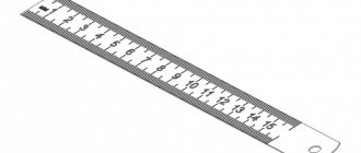
According to the method of application, measuring instruments are divided into three groups: measures, measuring instruments and instruments, calibers. Measures are measuring instruments that reproduce a physical quantity of a given size. These include (Fig. 131) scale steel rulers, tape measures, protractors, plane-parallel gauge blocks, protractors, angle gauges, simple and T-squares.
Rice. 127. Finishing and non-control of the cutter
Methods of measuring with rulers, squares, and templates are shown in Fig. 132 and 133. Measuring instruments and instruments are devices that are used to measure the actual dimensions of a part. The caliper is designed to measure the diameters and lengths of parts with an accuracy of 0.1 mm. It consists of a rod, measuring jaws, a frame, a frame clamp, a vernier 5 and a depth gauge 6. Vernier calipers are produced with measurement limits of 0–200 mm, 0–320 mm and 0–500 mm, 240–700 mm, 320–1000 mm, 500 -1400 mm and 800-2000 mm.
Rice. 128. Devices for sharpening isenner reamers
Rice. 129. A device on a universal sharpening machine for sharpening the front (a) and back (b) surfaces of the cutting part of the blades
Micrometer instruments include smooth micrometers designed to measure the diameter of a part. The micrometer (Fig. 135, a) consists of a bracket, a heel, a screw, a stopper, a stem, a drum, on the conical part of which a vernier scale with 50 divisions is applied, and a ratchet that serves to limit the feed of the micrometer screw. They are made at intervals of 25 mm; 0—25, 25—50, 275—300 mm, then at intervals of 100 mm: 300—400; 400-500; 500-600 mm. Measurement accuracy 0.01 mm. A micrometric bore gauge is designed to measure the internal dimensions of a part and consists of a measuring surface, a stem, a stopper, a micrometer screw, a drum and a nut. Measurement accuracy 0.01 mm.
A micrometer depth gauge is used to measure the depth of holes, the height of ledges, etc. It consists of a base, a micrometer head, a locking device, a cylindrical socket and replaceable measuring rods.
Rice. 130. Sharpening the rear surfaces of the cutting part of the die feathers (a) and the front surface of the die (b)
Rice. 131. Test tool
Rice. 132. Measurement of linear dimensions (a), diameters of bodies of rotation (b) and wall thickness of a hollow body (c)
Rice. 133. Templates: a...c—profile; g…e—threaded; g—radial; h—lamellar
A dial indicator (Fig. 136, b) is used to measure the thickness and deviation of a part from symmetry. It consists of a body, a set screw, a dial, a rim, a pointer, a small vernier hand, a case, a rod, a neck, a ball and a head. Measurement accuracy 0.01 and 0.001 mm.
Calibers are scaleless control instruments. These include limit plug gauges (Fig. 137, a, b), consisting of body 2 and two plugs: a pass-through and a non-pass-through. These plugs are used to measure the internal diameter of the hole. Measurement limit from 1 to 50 mm. To check large holes, one-sided (Fig. 137, c), mounted (Fig. 137, d) and incomplete (Fig. 137.5) plugs are used. Clip gauges are used to measure the diameter of shafts. Rigid staples (Fig. 138, a-g) measure diameters. Measurement range from 1 to 200 mm. Adjustable clamps are used to control shafts with a diameter of up to 300 mm. A fixed jaw is screwed to the body. The inserts are adjusted from 3 to 8 mm in both pass-through and non-pass-through sizes using screws. After setting the required size, the inserts are locked with bushings with a flat and screws. In Fig. 139 shows methods for measuring diameter. Checking the outer diameter of the shaft with a bracket is shown in Fig. 139, a. The shaft is turned correctly, since the non-passing part of the bracket does not pass through it. The method for checking the shaft hole is shown in Fig. 139, b. The smaller go-through end of the double-sided limit plug fits into the hole, and the larger non-go-through end (Fig. 139, c) does not fit into this hole. Therefore, the hole is bored correctly. Control of the length of the treated part of the surface is carried out with one-sided and two-sided (Fig. 139, d) templates.
Rice. 134. Vernier caliper
Rice. 136. Micrometric depth gauge (a) and dial indicator (b)
Methods for measuring the dimensions of the ring are shown in Fig. 140. For the ring (Fig. 140, a), it is necessary to measure the outer diameters A\ and A2, the inner diameters B1 and B2, and also determine the height of the ring ai, the thickness of the shoulder a2 and the boring depth b. In Fig. 140, b shows the measurement of dimensions a\ and a2 with a small micrometer; in Fig. 140, c - measuring the diameter of A2 with a large micrometer. In Fig. 140, d shows a method for measuring depth b with a depth gauge, and in Fig. 140,(3 - measurement of the internal diameter B2 with a micrometer bore gauge.
Fig. 135. Smooth (a) and threaded (b) minometer, micrometer-bore gauge (c) and extension rod (d) for measuring large diameters
Rice. 137. Calibers for non-control of holes
Inspection and Measuring Tools - Turning
Testing and measuring instruments
Category:
Turning
Test tool
According to the method of application, measuring instruments are divided into three groups: measures, measuring instruments and instruments, calibers. Measures are measuring instruments that reproduce a physical quantity of a given size. These include (Fig. 131) scale steel rulers, tape measures, protractors, plane-parallel gauge blocks, protractors, angle gauges, simple and T-squares.
Rice. 127. Finishing and non-control of the cutter
Methods of measuring with rulers, squares, and templates are shown in Fig. 132 and 133. Measuring instruments and instruments are devices that are used to measure the actual dimensions of a part. The caliper is designed to measure the diameters and lengths of parts with an accuracy of 0.1 mm. It consists of a rod, measuring jaws, a frame, a frame clamp, a vernier 5 and a depth gauge 6. Vernier calipers are produced with measurement limits of 0–200 mm, 0–320 mm and 0–500 mm, 240–700 mm, 320–1000 mm, 500 -1400 mm and 800-2000 mm.
Rice. 128. Devices for sharpening isenner reamers
Rice. 129. A device on a universal sharpening machine for sharpening the front (a) and back (b) surfaces of the cutting part of the blades
Micrometer instruments include smooth micrometers designed to measure the diameter of a part. The micrometer (Fig. 135, a) consists of a bracket, a heel, a screw, a stopper, a stem, a drum, on the conical part of which a vernier scale with 50 divisions is applied, and a ratchet that serves to limit the feed of the micrometer screw. They are made at intervals of 25 mm; 0—25, 25—50, 275—300 mm, then at intervals of 100 mm: 300—400; 400-500; 500-600 mm. Measurement accuracy 0.01 mm. A micrometric bore gauge is designed to measure the internal dimensions of a part and consists of a measuring surface, a stem, a stopper, a micrometer screw, a drum and a nut. Measurement accuracy 0.01 mm.
A micrometer depth gauge is used to measure the depth of holes, the height of ledges, etc. It consists of a base, a micrometer head, a locking device, a cylindrical socket and replaceable measuring rods.
Rice. 130. Sharpening the rear surfaces of the cutting part of the die feathers (a) and the front surface of the die (b)
Rice. 131. Test tool
Rice. 132. Measurement of linear dimensions (a), diameters of bodies of rotation (b) and wall thickness of a hollow body (c)
Rice. 133. Templates: a...c—profile; g…e—threaded; g—radial; h—lamellar
A dial indicator (Fig. 136, b) is used to measure the thickness and deviation of a part from symmetry. It consists of a body, a set screw, a dial, a rim, a pointer, a small vernier hand, a case, a rod, a neck, a ball and a head. Measurement accuracy 0.01 and 0.001 mm.
Calibers are scaleless control instruments. These include limit plug gauges (Fig. 137, a, b), consisting of body 2 and two plugs: a pass-through and a non-pass-through. These plugs are used to measure the internal diameter of the hole. Measurement limit from 1 to 50 mm. To check large holes, one-sided (Fig. 137, c), mounted (Fig. 137, d) and incomplete (Fig. 137.5) plugs are used. Clip gauges are used to measure the diameter of shafts. Rigid staples (Fig. 138, a-g) measure diameters. Measurement range from 1 to 200 mm. Adjustable clamps are used to control shafts with a diameter of up to 300 mm. A fixed jaw is screwed to the body. The inserts are adjusted from 3 to 8 mm in both pass-through and non-pass-through sizes using screws. After setting the required size, the inserts are locked with bushings with a flat and screws. In Fig. 139 shows methods for measuring diameter. Checking the outer diameter of the shaft with a bracket is shown in Fig. 139, a. The shaft is turned correctly, since the non-passing part of the bracket does not pass through it. The method for checking the shaft hole is shown in Fig. 139, b. The smaller go-through end of the double-sided limit plug fits into the hole, and the larger non-go-through end (Fig. 139, c) does not fit into this hole. Therefore, the hole is bored correctly. Control of the length of the treated part of the surface is carried out with one-sided and two-sided (Fig. 139, d) templates.
Rice. 134. Vernier caliper
Rice. 136. Micrometric depth gauge (a) and dial indicator (b)
Methods for measuring the dimensions of the ring are shown in Fig. 140. For the ring (Fig. 140, a), it is necessary to measure the outer diameters A\ and A2, the inner diameters B1 and B2, and also determine the height of the ring ai, the thickness of the shoulder a2 and the boring depth b. In Fig. 140, b shows the measurement of dimensions a\ and a2 with a small micrometer; in Fig. 140, c - measuring the diameter of A2 with a large micrometer. In Fig. 140, d shows a method for measuring depth b with a depth gauge, and in Fig. 140,(3 - measurement of the internal diameter B2 with a micrometer bore gauge.
Fig. 135. Smooth (a) and threaded (b) minometer, micrometer-bore gauge (c) and extension rod (d) for measuring large diameters
Rice. 137. Calibers for non-control of holes
Read more:
Technological processing processes
Related articles:
pereosnastka.ru
Hand construction tools
Roulette . The main tool that no builder can do without is a tape measure. A tape measure is something like a ruler, made in the form of a metal tape with divisions equal to 1 mm. The tape is wound into a housing, which can be made of either plastic or metal. The tape can have different widths and lengths.
Of course, a tape measure is universal, required for carrying out measuring work in any field of activity.
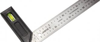
Spirit level (level) . This device is used to determine the evenness of horizontal and vertical surfaces. The length of the level can vary from 0.3 m to 2.5 m. The body of the level is made of any lightweight material, such as plastic, and is equipped with several windows.
Basic lathe tools
First, let's look at the basic turning tools for a universal lathe. A machine without this minimum set of this tool is simply a piece of unproductive iron.
Minimum set of turning tools
Jaws for a lathe, there should be at least two sets of them, reverse and straight. Keys for the lathe chuck and tool holder, check their condition to see if they are in good condition. Shims for the cutters here, the more the better, there are never too many shims, thickness from 0.3 to 8 millimeters. And the larger the dimensional gradation, the better. A rotating turning center is used to process long bar parts, and in general a turning center has many functions: tighten, center the part, guide the tap so that it goes into the center of the hole while cutting threads. The measuring tool is a caliper. ShTs-1 with a depth gauge; when processing parts over 125 mm in diameter, you will need an ShTs-2 bar. Ruler. Die holders and tap holders can be bought in the store, but often the purchased tool is not very convenient. For example, I made the die holders myself. The most necessary die holders for M8, M10, M12, M16, M20. M24. a larger size range must be selected based on production needs. Threads of larger diameter are usually cut with a cutter. Well, for accuracy, you can calibrate them later. I didn’t bother with the tap holders; I bought a universal sliding tap holder in the store. Attention! The extendable tap holder is only suitable for cutting threads up to m 20-M24. Large taps are mounted in a rigid square. Sliding ones won't hold up. For household supplies you will need: Rags, a bedside table or a rack for storing tools. Sweeping brush, hook for chips, dustpan for collecting chips. Durable gloves for chip removal. A bottle of oil for daily lubrication of the machine after work.
Additional set of turning tools
In order for a turner to perform his work on a lathe as successfully and efficiently as possible, the following types of tools and devices will be needed. A varied set of turning jaws. The larger and wider the range of turning jaws for your machine, the wider the versatility of the equipment you purchase becomes. I had 6 sets of them with different sharpenings, for processing parts such as disks and straight cams bored to different diameters. Cams bored out to clamp a part with a diameter of 10 mm will certainly leave dents on the surface of the part at the clamping point if you try to clamp parts of a larger diameter. The size of the borings is also selected based on the specifics of your production. As a rule, the turner himself will bore and select the required diameters for sharpening the cams. The emphasis is on the headstock of the lathe. To process large and small series of parts you will need a stop. The stop is a cone that is driven into the internal conical fit of the lathe spindle. A threaded screw is usually built into the stop design. Which can be adjusted to allow the part to fly out of the jaws. With the help of a stop you can get parts that are quite accurate in length. The processing speed increases significantly, and there is no need to measure the length of each workpiece.
Stops on the lathe bed. As a rule, turners are also repeatedly helped out when processing stepped parts. And trimming disc type parts. With the help of a stop on the bed, the turner will definitely not miss the length dimension on the workpiece.
Pressing rotating centers into the tailstock. A mushroom rotating center is ideal if, due to the specifics of the work, parts such as tubes and bushings are often encountered. They can tighten something that is impossible to tighten with a conventional rotating center included in the minimum set of turning tools. Based on the specifics of production, reverse rotating centers are sometimes required for operation.
The set given in our article is not complete. To it you need to add turning tools, Morse tapers, and much more. For example, I told my boss what kind of turning tool I needed for the job. And gradually he equipped his lathe with everything he needed. One could say that I have upgraded the capabilities of my machine to the fullest.
If you have any questions, call or write. My contacts are in the title of the site.
metekspert.ru
Application of measuring machines
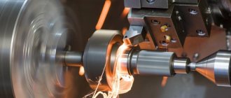
To make accurate measurements, not only hand-held measuring instruments can be used, but also special machines called coordinate measuring equipment. The peculiarity of this equipment is the ability to take measurements in three coordinates, which ensures maximum accuracy of calculations.
The design of the machines resembles a table on which working heads equipped with sensors are installed. To make a control measurement, the workpiece is placed on the table, and sensors read the parameters of the part.
Machines can capture data in two ways:
- contact, involving the use of a probe sensor;
- contactless, in which reading occurs by sending a light signal to the surface of the part.
Measuring tool for monitoring metalworking parameters :: TOCHMEKH
The most common tool for monitoring the diameters of cylindrical surfaces are calipers: ShTs-1 (with a measurement accuracy of up to 0.1 mm) or ShTs-11 (with a measurement accuracy of up to 0.05 mm).
If you need to set the size with a higher degree of accuracy, then use a micrometer, which allows you to determine the size accuracy up to 0.01 mm. When producing large batches of parts under mass production conditions, diameter control is performed using limit gauges that have two pairs of protrusions corresponding to the largest and smallest limit sizes.
A part is considered suitable if the pass-through part of the bracket fits onto the surface being measured, but the part does not pass through the non-pass-through part (Fig. 1). The lengths of stepped rollers are checked using a caliper with a retractable depth gauge (type ШЦ-1), a depth gauge, a ruler or a template. Control of the plane of the end after cutting is checked by applying the edge of a ruler or square to it; if there is no gap between the surfaces of the end and the ruler, then the end surface is processed correctly.
Rice. 1. Control of outer diameters: a - with a caliper, b - with a micrometer, c - with an indicator clamp, d - with a gauge clamp.
The perpendicularity of the end to the outer surface is determined with a square. The depth of the grooves is monitored using a depth gauge of the ShTs-1 caliper.
When turning external cylindrical surfaces and trimming the ends, various defects may occur:
- part of the surface remained untreated. Such a defect can arise due to runout of the workpiece, insufficient allowance, or mixing of the center holes;
- discrepancy between the diameters of the turned surfaces and those indicated in the drawing may occur due to incorrect setting of the cutting depth as a result of measurement errors when removing test chips or due to the fact that the backlash was not selected when setting the size using a dial;
- The linear dimensions of the treated surfaces are not maintained. This defect occurs due to incorrect installation of the stop or different positions of the workpieces in the chuck;
- non-perpendicularity of the end surface < axis of the part. Such a defect can occur for various reasons: as a result of a large protrusion of the cutter from the tool holder, due to the pressing of the cutter as a result of play in the guides of the transverse slide of the caliper, due to a large allowance;
- taper. Arises as a result of a mismatch of the axes of the centers installed in the spindle and the tailstock quill, misalignment of the rear center as a result of contamination of the conical hole in the quill, wear of the center hole, and unreliable fastening of the cutter;
- ovality. Occurs as a result of spindle runout or poor workpiece clamping;
- barreling Occurs as a result of deflection of the workpiece under the action of pressing forces or wear of the bed guides;
- saddle shape. Occurs as a result of unreliable fastening of the cutter in the tool holder or wear of the guides near the headstock;
- increased roughness of the treated surface. Occurs due to dullness of the cutter, poor machinability of the workpiece material, installation of the cutter off-center, and incorrect selection of cutting modes.
Other articles on similar topics
tochmeh.ru
Equipment operating conditions
Preserving the functionality of devices allows periodic maintenance and checks of their condition. Measuring instruments with complex design features are most susceptible to failure.
Each device comes with an instruction manual, which you should read before using it. The instructions set out all the operating rules that are relevant specifically for this model.
Automatic and electronic models of measuring machines are sensitive to temperature and air humidity. Equipment that uses a non-contact measurement method reacts especially sharply to them.
It is equally important to provide the instrument with decent storage conditions. Tools made of wood and metal are sensitive to moisture. And plastic can deform under direct sunlight and when exposed to high temperatures. Therefore, all tools should be stored in cases or boxes in a dry room.
Compliance with these rules will ensure the quality and accuracy of measurements, and will also help extend the life of the instruments.