What is cement
From the Latin “caementum” is translated as crushed stone or broken stone. This powdery material is an artificially created binder consisting of clinker, a certain amount of gypsum, mineral additives and various fillers. When cement is mixed with water or other liquids, a plastic mass is formed that, when hardened, can turn into a stone-like body.
Cement is the main component of concrete and cement-sand mortar. It has the unique ability to gain strength when exposed to moisture, which cannot be said about gypsum or air lime, which harden in dry conditions.
An interesting fact is that even the ancient Romans mixed volcanic ash or crushed stone with lime. This can be considered the beginning of the history of the appearance of cement.
Basic structures
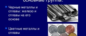
An alloy of iron and carbon is the basis of steel and cast iron, called iron alloys, and these are the most important structural materials in technology.
The structure and properties of the alloy largely depend on the characteristics of the main components and additive elements, as well as the nature of their interaction.
Pure iron is a silvery-white metal, refractory. The melting point of iron is 1539°C. iron has 2 polymorphs a and G.
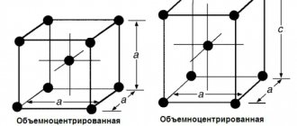
- At temperatures below 910°C, iron has a body-centered cubic lattice. This change is called A-iron. a-iron is a temperature up to 768°C (Curie point) magnetically.
When the iron is heated, the 910°C body-centered cubic lattice turns into a side-centered cubic lattice, and the A-iron turns into a G-iron. g-iron is present at a temperature of 910-1392°C
Carbon is a non-metallic element. The melting point of carbon is 3500°C. Carbon in nature exists in 2 polymorphic modifications: Diamond and graphite.
The diamond form is not found in the alloy.
In a carbon-iron alloy, the free carbon is in the form of graphite. The crystal structure of graphite is layered. Its strength and ductility are very low.
Carbon can dissolve in iron in a liquid or solid state, forming chemical compounds - cementite can be in free form in the form of graphite.
Metallurgy
Orthorhombic Fe 3 C. Iron atoms are blue.
Iron-carbon phase diagram
In iron-carbon systems (such as carbon steels and cast irons) it is a common component, since ferrite can contain no more than 0.02 wt.% Unfixed carbon. Consequently, in carbon steels and cast irons that cool slowly, part of the carbon is in the form of cementite. Cementite is formed directly from the melt in the case of white cast iron. In carbon steel, cementite is precipitated from austenite when the austenite is converted to ferrite by slow cooling, or from martensite during tempering. The intimate mixture with ferrite, another product of austenite, forms a lamellar structure called pearlite.
Although cementite is thermodynamically unstable and eventually converts to austenite (low carbon) and graphite (high carbon) at higher temperatures, it does not decompose when heated below (723 °C) into a metastable iron-carbon state. phase diagram.
Iron-carbon alloys
Iron-carbon alloys may contain the following structural components:
- Ferrite (F) is a solid solution containing carbon and other elements in iron. It has a body-centered cubic lattice. The solubility of carbon in ferrite is very low, up to 0.005% at room temperature. At 727°C, the highest solubility of 0.02% ferrite is very ductile, soft and workable by applying pressure under cold conditions.
Austenite (a) is a solid solution of carbon and other G-iron elements. It is present only at high temperatures. the maximum solubility of carbon in g-iron is 1147% at 2.14°C and 727°C at 0.8%. This temperature is the lower limit for the presence of austenite in the iron-carbon alloy. Austenite is very ductile, but harder than ferrite.
Pure form
Cementite changes from ferromagnetic to paramagnetic at its Curie temperature of approximately 480 K.
Dependence of the molar volume of cementite on pressure at room temperature.
Natural iron carbide (containing trace amounts of nickel and cobalt) occurs in iron meteorites and is called cohenite after the German mineralogist Emil Cohen who first described it. Since carbon is one of the possible minor components of light alloys of metallic cores of planets, the properties of cementite (Fe3C) as a simple substitute for cohenite are being studied experimentally. The figure shows the compression behavior at room temperature.
Components in the iron-carbon system
The components of iron-carbon alloys are iron, carbon and cementite:
Iron
Iron is a d-transition metal with a silvery-light color. Melting point – 1539° C. Specific gravity is 7.86 g/cm3. The most significant feature of iron is its polymorphism. In the solid state, iron can be found in two modifications - α and γ. Polymorphic transformations occur at temperatures of 911° C and 1392° C. At temperatures below 911° C and above 1392° C, Feα (or α-Fe) exists with a body-centered cubic lattice. In the temperature range 911…1392° C, Feγ (or γ-Fe) with a face-centered cubic lattice is stable. During the transformation α→γ, a decrease in volume is observed, since the γ-Fe lattice has a more dense packing of atoms than the α-Fe lattice. Upon cooling during the transformation γ→α, an increase in volume is observed. In the temperature range 1392…1539° C, high-temperature Feα is called Feδ. The high-temperature modification of Feα does not represent a new allotropic form.
At temperatures below 768° C, iron is ferromagnetic, and above it is paramagnetic. Point 768° C, corresponding to the magnetic transformation, i.e. The transition from a ferromagnetic state to a paramagnetic state is called the Curie point. The Feγ modification is paramagnetic.
Iron of technical purity has low hardness (80 HB) and strength (tensile strength – σв=250 MPa, yield strength – σт=120 MPa) and high plasticity characteristics (relative elongation – δ=50%, and relative contraction – ψ=80% ). Properties may vary within certain limits depending on the grain size. Iron is characterized by a high modulus of elasticity, the presence of which is also manifested in alloys based on it, providing high rigidity of parts made from these alloys.
Iron forms solutions with many elements: with metals - substitution solutions, with carbon, nitrogen and hydrogen - interstitial solutions.
Carbon
Carbon is a non-metal. It has a polymorphic transformation, depending on the conditions of formation, it exists in the form of graphite with a hexagonal crystal lattice (melting point - 3500 ° C, density - 2.5 g / cm3) or in the form of diamond with a complex cubic lattice with a coordination number of four (melting point – 5000° C).
In iron-carbon alloys, carbon is in a state of solid solution with iron and in the form of a chemical compound - cementite (Fe3C), and also in a free state in the form of graphite (in gray cast iron).
Cementite
Cementite (Fe3C) is a chemical compound of iron and carbon (iron carbide), contains 6.67% carbon. More precise studies have shown that cementite can have a variable carbon concentration. However, in the future, when analyzing the phase diagram, we will make the assumption that Fe3C has a constant composition. The crystal lattice of cementite is rhombic, specific gravity 7.82 g/cm3 (very close to the specific gravity of iron). At high temperatures, cementite dissociates, so its melting point is unclear and is approximately 1260° C. It does not experience allotropic transformations. The crystal lattice of cementite consists of a series of octahedra, the axes of which are inclined to each other. At low temperatures, cementite is weakly ferromagnetic, losing its magnetic properties at a temperature of about 210° C. Cementite has high hardness (more than 800 HB, easily scratches glass), but extremely low, almost zero, ductility.
Cementite is capable of forming substitutional solid solutions. Carbon atoms can be replaced by non-metal atoms: for example, nitrogen; iron atoms - metals: manganese, chromium, tungsten, etc. Such a solid solution based on a cementite lattice is called alloyed cementite.
If graphite is a stable phase, then cementite is a metastable phase. Cementite is an unstable compound and, under certain conditions, decomposes to form free carbon in the form of graphite. This process is of great practical importance in the formation of the structure of cast iron.
Excerpt characterizing Cementite
The people of the Russian army were so exhausted by this continuous movement of forty miles a day that they could not move faster. To understand the degree of exhaustion of the Russian army, you only need to clearly understand the significance of the fact that, having lost no more than five thousand people wounded and killed during the entire movement from Tarutino, without losing hundreds of people as prisoners, the Russian army, which left Tarutino numbering one hundred thousand, came to Red in the number of fifty thousand. The rapid movement of the Russians after the French had just as destructive an effect on the Russian army as the flight of the French. The only difference was that the Russian army moved arbitrarily, without the threat of death that hung over the French army, and that the backward sick of the French remained in the hands of the enemy, the backward Russians remained at home. The main reason for the decrease in Napoleon's army was the speed of movement, and the undoubted proof of this is the corresponding decrease in Russian troops. All of Kutuzov’s activities, as was the case near Tarutin and near Vyazma, were aimed only at ensuring, as far as was in his power, not to stop this movement disastrous for the French (as the Russian generals wanted in St. Petersburg and in the army), but assist him and facilitate the movement of his troops. But, in addition, since the fatigue and huge loss that occurred in the troops due to the speed of movement appeared in the troops, another reason seemed to Kutuzov to slow down the movement of the troops and to wait. The goal of the Russian troops was to follow the French. The path of the French was unknown, and therefore the closer our troops followed on the heels of the French, the greater the distance they covered. Only by following at a certain distance was it possible to cut the zigzags that the French were making along the shortest path. All the skillful maneuvers that the generals proposed were expressed in the movements of troops, in increasing the transitions, and the only reasonable goal was to reduce these transitions. And Kutuzov’s activity was directed towards this goal throughout the entire campaign, from Moscow to Vilna - not by chance, not temporarily, but so consistently that he never betrayed it. Kutuzov knew not with his mind or science, but with his whole Russian being, he knew and felt what every Russian soldier felt, that the French were defeated, that the enemies were fleeing and it was necessary to see them out; but at the same time, he felt, along with the soldiers, the full weight of this campaign, unheard of in its speed and time of year. But to the generals, especially not Russians, who wanted to distinguish themselves, to surprise someone, to take some duke or king prisoner for something - it seemed to the generals now, when every battle was disgusting and meaningless, it seemed to them that now was the time fight and defeat someone. Kutuzov only shrugged his shoulders when, one after another, he was presented with plans for maneuvers with those poorly shod, without sheepskin coats, half-starved soldiers, who in one month, without battles, had melted to half and with whom, under the best conditions of ongoing flight, it was necessary to go to the border the space is larger than that which was traversed.
State diagram
Line ABCD is the liquidus of the system, line AHJECF is the solidus.
Since iron, in addition to forming the chemical compound Fe3C with carbon, has two allotropic forms α and γ, the following phases exist in the system:
liquid (liquid solution of carbon in iron) existing above the liquidus line, designated everywhere by the letter L;
cementite Fe3C - line DFKL, further denoted by chemical formula or letter C;
ferrite is a structural component that is α-iron, which dissolves carbon in small quantities; denoted by the letter Ф, α or α-Fe. The ferrite region in the iron-carbon system is located to the left of the GPQ and AHN line;
Austenite is a structure that is a solid solution of carbon in γ-iron. The austenite region in the diagram is NJESG. It is designated austenite A, or γ-Fe.
The three horizontal lines in the diagram (HJB,ECF and PSK) indicate the occurrence of three invariant reactions.
At 1499 °C (HJB line) a peritectic reaction occurs:
As a result of the peritectic reaction, austenite is formed. This reaction is observed only in alloys containing carbon from 0.1 to 0.5%. At 1147 °C (horizontal ECF), a eutectic reaction occurs:
As a result of this reaction, a eutectic mixture is formed. A eutectic mixture of austenite and cementite is called ledeburite (German scientist Ledebur)
This reaction occurs in all alloys of the system containing more than 2.14% carbon.
At 727 °C (horizontal PSK) a eutectoid reaction occurs
The transformation product is an ectectoid mixture. A eutectoid mixture of ferrite and cementite is called pearlite and has the appearance of mother-of-pearl, which is why this structure got its name.
All alloys containing more than 0.02% carbon, i.e., almost all industrial iron-carbon alloys, undergo pearlite (eutectoid) transformation.
There are three groups of steels: eutectoid, containing about 0.8% C, the structure of which consists only of pearlite; hypoeutectoid, containing less than 0.8% C. The structure of which consists of ferrite and pearlite, and hypereutectoid, containing from 0.8 to 2.14% C, the structure of which consists of pearlite and cementite.
Links[edit]
- ^ ab Smith and Hashemi 2006, p. 363
- Durand-Charre 2003 harvnb error: no target: CITEREFDurand-Charre2003 (help)
- HKDH Bhadeshia (2020). "Cementite". International Materials Reviews
.
65
(1): 1-27. DOI: 10.1080/09506608.2018.1560984. - Ashrafzadeh, Milad; Soleimani, Amir Peyman; Panjepur, Masud; Shamanian, Morteza (2015). "Formation of cementite from a hematite-graphite mixture by simultaneous thermo-mechanical activation". Metallurgical and Materials Transaction B
.
46
(2):813–823. DOI: 10.1007/s11663-014-0228-3. S2CID 98253213. - Smith & Hashemi 2006, pp. 366-372
- S. W. Smith; W. White; S. G. Barker (1911). "Magnetic transition temperature of cementite". Proc. Phys. Soc. London
.
24
(1): 62–69. DOI: 10.1088/1478-7814/24/1/310. - Vagn F. Buchwald, Handbook of Iron Meteorites, University of California Press 1975
- Gunnar Hägg, Z. Christ.
, Vol. 89, p. 92-94, 1934. - Smith, William F. (1981). Structure and properties of engineering alloys
. New York: McGraw-Hill. pp. 61–62. ISBN 978-0-07-0585607. - Mannix, Liam (2019-08-31). “This meteorite came from the core of another planet. There's a new mineral inside." Age
. Retrieved September 14, 2022.
Free cementite
Free cementite (Fe3C), which is formed when there is insufficient silicon, too much manganese and sulfur.
Structurally free cementite is undesirable.
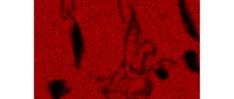
Structurally free cementite, X 500: a – before deformation, 6 – after deformation.
Decomposition of structurally free cementite is achieved by heating and holding the casting above a critical interval; The heating temperature and holding time depend on the composition of white cast iron in terms of carbon content (Fig.
The amount of structurally free cementite. Inclusions of structurally free cementite located along the boundaries of ferrite grains (Fig. Inclusions of structurally free cementite coagulated and located inside ferrite grains are less dangerous. The scale is built according to the increasing size of cementite inclusions and the development of its distribution in the form of a network or chain.
Decomposition of structurally free cementite is achieved by heating and holding the casting above a critical interval; The heating temperature and holding time depend on the composition of white cast iron in terms of carbon content (Fig.
Particles of structurally free cementite should be small, as evenly dispersed as possible (Fig. Small particles of cementite are obtained at low temperatures of winding hot-rolled strip into a roll, and large ones - at high temperatures, when they have time not only to separate from the solid solution in ferrite, but also to reach large sizes due to coagulation and growth.
The amount of structurally free cementite in steel is determined by scores based on reference samples of microstructures.
In addition to structurally free cementite, there is also tertiary cementite at the boundaries of ferrite grains. It is impossible to prevent its release during the final heat treatment, since for this purpose the sheets for deep drawing must be cooled slowly.
Structurally free cementite is not allowed. Eutectic graphite and ferrite are allowed in the form of separate small inclusions in an amount of no more than 5% of the section area for each inclusion. The casting fracture must have a uniform fine-grained structure with a matte tint.
SE), the free cementite present in it will completely dissolve in austenite and the structure will become homogeneous.
Hypoeutectoid steels do not contain structurally free cementite.
C) Cast irons with structurally free cementite are classified as white cast irons. Ferrite may appear in them as a result of annealing, but such cast iron is not ferritic.
Structurally free cementite is not allowed in low carbon steel. It is formed as a result of slow cooling after rolling or heat treatment and, located along the grain boundaries, sharply reduces the plastic properties. This causes large rejects during cold heading.
Chemical properties
As a chemical compound, cementite has its own physical, chemical and mechanical characteristics. It has a gray crystalline appearance at fracture and is relatively hard with high thermal stability. The main chemical properties of cementite are expressed in the following indicators:
- chemical formula Fe3C;
- decomposition of the structure occurs at temperatures above 1650°C;
- exposed to various acids (especially highly concentrated ones);
- quickly reacts with oxygen.
Based on the existing chemical properties, physical and mechanical properties are formed. The main physical properties include:
- melting point is 1700 °C;
- molecular weight is 179.55 amu;
- The density of cementite is 7.7 g/cm3 at a temperature of 20 °C.
The main mechanical properties include:
- hardness;
- resistance to impact (fragility);
- fracture resistance;
- plastic.
The hardness of this compound reaches high values and is equal to HB 8000 MPa or HRC 70. However, it has sufficient brittleness and low ductility.
Possessing the listed properties, cementite is actively used in the production of cast parts for various purposes. The formation of various types of cementite and its compounds with other forms leads to a change in the characteristics of the resulting steel or cast iron, therefore, to an improvement or decrease in individual consumer properties.
For example, to obtain white cast iron and give it high strength and ductility, they try to convert cementite into graphite. This is achieved during the annealing operation. As the temperature increases, it breaks down into two components: ferrite and graphite.
Depending on the required properties, they try to maintain the required amount of cementite in cast iron. This is especially true for the so-called free fraction of this compound. To reduce its concentration, various methods of chemical and thermal treatment are used. To solve this problem, use a solution of nitric acid in pure alcohol. Structurally free cementite precipitates as a result of boiling a cast iron pig in this solution. In addition, three types of processing are used: annealing, normalizing and hardening.
Technical iron contains tertiary cementite in combination with ferrite. It appears along the ferrite boundary at carbon contents from 0.01% to 0.025%. To improve the quality of steel, they try to reduce the content of free cementite. Its concentration is especially observed in soft steel grades. The content of this mixture and perlite per unit volume has a great influence on the quality of stamping. Excessive presence of tertiary cementite, especially in the form of a long chain or network, leads to the formation of breaks during stamping. Therefore, to obtain good forging steel, they try to reduce the amount of tertiary cementite. The structure of such formations should not exceed the second point on the established scale. The resulting hardness should not exceed HB 50 units.
Pure iron
Cementite © is a carbonized compound of iron and carbon (fe3c). Cementite contains 6.67% carbon. The melting point of cementite is about 1600°C. It has a complex crystal lattice. Iron is the hardest and most brittle component of a carbon alloy. Cementite is unstable; under certain conditions, the reaction Fe3C> 3Fe + C causes the formation and decomposition of free carbon in the form of graphite.
The more cementite in an iron-carbon alloy, the higher the hardness.
Graphite is an allotrope of carbon. Graphite is soft and its strength is very low. Cast iron and graphitized steel are included in the composition in the form of inclusions of various shapes.
The shape of graphite inclusions affects the mechanical and technical properties of the alloy.
Perlite (P) is a mechanical mixture of ferrite and cementite containing 0.8% carbon. It is formed during recrystallization (collapse) of austenite at a temperature of 727°C. this decomposition is called eutectoid, and pearlite-eutectoid. Pearlite has high strength and hardness, which increases the mechanical properties of the alloy.
- Redebrite is a mechanical mixture of austenite and cementite containing 4.3% carbon. It is formed as a result of eutectic transformation at a temperature of 1147 ° C. At a temperature of 727 ° C, austenite turns into pearlite, and after cooling, the red briquette turns into a mixture of pearlite and cementite. Redebrite has high hardness and excellent brittleness. Everything white is part of cast iron.
Chemical compounds
The main structures that make up iron-carbon alloys:
Ferrite is a solid solution of carbon in α-Fe. At 723°C the maximum carbon content is 0.02%.It will not corrode if there are any impurities.
Cementite is a compound containing iron carbon fe3c-6.67% carbon carbide. The eutectic is an integral part of the mixture and an independent structural component. Due to the substitution of atoms of other metals, a solid solution can be formed, which is unstable and decomposes during heat treatment. Cementite is very hard (HB 800) and brittle.
Austenite is a solid solution of carbon in γ-Fe. Carbon atoms are introduced into the crystal lattice, and the degree of saturation can vary depending on temperature and impurities. It is stable only at high temperatures, and stable even at normal low temperatures - impurities of Mn, Cr. Austenitic hardness HB 170… 220.
Microstructure:
- a-hypereutectoid steel-ferrite (light area) and pearlite (dark area) at 500X magnification, b-eutectoid steel-perlite (1000'), c-eutectoid steel-interlocking pearlite and cementite (200').)
- The solubility of carbon in ferrite decreases from 727% at 0.02°C to 0.005% at room temperature.
Description
The carbon concentration in cementite—6.67% by weight—is the limit for iron-carbon alloys.
Cementite is a metastable phase; the formation of a stable phase—graphite—is difficult in many cases. Cementite has an orthorhombic crystal lattice, is very hard and brittle, and weakly magnetic up to 210 °C. Depending on the conditions of crystallization and subsequent processing, cementite can have different shapes - equiaxed grains, a network along grain boundaries, plates, as well as a Widmanstätt structure.
Cementite in different quantities, depending on the concentration, is present in iron-carbon alloys even at low carbon contents. Formed during the process of crystallization from molten cast iron. In steels it is released when austenite is cooled or martensite is heated. Cementite is a phase and structural component of iron-carbon alloys, an integral part of ledeburite, perlite, sorbite and troostite. Cementite is a representative of the so-called interstitial phases, compounds of transition metals with light metalloids. In the interstitial phases, the proportion of both covalent and metallic bonds is high.
Brinell hardness is more than 800 kg/mm2. Primary cementite crystallizes from a liquid alloy Secondary cementite - from austenite Tertiary cementite - from ferrite
Cementite unstable connection
At a carbon content of 0.8% and a temperature of 727°C, all austenite decomposes and turns into a mechanical mixture of ferrite and cementite-pearlite. Steel containing 0.8% carbon is called eutectoid. Steel containing 0.02-0.8% carbon is called po-eutectoid and 0.8-2.14% carbon-po-eutectoid.
At a temperature corresponding to the PSK line, the austenite remaining in the system alloy decomposes to form pearlite, a mechanical mixture of ferrite and cementite. PSK line is called pearlite conversion line.
At a temperature corresponding to the SE line, austenite is saturated with carbon, and as the temperature decreases, excess carbon (secondary) is released in the form of cementite.
- Vertical DFKL means that the chemical composition of the cementite does not change. Only the shape and size of the crystals change, which significantly affects the properties of the alloy. The largest cementite crystals are formed when they are separated from the liquid during the process of primary crystallization. White cast iron with 4.3% carbon is called eutectic. White cast iron with a carbon content of 2.14-4.3% is called overheated, and 4.3-6.67% is called overheated.
General information about the alloy
A distinctive property of steel is the presence of special alloyed impurities and carbon in the structure. Actually, the hypoeutectoid alloy is determined by the carbon content
Here it is important to distinguish between classical eutectoid and ledeburite steels, which have much in common with the described type of industrial iron. If we consider the structural class of steel, then the hypoeutectoid alloy will be classified as eutectoids, but containing alloyed ferrites and pearlites. The fundamental difference from hypereutectoids is the carbon level below 0.8%
Exceeding this indicator allows steel to be classified as a full-fledged eutectoid. In some ways, the opposite of hypoeutectoid is hypereutectoid steel, which, in addition to pearlite, also contains secondary carbide impurities. Thus, there are two main factors that make it possible to distinguish hypoeutectoid alloys from the general group of eutectoids. Firstly, it is a relatively low carbon content, and secondly, it is a special set of impurities, the basis of which is ferrite
The fundamental difference from hypereutectoids is the level of carbon, which is below 0.8%. Exceeding this indicator allows steel to be classified as a full-fledged eutectoid. In some ways, the opposite of hypoeutectoid is hypereutectoid steel, which, in addition to pearlite, also contains secondary carbide impurities. Thus, there are two main factors that make it possible to distinguish hypoeutectoid alloys from the general group of eutectoids. Firstly, it is a relatively low carbon content, and secondly, it is a special set of impurities, the basis of which is ferrite.
Materials for the production of silicate concrete
The main binder component in silicate concrete is finely ground lime or fluffed lime, which, in combination with aggregates, constitutes the main raw material for the production of silicate concrete. After adding water and subsequent heat treatment in autoclaves, the silicate concrete mixture turns into a durable concrete product.
Lime used for the production of silicate mixtures must meet the following properties:
- average hydration rate;
- moderate exothermic effect;
- the entire fraction must be equally fired;
- MgO less than 5%;
- Lime slaking time: no more than 20 minutes.
Underburning of the lime mass leads to increased consumption of material. Overburning reduces the hydration time of lime, which leads to swelling, cracks on the surface of products, etc.
Lime
Lime used for the production of silicate concrete is usually used in the form of finely ground lime mixtures of the following composition:
- calcareous-siliceous - a combination of lime and quartz sand;
- lime-slag (lime and blast furnace slag);
- lime-ash - fuel oil shale or coal ash and lime;
- lime-expanded clay and other similar components obtained from industrial waste of porous aggregates;
- lime-belite binders obtained by low-temperature firing of a lime-siliceous dry mixture and quartz sand.
The following materials are used as siliceous fillers:
- quartz ground sand;
- metallurgical (blast furnace) slag;
- thermal power plant ash.
Most often, quartz sands of medium and fine fractions are used as fillers, which in their composition should look like this:
- 80% or more silica;
- less than 10% clay inclusions;
- 0.5% or less mica impurities.
Large inclusions of clay in the structure of quartz sand reduce the frost resistance and strength of silicate concrete.
Quartz sand
Finely ground quartz sand has a significant influence on the formation of high performance properties of silicate concrete. Thus, with increasing dispersion of sand particles, the frost resistance, strength and other characteristics of silicate materials increase.
When choosing components for the production of silicate concrete, you need to know the following:
- Binder consumption increases in proportion to the increase in concrete strength.
- A decrease in the consumption of binders in the silicate mixture is observed with an increase in the dispersion of fine quartz sand, and increases with an increase in the molding humidity of the silicate concrete solution.
- The dispersion of ground quartz sand should be 2.5 times lower than the dispersity of ground lime.
Corrosion resistance
Destructive processes in cement stone occur due to the interaction of its components with acids and salts contained in water. Chemical compounds may dissolve in a liquid or crystallize. In any case, they lead to destruction due to the occurrence of internal stress. To protect against corrosion you need:
- approach the choice of cement responsibly;
- reduce the porosity of the material;
- waterproof cement;
- introduce pozzolanic additives into the composition of building materials.
Properties of silicate concrete
The main properties of silicate concrete are represented by the following indicators:
- Water absorption of silicate products, depending on the method of compacting the concrete mixture, is 10–18%.
- The frost resistance of high-strength silicate concrete reaches 100 cycles or more.
- High corrosion resistance - these parameters differ slightly from those of cement concrete.
- Heat resistance.
- Resistance to temperature and atmospheric influences.
- Low cost of production of finished products.
- Durability (up to 70 years).
Grinding degree/grinding
This property determines how long it will take for the cement to harden, and what strength this hardened material will have. It is better to choose fine grinding, since it is in this material that the reaction between cement and water quickly occurs and strength increases. But the finest degree of grinding has the opposite result - the cement’s need for water increases, and sedimentary deformations occur. All this entails a decrease in the strength of cement. In order not to make a mistake, builders recommend that the cement contain both large particles - 80 microns, and small ones - about 40 microns. To save money, you can add ultrafine cement to regular coarse cement. It is enough for the latter to be 15-25%.
Heat treatment General provisions for heat treatment
Heat treatment consists of heating to a certain temperature and subsequent cooling to cause the desired change in the structure of the metal.
The main influencing factors during heat treatment are temperature and time, therefore the mode of any heat treatment can be represented by a graph in coordinates t (temperature) - (time).
The heat treatment mode is characterized by the following main parameters:
— heating temperature tmax, i.e. the maximum temperature to which the alloy was heated during heat treatment;
— holding time of the alloy at heating temperature в;
— heating rate Vheat;
— cooling rate Vcool.
If heating (or cooling) occurs at a constant speed, then in temperature-time coordinates it is characterized by a straight line with a certain, constant angle of inclination.
Heat treatment can be complex, consisting of multiple heatings, intermittent or stepwise heating (cooling), cooling to negative temperatures, etc. Such heat treatment can be depicted in temperature-time coordinates.
Any heat treatment process can be characterized by a temperature-time graph.
Materials for the production of silicate concrete
The main binder component in silicate concrete is finely ground lime or fluffed lime, which, in combination with aggregates, constitutes the main raw material for the production of silicate concrete. After adding water and subsequent heat treatment in autoclaves, the silicate concrete mixture turns into a durable concrete product.
Lime used for the production of silicate mixtures must meet the following properties:
- average hydration rate;
- moderate exothermic effect;
- the entire fraction must be equally fired;
- MgO less than 5%;
- Lime slaking time: no more than 20 minutes.
Underburning of the lime mass leads to increased consumption of material. Overburning reduces the hydration time of lime, which leads to swelling, cracks on the surface of products, etc.
Lime
Lime used for the production of silicate concrete is usually used in the form of finely ground lime mixtures of the following composition:
- calcareous-siliceous - a combination of lime and quartz sand;
- lime-slag (lime and blast furnace slag);
- lime-ash - fuel oil shale or coal ash and lime;
- lime-expanded clay and other similar components obtained from industrial waste of porous aggregates;
- lime-belite binders obtained by low-temperature firing of a lime-siliceous dry mixture and quartz sand.
The following materials are used as siliceous fillers:
- quartz ground sand;
- metallurgical (blast furnace) slag;
- thermal power plant ash.
Most often, quartz sands of medium and fine fractions are used as fillers, which in their composition should look like this:
- 80% or more silica;
- less than 10% clay inclusions;
- 0.5% or less mica impurities.
Large inclusions of clay in the structure of quartz sand reduce the frost resistance and strength of silicate concrete.
Quartz sand
Finely ground quartz sand has a significant influence on the formation of high performance properties of silicate concrete. Thus, with increasing dispersion of sand particles, the frost resistance, strength and other characteristics of silicate materials increase.
When choosing components for the production of silicate concrete, you need to know the following:
- Binder consumption increases in proportion to the increase in concrete strength.
- A decrease in the consumption of binders in the silicate mixture is observed with an increase in the dispersion of fine quartz sand, and increases with an increase in the molding humidity of the silicate concrete solution.
- The dispersion of ground quartz sand should be 2.5 times lower than the dispersity of ground lime.
Primary, secondary and tertiary cementite
According to the method and field of education, it is divided into three main types:
- primary;
- secondary;
- tertiary.
The formation of primary cementite is observed during the crystallization of hypereutectic cast iron. At this moment, elongated crystals form. They form primary carbide. Primary formation can manifest itself in hypoeutectic cast iron in the composition of ledeburite during the crystallization of the melt. Studies have shown that this mixture of iron and carbon is present not only in white cast iron. It can appear in gray cast iron after completion of the so-called graphitization operation.
The process of formation of the secondary type is observed mainly during cooling of austenite. This phenomenon is observed when the temperature drops below 1147 °C. At this temperature, the carbon concentration in austenite decreases. The released carbon atoms enter into new bonds, and cementite is formed, which is called secondary. With a further decrease in temperature to eutectoid, its formation continues. Even at room temperature it is found in perlite. Under these conditions it can be found in hypereutectoid steel. It forms at the boundaries of the granular structure.
The cooling process of ferrite forms what is called tertiary cementite. This species is quite difficult to record, and further monitoring of its formation is being carried out. This problem is associated with the appearance of tertiary cementite in small quantities. Studies of the formation of this fraction have shown that it takes on several forms: plates, veins or in the form of needles. All these elements are formed in ferrite grains. Tertiary formation is quite difficult to obtain because as the percentage of carbon increases, tertiary cementite combines with perlite. As the cooling rate increases, the carbon content is retained in the metal solution and the formation of the tertiary fraction stops. A clear sign of formation is the result of gradual aging of ferrite. In this case, the carbon concentration in the ferrite content changes.
From the above description the following conclusions can be drawn:
- the primary fraction is formed as a result of crystallization of the melt;
- secondary – as a result of sequential cooling of austenite;
- tertiary – after cooling the ferrite.
In different grades of steel and cast iron, primary cementite has a high variability of shape. These can be plates of regular strip shape or needle-shaped formations. During the annealing operation, it can take the form of rounded formations. As a result, it transforms into granular perlite.
Chemical properties
As a chemical compound, cementite has its own physical, chemical and mechanical characteristics. It has a gray crystalline appearance at fracture and is relatively hard with high thermal stability. The main chemical properties of cementite are expressed in the following indicators:
- chemical formula Fe3C;
- decomposition of the structure occurs at temperatures above 1650°C;
- exposed to various acids (especially highly concentrated ones);
- quickly reacts with oxygen.
Based on the existing chemical properties, physical and mechanical properties are formed. The main physical properties include:
- melting point is 1700 °C;
- molecular weight is 179.55 amu;
- The density of cementite is 7.7 g/cm3 at a temperature of 20 °C.
The main mechanical properties include:
- hardness;
- resistance to impact (fragility);
- fracture resistance;
- plastic.
The hardness of this compound reaches high values and is equal to HB 8000 MPa or HRC 70. However, it has sufficient brittleness and low ductility.
Possessing the listed properties, cementite is actively used in the production of cast parts for various purposes. The formation of various types of cementite and its compounds with other forms leads to a change in the characteristics of the resulting steel or cast iron, therefore, to an improvement or decrease in individual consumer properties.
For example, to obtain white cast iron and give it high strength and ductility, they try to convert cementite into graphite. This is achieved during the annealing operation. As the temperature increases, it breaks down into two components: ferrite and graphite.
Depending on the required properties, they try to maintain the required amount of cementite in cast iron. This is especially true for the so-called free fraction of this compound. To reduce its concentration, various methods of chemical and thermal treatment are used. To solve this problem, use a solution of nitric acid in pure alcohol. Structurally free cementite precipitates as a result of boiling a cast iron pig in this solution. In addition, three types of processing are used: annealing, normalizing and hardening.
Technical iron contains tertiary cementite in combination with ferrite. It appears along the ferrite boundary at carbon contents from 0.01% to 0.025%. To improve the quality of steel, they try to reduce the content of free cementite. Its concentration is especially observed in soft steel grades. The content of this mixture and perlite per unit volume has a great influence on the quality of stamping. Excessive presence of tertiary cementite, especially in the form of a long chain or network, leads to the formation of breaks during stamping. Therefore, to obtain good forging steel, they try to reduce the amount of tertiary cementite. The structure of such formations should not exceed the second point on the established scale. The resulting hardness should not exceed HB 50 units.
Phases and structures on the iron-cementite phase diagram
Phase diagrams are plotted in “concentration – temperature” coordinates and provide a visual representation of the phase composition of alloys; structural transformations that occur during heating and cooling; are used to select the temperature during heat treatment, etc. To analyze the transformations occurring in steels and cast irons, the iron-cementite phase diagram is of utmost importance (Fig. 28.1).
Rice. 28.1. Iron-cementite phase diagram
In this diagram, ABCD is the liquidus line; below it crystallization begins. The point with the minimum crystallization (melting) temperature, corresponding to 4.3% C, is called eutectic (from the Latin “low-melting point”), after solidification of the alloy the structure of ledeburite corresponds to it. A similar point at 0.81% C, where the transformation occurs in solid form, is called the eutectoid, and the pearlite structure corresponds to it. AHJECFD – solidus line; At this line, crystallization ends, and below it all the formed phases are solid.
The iron-cementite phase diagram combines 6 structural components, including 4 phases (liquid, ferrite, austenite, cementite) and 2 mechanical mixtures (perlite and ledeburite).
Ferrite
(F) is a solid solution of carbon in α-iron. This is the softest and most flexible structural component. The limiting carbon content in ferrite at 727 °C (point P) is about 0.02%, and at room temperature (point Q) - 0.01%.
Austenite
(A) is a solid solution of carbon in γ-iron. This is a harder and more durable structural component. Exists at temperatures above 727 °C. The limiting carbon content (point E) is 2.14%.
Cementite
(C) - iron carbide - a chemical compound Fe3C (6.67% C) with a complex crystal lattice consisting of a series of octahedra (Fig. 28.2), and is the hardest and most fragile structural component. Based on their origin, they distinguish primary cementite CI - released from the liquid along the CD line, secondary CII - from austenite along the ES line, tertiary CIII - from ferrite along the PQ line.
Perlite
[34] (P) is a mechanical mixture of ferrite and cementite, containing on average 0.81% C. Due to the presence of cementite, it is stronger and harder than ferrite and austenite.
Ledeburite
[35] (L) is a mechanical mixture of ferrite and cementite, containing on average 4.3% C. Due to the larger proportion of cementite, it is harder and more brittle than pearlite.
Lecture No. 3. Iron-carbon alloys
Lecture No. 3. Iron-carbon alloys
Iron-carbon alloys (steels and cast irons) are the most common materials. These are called ferrous metals and make up about 95% of metal production. The state diagram of iron-carbon alloys gives an idea of the structure of steels and cast irons.
3.1. Iron–carbon phase diagram
Before considering transformations in the alloys of this system, let us consider the properties and structure of the components and phases of the system, as well as the areas of their existence.
Components of the Fe–C system
.
Pure iron (Fe)
is a silvery-white polymorphic metal, with a density γ = 7.86 g/cm3, atomic number 26, atomic weight 55.85, melting point 1539°C, and has a low hardness HB80. When heated, iron undergoes polymorphic transformations (Fig. 1.9) and has two polymorphic modifications Feα and Feγ.
Carbon (C)
– non-metallic polymorphic element (graphite and diamond), with a density of 2.25 g/cm3.
Phases of the Fe–C system
. All alloys are combined from three single-phase and two two-phase structural components.
Single-phase structural components
.
Ferrite
is a solid solution of carbon intercalation in Fα, designated Feα(C) – F. The maximum solubility of carbon in ferrite reaches 0.02% at 727°C and 0.006% at 20°C. Ferrite is white crystals; its properties are close to those of commercially pure iron. The region of existence of ferrite is QPG.
Austenite
– solid solution of carbon intercalation in Feγ. It is designated Feγ(C) – A. It dissolves carbon well, at t = 1147°C it contains 2.14% C, and at = 727°C – 0.8% C. Austenite is a paramagnetic, plastic phase. Austenite region NJESG.
Cementite
(C) - chemical compound Fe3C - iron carbide, formed at a carbon content of 6.67%. Melting point 1600°C. It has a white, shiny color, brittle, hard. Can be primary, secondary, tertiary. DFKL cementite area.
There is also a liquid phase located above the liquidus line. Iron dissolves carbon well, forming a homogeneous liquid phase - F.
Two-phase structural components
.
Ledeburite
is a eutectic of the Fe – Fe3C system, it is a mechanical mixture of cementite and austenite and contains 4.3% C. Crystallizes at t = 1147°C, denoted by L. Eutectic reaction: JC↔LC(AE + CF). At a temperature of 727°C, the eutectoid transformation of ledeburite occurs, and its structure will be LS(PS + C)
Perlite –
The eutectoid of the Fe system - Fe3C - is a mechanical mixture consisting of small plates of cementite in a ferrite base. It is designated as P. Pearlite is formed from a single-phase solution of Feγ(C) during the polymorphic transformation Feγ→ Feα at a temperature t = 727°C and a carbon concentration of 0.8%.
Feγ(C)0.8%→ Fe3C6.67% + Feα(C)0.025%
Iron, interacting with carbon, forms a number of chemical compounds: Fe3C, Fe2C, FeC, etc. Since a chemical compound in phase diagrams can be considered as a component, the iron-carbon diagram is usually depicted only up to a carbon content of 6.67%, at which it is formed iron carbide Fe3C (stable chemical compound). Since only this part of the iron-carbon diagram is of practical importance, this part of the diagram is called the iron-cementite phase diagram.
Rice. 3.1. Iron-carbon phase diagram (iron-cementite)
Line ABCD is the liquidus line
(S), line AHJECD -
solidus line
(L) of the iron-cementite system. Along the ECF line, at t = 1147°C, the eutectic transformation AE+ CF → LC occurs, i.e., a eutectic—ledeburite—is formed.
Along the PSK line, the eutectoid transformation FP + CK → PS occurs, that is, the eutectoid of the system is formed - pearlite. Austenite is suitable for the PSK line with a concentration of 0.8% C. If the carbon concentration is less than 0.8%, then ferrite is precipitated from austenite along the GS line; if it is higher, then secondary cementite, CII, is precipitated along the ES line. Line PQ is a line of variable solubility of carbon in the ferrite lattice. Excess carbon forms with iron the chemical compound Fe3C - cementite. To note the peculiarities of the release of cementite in alloys with a carbon concentration of less than 0.025%, it is designated tertiary cementite - CIII. It is released in the form of dispersed inclusions in ferrite grains, increasing its strength.
The temperatures at which phase and structural transformations occur in alloys of the Fe – Fe3C system, i.e. critical points, have a symbol. All critical points are designated by the letter A. When heated, the letter “c” is added to A, that is, Ac, and when cooled, “r” is added, that is, Ar.
The first critical point A1 lies on the PSK line (727°C) and corresponds to the transformation P ↔ A; A2 corresponds to a temperature of 768°C - the Curie point, A3 - the GS line along which the F↔A transformation occurs, the temperature of which depends on the carbon concentration in the alloy, Аcm - the SE line - the beginning of the release of CII.
All alloys of the Fe-Fe3C system are divided into two large groups according to their structural characteristics: steels and cast irons.
Carbon steels
are called alloys of iron and carbon up to a concentration of 2.14% C. This is a theoretical definition. In practice, steels generally do not contain more than 1.5% carbon. They are divided into: hypoeutectoid steels - (containing from 0.025% to 0.8% C, F + P), eutectoid - (0.8% C, P), hypereutectoid - (0.8%...2.14% C, P + CII), Fig. 3.2.
a B C
Rice. 3.2. Microstructures of carbon steels:
a – hypoeutectoid; b – eutectoid; c – hypereutectoid
In hypoeutectoid steel, ferrite is revealed in the microstructure in the form of light fields, and pearlite - in the form of fields of a banded (dark) structure (Fig. 3.2a), where the general light background is ferrite, and the dark places are shadows from protruding cementite plates.
The amount of pearlite in the steel structure increases in proportion to the increase in carbon content, this occurs up to a carbon content of 0.8%, when it becomes the only structural component of eutectoid steel (Fig. 3.2b).
The microstructure of hypereutectoid steel consists of pearlite and secondary cementite, which, upon slow cooling, precipitates in the form of a network along the boundaries of pearlite grains (Fig. 3.2c).
Alloys of iron and carbon containing more than 2.14% carbon (up to 6.67%) are called cast iron
. They are divided into hypoeutectic (2.14%...4.3% C, P + CII+ L(P + C)), eutectic (4.3% C, L(P + C)) and hypereutectic (4.3% C …6.67%C, CI+ L(P + C)) (Fig. 3.3).
a B C
Rice. 3.3. Microstructures of cast iron:
a – hypoeutectic; b – eutectic; c – hypereutectic
In addition, technically pure iron is isolated (up to 0.025% C, F + CIII).
When iron-carbon alloys are cooled, carbon can not only react chemically with iron, but also be released in the form of graphite. In other words, a liquid solution, ferrite and austenite can be in equilibrium not only with cementite, but also with graphite, and then the phase diagram will be iron - graphite.
Cementite is a less stable phase than graphite G, therefore the Fe – Fe3C diagram is unstable, metastable, and Fe – G is stable. The process of graphite formation is called graphitization. Graphitization is more pronounced on the right side of the diagram and leads to the formation of half- or gray cast irons, which have graphite in their structure, in contrast to white cast irons, which contain only cementite in their structure.
3.2. Carbon and permanent impurities in steel, their effect on its properties
The phase composition of any steel in an equilibrium state is ferrite + cementite. The amount of cementite increases in proportion to the increase in carbon content, and since cementite is a hard, brittle phase, the strength properties of steel increase (up to 0.9% C), hardness, and ductility and impact strength decrease. With an increase in carbon content, technological properties deteriorate - weldability, machinability, and deformability in hot and cold states decrease. For every 0.1% C, the cold brittleness threshold increases by 20°C. In addition to iron and carbon, steel always contains permanent impurities.
To permanent
impurities include manganese - Mn, silicon - Si, sulfur - S, phosphorus - P.
Silicon and manganese are technological impurities and are found in carbon steels in amounts of 0.35...0.40% and 0.5...0.8%, respectively. By deoxidizing steel, Si and Mn improve its properties and are useful impurities. Dissolving in ferrite, Si and Mn strengthen it, increase its elastic limit, and Mn binds sulfur and paralyzes its harmful effects.
Sulfur sharply worsens the properties of steel; above the permissible limit (0.06%) it is capable of forming a low-melting eutectic FeS + Fe with iron and causing red brittleness.
Phosphorus is allowed up to 0.045%, dissolving in ferrite, strengthening it and making it brittle at low temperatures - sharply increasing the threshold of cold brittleness. Sulfur and phosphorus are harmful impurities.
In addition to permanent impurities, iron-carbon alloys contain hidden and random impurities.
To the hidden
Impurities include gases (O2, H2, N2) found in steels in very small quantities. These impurities impair the ductility of steel.
Random
are impurities of non-ferrous metals (Cu, Pb, Sn, Sb, etc.) introduced into steel along with charge materials.
3.3. Classification and marking of steels
By chemical composition
steels can be carbon and alloy. Carbon steels contain iron, carbon and impurities, while alloy steels contain additional alloying elements introduced into the steel to change its properties.
By carbon content
Carbon and alloy steels are divided into low-carbon (up to 0.25% C), medium-carbon (0.25...0.7% C) and high-carbon (more than 0.7% C).
By purpose
A distinction is made between structural steels, used for the manufacture of structures, structures, machine parts, and tool steels, used for the manufacture of various tools.
By quality
Structural steels are classified into ordinary quality and high-quality steel. The quality of steel is determined by a set of properties determined by the production process, chemical composition containing gases and harmful impurities. In accordance with GOST, ordinary quality steel should contain no more than 0.04% P and 0.05% S, and high-quality steel should contain no more than 0.035% P and 0.04% S.
Tool carbon steels can be of high quality and high quality (P, S ≤0.035%).
By deoxidation -
depending on the degree of deoxidation during steel smelting, they can be calm (sp), semi-quiet (ps) and boiling (kp), which is indicated in the brand.
By smelting –
converter, open-hearth, electric steels.
Carbon steels.
Carbon structural steels of ordinary quality, depending on the purpose and guaranteed properties, are divided into three groups A, B and C.
Group A steels have guaranteed mechanical properties. They are used as delivered without hot processing. They are marked with the letters Art. and numbers indicating the serial number of the brand. Seven steel grades of this group are produced: St.0, St.1, St.2…St.6. Depending on the deoxidation, the letters “sp”, “ps”, “kp” are placed. For example, St.1sp, St.3kp, St.5ps. As the steel number increases, the carbon content increases (from 0.1 to 0.5% C, with the exception of St.0 ≈ 0.23% C).
Group B steels have a guaranteed chemical composition. These steels are subjected to hot processing (forging, welding, heat treatment, TMT hardening, etc.). In this case, the mechanical properties are not preserved, and the chemical composition is important for determining the processing mode. They are marked: BSt. 1… BSt.6.
Steels of group B have guaranteed mechanical properties and chemical composition and are used like steel of group B. In grades of this steel, the letter B is placed first: VSt.1…VSt.5. Carbon steel of ordinary quality is cheap, its smelting accounts for about 80% of the total production of carbon steels.
From steels St.1, St.2, St. 3 groups A make fasteners, beams, etc., from St. 1, St. 2, St. 3 of groups B, C - cemented products, lightly loaded shafts, machine parts, St. 4 - used in shipbuilding, St. 5 , Art. 6 – used for the manufacture of medium-loaded parts (shafts, springs, springs, fasteners)
Carbon high-quality structural steels are marked with two-digit numbers indicating the average carbon content in hundredths of a percent and letters indicating the degree of deoxidation of the steel: steel 08, steel 10kp, steel 20, etc. With a steel content of 0.7-1% Mn in the grade steel, the letter G is added: 15G, 30G, 65G, etc. High-quality steels are supplied according to their chemical composition and mechanical properties.
Low-carbon structural steels are low-strength, highly plastic steels used for the manufacture of lightly loaded and case-hardened wear parts: gears, shafts, bushings, gaskets, etc.
Medium carbon steels are stronger and less ductile. They are used to make: spindles, rods, connecting rods.
High-carbon steels are strong with elastic properties and wear-resistant. The most critical parts are made from them - springs, leaf springs, etc.
Carbon tool quality steels are marked with the letter “U” and a number indicating the carbon content in tenths of a percent: U7, U8 ... U13. In high-quality steels, the letter A is placed at the end of the grade - U7A.
Alloy steels.
Alloyed steel is steel that contains alloying elements specially introduced into it in order to change its structure and properties. Alloying elements can form solid solutions with iron - alloyed ferrite and alloyed austenite, and a chemical compound - alloyed cementite or special carbides.
Alloy steels are classified:
- according to equilibrium structure
: hypoeutectoid steels (with excess ferrite), eutectoid (pearlitic structure) and hypereutectoid (with excess carbide) - these steels make up the pearlitic class, ledeburite, austenitic, ferritic;
- by composition
: nickel, chromium, chromium-nickel, etc.;
- by appointment
: structural, instrumental
,
with special properties; - by the number of alloying elements
: low-alloy steels up to 5%, medium-alloyed steels - 5...10%, high-alloyed steels - more than 10% of alloying elements;
- by quality
: high-quality, high-quality, especially high-quality;
Alloy steels are marked with letters and numbers indicating the approximate chemical composition of the steel.
In structural steels, the first two digits in the grade indicate the average carbon content in hundredths of a percent. The following shows the content of alloying elements. Each element is designated by its own letter: X - chromium, N - nickel, T - titanium, D - copper, G - manganese, C - silicon, A - nitrogen, K - cobalt, P - boron, F - vanadium, M - molybdenum, B – tungsten, Yu – aluminum.
The numbers after the letter indicate the approximate percentage of this element. The letter A at the end means that the steel is high quality, Ш - especially high quality.
In tool steels, the carbon content is indicated in one number and taken in tenths; if this figure is missing, then the carbon content is more than one percent, alloying elements and their quantity are designated as usual: 9ХС, ХВГ, ХВ5. For example, 9ХС steel contains 0.9% C and approximately one percent each of chromium and silicon.
For some groups of steels, different markings are used.
3.4. Classification and marking of cast iron
Iron-carbon alloys containing more than 2.14% C are called cast iron. In mechanical engineering practice, in most cases, cast iron containing 2.5...4.0% C is used.
Cast irons are classified according to their purpose, degree of graphitization or structure, form of graphite, microstructure of the metal base, and chemical composition.
According to their purpose, the groups are divided into conversion (for processing into steel) and foundry (for the production of castings).
According to the structure, cast iron is divided into white, gray and half-cast, depending on the form of separation C.
White
called cast iron, in which, under normal conditions, all carbon is in a bound state, mainly in the form of cementite. When broken, this cast iron has a white color and a characteristic metallic sheen. The presence of a large amount of high-hard cementite causes high brittleness and poor cutting performance. White cast iron is mainly processed into steel or transformed by heat treatment into malleable cast iron, sometimes used as a very wear-resistant material.
Gray
called cast iron, in which all or most of the carbon is in the form of graphite, and in a bound state (in the form of cementite) carbon contains no more than 0.8%. At the break it is gray in color.
In half
In cast iron, part of the carbon is in the form of graphite, but at least 2% C is present in the form of cementite.
According to the form of graphite, cast iron is divided into gray
– with lamellar graphite of varying degrees of vorticity and thickness of the plates;
malleable
- with flake-like graphite inclusions;
high-strength
- with spherical graphite inclusions.
Based on the structure of the metal base, cast irons are divided into ferritic
,
ferritic-pearlitic
and
pearlitic
.
According to the chemical composition, cast irons are divided into unalloyed, low-, medium- and high-alloyed, containing, respectively, 3...3.5%, 7...10% and more than 10% of alloying elements.
In addition to carbon, industrial cast iron necessarily contains silicon, manganese, sulfur and phosphorus.
Silicon promotes the graphitization of cast iron and is specially added; its content in cast iron ranges from 0.5% to 4.5%.
Manganese prevents graphitization and promotes the formation of Fe3C in the structure; the Mn content in cast iron is from 0.4 to 1.3%.
Sulfur is an undesirable element; it reduces fluidity and whitens cast iron. The S content is allowed no more than 0.08...0.12%.
Phosphorus is a useful admixture that improves fluidity, increases the hardness and wear resistance of cast iron. P content – 0.3…0.8%.
In addition to carbon and silicon, the structure of cast iron is significantly affected by the cooling rate of the castings. Rapid cooling produces white cast iron, and slow cooling produces gray cast iron. Gray cast iron is most widely used.
Gray cast iron
contains up to 3.8% C, while no more than 0.8% C is in the form of cementite, and the rest of the carbon is in the form of graphite plates - flakes.
The metal base of gray cast iron can be Φ, Φ+Π, Π, while the structure does not affect the ductility of gray cast iron (still low), but does affect its hardness and strength.
Graphite has low mechanical strength, and the places where it occurs can be considered as internal cuts, cracks, and discontinuities. The more graphite and the larger the inclusions, the lower the mechanical characteristics. To grind graphite inclusions, liquid cast iron is modified by adding silicocalcium, aluminum and ferrosilicon.
Gray cast iron is widely used in mechanical engineering. It is a cheap metal with good casting properties. It is easy to process with cutting tools and has good anti-friction and damping properties.
Rice. 3.4. Influence of the metal base and the shape of inclusions
graphite on the properties of cast iron
Gray cast irons are marked with the letters SCH (gray cast iron) and numbers indicating tensile strength (tensile strength σв). For example: SCh12, SCh18, SCh21, SCh36, SCh40, etc.
Cast irons SCh12 - SCh18 are used for the manufacture of non-critical parts: covers, bearing housings, foundation plates, etc.
Cast iron, starting with SCh21, is used for the manufacture of powerful machine tool beds, critical parts, gears, etc.
When castings are rapidly cooled, graphitization can occur only in the middle of the casting, and the surface acquires the structure of white or half cast iron. Such gray cast iron castings are called bleached; they have good wear resistance; rolls and balls for mills, brake pads, etc. are made from them.
Ductile iron
contains about 3.0...3.6% C. It is obtained by adding magnesium (0.03...0.07%) or other alkali or alkaline earth metals to liquid cast iron. In this case, the released graphite acquires a spherical shape, such graphite weakens the metal base less, and the mechanical properties of cast iron improve - its ductility increases and its hardness increases. The metal base of high-strength cast iron can also be different: F, F+P, P.
High-strength cast irons are marked with the letters VC and numbers indicating tensile strength in kgf/mm2 and elongation in%, for example: VC38-47, VC40-10, VC50-2.5, VC60-2, etc.
High-strength cast iron is used to make rolling mill equipment, press-forging equipment, internal combustion engine housings, large shafts and other critical parts.
Malleable iron
contains: 2.2...3.0% C, 0.7...1.5% Si, 0.2...0.6% Mn, less than 0.2% P and less than 0.1% S. The term “malleable cast iron” is conventional and reflects the increased tensile ductility of this cast iron compared to other types.
Malleable iron is produced by annealing white iron castings, causing the cementite to disintegrate and the graphite to flake out.
When annealing, white cast iron products are heated above temperature A1 (950...1000°C), held for about 15 hours, slowly cooled for 30 hours in zone A1 (eutectoid transformation temperature) from 760°C to 720°C and then cooled to room temperature temperature.
Rice. 5.4. Annealing schemes for white cast iron for ferritic (1) and pearlitic (2) malleable cast iron
At t = 950°C, cementite decomposes Fe3C → 3Fe + G, and then at t = 760...720°C, austenite decomposes A → F + G.
As a result of all transformations, the structure of malleable cast iron will consist of grains F and evenly distributed flakes G. Since such cast iron contains quite a lot of graphite, the fracture turns out dark and is called black-hearted
(F + G) – malleable ferritic cast iron.
If in the region of the eutectoid transformation the cooling rate is higher, then the cast iron may have a pearlite and graphite structure, i.e. P + G, such cast iron is called malleable pearlitic cast iron, or light-hearted
.
Malleable cast iron is marked with the letters KCH and numbers of tensile strength and relative elongation, for example: KCH30-6, KCH50-4, KCH60-3, etc.
Malleable ferritic cast iron is used to make both products operating under high static and dynamic loads (gearbox housings, hubs, edges) and less critical parts (clamps, nuts, coupling flanges).
Malleable pearlitic cast iron is used to make driveshaft forks, conveyor links and frames, bushings, and brake pads.
Malleable cast iron is used for small cross-section parts operating under shock and vibration loads.
Alloyed
and
special
cast irons are obtained by introducing additives of alloying elements. Cr, Ti, V, etc. are used as additives. Special cast irons differ in their silicon and manganese content.
Cast irons are marked differently, for example, antifriction: AChS-1, AChK-1, AChV-1 or AChS-2, AChK-2, etc., silicon (14-18% Si): C-15, C- 17, heat-resistant: ZhChKh-20 (20% Cr), ZhChKh-22, etc.
Materials for the production of silicate concrete
The main binder component in silicate concrete is finely ground lime or fluffed lime, which, in combination with aggregates, constitutes the main raw material for the production of silicate concrete. After adding water and subsequent heat treatment in autoclaves, the silicate concrete mixture turns into a durable concrete product.
Lime used for the production of silicate mixtures must meet the following properties:
- average hydration rate;
- moderate exothermic effect;
- the entire fraction must be equally fired;
- MgO less than 5%;
- Lime slaking time: no more than 20 minutes.
Underburning of the lime mass leads to increased consumption of material. Overburning reduces the hydration time of lime, which leads to swelling, cracks on the surface of products, etc.
Lime
Lime used for the production of silicate concrete is usually used in the form of finely ground lime mixtures of the following composition:
- calcareous-siliceous - a combination of lime and quartz sand;
- lime-slag (lime and blast furnace slag);
- lime-ash - fuel oil shale or coal ash and lime;
- lime-expanded clay and other similar components obtained from industrial waste of porous aggregates;
- lime-belite binders obtained by low-temperature firing of a lime-siliceous dry mixture and quartz sand.
The following materials are used as siliceous fillers:
- quartz ground sand;
- metallurgical (blast furnace) slag;
- thermal power plant ash.
Most often, quartz sands of medium and fine fractions are used as fillers, which in their composition should look like this:
- 80% or more silica;
- less than 10% clay inclusions;
- 0.5% or less mica impurities.
Large inclusions of clay in the structure of quartz sand reduce the frost resistance and strength of silicate concrete.
Quartz sand
Finely ground quartz sand has a significant influence on the formation of high performance properties of silicate concrete. Thus, with increasing dispersion of sand particles, the frost resistance, strength and other characteristics of silicate materials increase.
When choosing components for the production of silicate concrete, you need to know the following:
- Binder consumption increases in proportion to the increase in concrete strength.
- A decrease in the consumption of binders in the silicate mixture is observed with an increase in the dispersion of fine quartz sand, and increases with an increase in the molding humidity of the silicate concrete solution.
- The dispersion of ground quartz sand should be 2.5 times lower than the dispersity of ground lime.
Sources
- https://alit-stroi.ru/tehprocess/svojstva-cementita.html
- https://lfirmal.com/cementit-strukturnaya-sostavlyayushchaya-zhelezouglerodistyh-splavov/
- https://intehstroy-spb.ru/spravochnik/diagramma-sostoyaniya-zhelezo-uglerod.html
- https://armatool.ru/cementit-struktura-svojstva-vidy/
- https://TechnoRama.ru/raboty/svojstva-cementita.html