In most cases, grinding machines and center machining machines are used. Where grinding is performed using an abrasive cylinder rotating at high speed. However, in addition to this, there are machines that do not have a single axis of rotation, and the material is processed using several rotating cylinders. But what exactly is centerless grinding? How to work correctly with such a processing machine?
We offer the following types of metal grinding:
- Cylindrical grinding
- Surface grinding
- Centerless grinding
- Gear grinding;
- Thread grinding;
- Grinding.
Leave a request using the form or contact us by phone or e-mail
8 This email address is being protected from spambots. You must have JavaScript enabled to view it.
Cylindrical grinding includes two subtypes of grinding - external grinding and internal grinding .
External cylindrical grinding is grinding work on metal to obtain a cylindrical surface of increased precision. Processing occurs with a radial movement of the grinding wheel cutting into the workpiece. The maximum dimensions of workpieces for external cylindrical grinding are diameter up to 500 mm, length up to 1800 mm.
Internal cylindrical grinding is grinding work to remove allowance inside the cylinder, finishing after boring. The maximum dimensions of workpieces for internal cylindrical grinding are diameter up to 400 mm, length up to 1200 mm.
Surface grinding In this case, the part is mounted on a magnetic plate of a surface grinding machine. This type of processing ensures high flatness and parallelism of surfaces. Dimensions of processed parts – up to 800*400 mm. Processed parts: dies, rings, plates, knives, etc.
Centerless grinding Used in large-scale production for processing internal and external surfaces (bearing races, shafts, etc.). Processing is carried out in two circles located opposite each other. The part is based on a support knife between them.
This is interesting: Cold welding for metal - used correctly
Internal centerless grinding
Internal centerless grinding can be carried out using drive, support and pressure rollers and on rigid supports. This method has its advantages, for example, there is no axial runout of the spindle. The disadvantages include two points:
- the possibility of deformation of the workpiece under the influence of the pressure roller;
- deterioration of grinding accuracy due to runout of the support and drive rollers.
When performing internal centerless grinding of holes, the workpiece is placed on the machine between three rollers that rotate. The abrasive wheel also rotates on the shaft, and during the rotation process it is inserted into the hole that needs to be processed.
Characteristic
In factories and even in large metalworking workshops, a centerless grinding machine is often found. Its parameters are good enough for the production of products in large batches. The highest possible rigidity of the technological system is achieved. This circumstance guarantees stability of processing and high quality of manufactured products. .
It is possible to significantly improve the technical parameters of manipulation, such as the speed of metal processing and the overall performance of the device, which, of course, engineers take full advantage of.
An important advantage of centerless grinding is the minimal time spent on auxiliary operations. It makes up no more than 2-3% of the total operating time. When using other machines this figure is significantly higher. Therefore, we can confidently say that grinding equipment without a center has much less idle time in the operating cycle and is characterized by increased configuration flexibility. Setting it up in the desired way is not difficult. The main components of such a device :
- bed;
- metalworking headstock;
- fixed support with working knife;
- another grandmother;
- panel containing the control system.
Grinding on centerless grinding machines
Centerless grinding is used for significant volumes of parts production, because... is a more productive processing method than grinding shafts at centers and is carried out on centerless grinding machines.
The essence of centerless grinding (Fig. 37) is that the workpiece to be ground is not fixed, but is placed freely between two grinding wheels (a wheel of larger diameter is the grinding wheel, and a wheel of smaller diameter is the driving wheel) and is supported by a knife (support) with a bevel, thanks to which she presses herself against the leading circle.
Rice. 37. Centerless grinding scheme
The center of the workpiece should be slightly higher than the line connecting the centers of both circles, in order to avoid getting a cut.
h = (0.35 – 0.4) dzag., but not more than 14 mm.
When grinding small parts, the center of the workpiece may be below the axis of the wheel centers.
The grinding wheel has a peripheral speed of 30...65 m/s, and a driving wheel of 10...40 m/min .
Since the coefficient of friction between the drive wheel and the workpiece being processed is greater than between the workpiece and the grinding wheel (Fig. 59, a), the drive wheel imparts rotation to the workpiece at a circular feed speed).
On centerless grinding machines, cutting modes can be increased, compared to processing on cylindrical grinding machines, by 1.5 - 2 times, because the rigidity of the technological system of centerless grinding machines is 1.5 – 2 times higher. In this case, the task of processing non-rigid shafts is also simplified.
There are also two grinding methods used on centerless grinding machines:
with longitudinal feed
and cutting in .
Centerless grinding with longitudinal feed is used for processing smooth shafts (Fig. 38).
Rice. 38. Scheme of centerless grinding with longitudinal feed
Longitudinal feed of the workpiece = 1000 – 4000 mm/min) is ensured by tilting the drive wheel at angle α and is calculated by the formula:
, Where
µ = 0.98…0.95 – slip coefficient, set depending on the angle of inclination of the driving circle;
α - angle of inclination of the driving circle (during preliminary processing - 3...5°, during final processing - 1...2°) (t =
The cutting depth (t) is set: on the first passes 0.05...0.15 mm, on the final passes - 0.01...0.03 mm.
When grinding using this method, parts one after another enter the processing zone on one side and exit on the other. When grinding one pass in several working strokes, it is possible to achieve an accuracy of 6th grade and Ra 0.2 µm.
Tosn =
Plunge grinding (Fig. 39) is used to process workpieces of short length, parts such as bodies of revolution with ledges, as well as workpieces with conical or shaped surfaces.
Rice. 39 Scheme of centerless plunge grinding
With this method, the axes of the circles are parallel or the leading circle is installed at a small angle (α = 0.2...0.5°), and the axial movement of the workpiece is prevented by an installed stop (Fig. 40).
Rice. 40. Scheme of centerless plunge-cut grinding with stop
Before processing, the driving circle is moved a certain distance from the support and the part is placed on the support from above or from the side. Then the circle is brought to the part for processing. Grinding is carried out with the feed of the drive wheel to the grinding wheel (Spop.drive.cr = 0.003...0.01 mm/rev.piece). When grinding a conical surface, the driving wheel is tucked onto the cone, and the knife is installed obliquely (at an angle).
Tosn =
Possible options for centerless grinding of parts such as rotating bodies are shown in Fig. 41.
Rice. 41. Adjustment diagrams for centerless grinding
Grinding on centerless grinding machines has a number of advantages compared to grinding on cylindrical grinding machines, namely:
— higher productivity due to the exclusion of TVSom. for installation and removal of parts;
— there is no need for center holes, and, accordingly, the error from centering is eliminated;
— there is no need for steady rests when grinding long shafts (up to 6 meters);
— high processing accuracy with average worker qualifications;
— centerless grinding machines are easily automated and built into automatic lines.
At the same time, grinding on centerless grinding machines also has negative aspects :
— it is difficult to achieve concentricity of external and internal surfaces;
— for stepped shafts, you cannot grind each journal (step) separately, because the concentricity of the circles of the steps and their alignment are not ensured;
— setting up and adjusting machines requires a lot of time, which pays off in large-scale and mass production.
Types of treated surfaces
- screw;
- flat (mold matrices);
- curvilinear;
- cylindrical;
- straight;
- conical;
- holes;
Surface roughness after grinding
Sanding belongs to the category of finishing operations and provides high quality surfaces. One of the qualitative characteristics of a surface is roughness. Depending on this parameter, grinding operations are:
1) Preliminary . It is performed on an untreated surface to remove the outer defective layer, or after rough turning or milling, but before heat treatment. Provides roughness within grade 5 – 7 . 2) Finishing . The operation is performed after pre-treatment, using grinding wheels with a finer grain size. The parts are polished after being heat-treated. Roughness grades 7–9 are obtained . 3) Thin . Used to obtain surfaces of 9–10 class cleanliness . Allowance for processing is minimal. 4) Finishing operation . Otherwise called “nursing.” This is obtaining high-precision dimensions of roughness class 11 - 12 by longitudinal feed of the grinding wheel without allowance for processing. In this case, the elimination of ovality and runout of the treated surfaces is achieved.
Centerless grinding process. Features of centerless grinding
Centerless grinding is one of the most productive types of abrasive processing, widely used in large-scale and mass production.
The rigidity of the technological system machine - grinding wheel - workpiece - driving wheel during centerless grinding is 1.5-2 times higher than the rigidity of the system during cylindrical grinding at centers. In this regard, with centerless grinding, cutting conditions are correspondingly increased by 1.5-2 times and the processing of non-rigid workpieces (thin shafts, nozzles, etc.) is greatly facilitated. In addition, the shape accuracy and concentricity of the ground surface in centerless grinding are also higher than those in center grinding.
The processes of cutting and shaping workpieces on centerless grinding machines are carried out by a grinding wheel rotating at a given speed. In this case, the workpiece is not fixed in centers or a chuck, as on conventional center grinding machines, but is based on the processed or final processed surface. The workpiece receives rotation from the drive wheel, the speed of which is 60-100 times less than the peripheral speed of the grinding wheel.
In practice, downhill grinding is used: the grinding wheel and the workpiece rotate in different directions. Thus, the grinding speed Vsh is determined as the difference between the speeds of the grinding wheel Vsh k and the workpiece Vz at the contact point
Vsh = Vsh.k - Vz
Since the friction force between the workpiece and the grinding wheel is less than that between the workpiece and the drive wheel, the workpiece rotates almost at the speed of the drive wheel. The difference in speed between the workpiece and the grinding wheel ensures the grinding process. The workpiece can be rotated on special machines due to a magnetic faceplate, on which it is based at its end and held by magnetic attraction forces on a guide knife, rotating rollers or rigid supports.
Schemes for centerless external and internal grinding and formulas for determining the main technological time are given in Table. 1 and 2.
During external grinding (see Table 1), the workpiece 2 is in contact with the support knife 3, the grinding wheel 1 and the leading wheel 4. During internal grinding (see Table 2), the workpiece 2 is in contact with the supporting 3 and pressure 4 rollers, the driving 5 and grinding wheels 1.
In centerless machines, the drive wheel is usually made of the same material as the grinding wheel. Cast iron or aluminum rollers are often used as driving circles. The coefficient of friction when processing steel workpieces using vulcanite-bonded wheels is 0.6–0.8, and when using metal rollers it decreases to 0.15–0.18. This leads to an increase in the slippage of the workpiece relative to the drive wheel and a decrease in the grinding speed.
With centerless grinding, the workpiece not only rotates, but also moves forward. During the grinding process, its outer surface is based on the knife and the driving wheel and its end is pressed against the adjacent workpiece, which is processed simultaneously with it.
Processing on centerless grinding machines is carried out using the methods of longitudinal feed, feed to the stop and transverse feed (see Tables 1 and 2).
Grinding by the longitudinal feed method on machines for external grinding is performed with longitudinal movement of the workpiece, and on machines for internal grinding - with reciprocating movement of the grinding wheel. The grinding and driving wheels are at a constant distance from each other. As the workpiece passes between the circles, a layer of metal is ground off, determined by the processing allowance. In this case, the transverse feed of one of the circles is carried out only to compensate for the wear of the circles and to adjust the machine to the required processing dimensions.
By rotating the drive wheel or tilting the support knife at a certain angle relative to the grinding wheel, the workpiece is fed longitudinally, the speed of which is determined by the peripheral speed of the drive wheel and the angle of its rotation or tilt of the knife.
From the basic scheme of centerless grinding it follows (see sketch in Table 1) that the peripheral speed of the workpiece (m/min)
Vз = Vв.к cos α,
and longitudinal feed
Snp = Vв.к sin α,
Where
Vв.к — peripheral speed of the driving circle, m/min;
α - angle of rotation of the driving circle or tilt of the support knife, °
Since the largest angle of rotation is α = 6°, and cos α = 0.9945, then the peripheral speeds of the workpiece and the driving wheel are practically equal, i.e. Vз = Vв.к or π d nз /1000 = π Dв.к nв.к / 1000, whence the workpiece rotation frequency
nз = Dв.к nв.к /d
Smooth cylindrical workpieces are ground by the longitudinal feed method, and short or stepped rollers are ground by the plunge method. When grinding workpieces with longitudinal feed, roller-type feed mechanisms are used, which continuously feed workpieces into the grinding zone.
In plunge-cut grinding, the drive wheel, knife and workpiece are removed from the grinding wheel after processing and a new workpiece is installed. This method can be relatively easily automated due to automatic loading of the working area of the machine, active control of processed workpieces and automatic dressing of wheels.
The driving wheel or guide ruler for plunge-cut external grinding and the pressure roller for plunge-cut internal grinding are set at an angle a = 30′. A very small longitudinal feed at this angle ensures tight pressing of the workpiece to the stop.
At the beginning of the plunge grinding process, most of the stock is removed with increased radial feed, then the feed is reduced, and at the end of the process the workpiece is ground for several revolutions without feed to depth. The shape of the surfaces of workpieces ground by the plunge method can be cylindrical, conical or shaped. The grinding and driving wheels are given the appropriate shape of the working surface by editing.
Using this method, workpieces whose shape does not allow them to pass freely between the circles (bolts, valves with a stem or plate, etc.) are ground until they stop. Grinding on machines with wide wheels up to 800 mm high can be done with longitudinal feed when a group of workpieces is mounted on a mandrel.
In plunge-cut grinding, the workpiece is based on a knife and a drive wheel or on rigid supports (shoes), and the position of the workpiece is determined by the end support.
It is also possible to process stepped rollers using the cross feed method. During the processing process, the size of one journal is controlled, the rest are obtained by using a grinding wheel aligned according to the master to the appropriate dimensions.
When there is a large difference in processing diameters, special requirements are placed on the choice of basing scheme, processing and dressing modes, selection of grinding wheels, and machine setup.
Due to the unequal cutting ability of grinding wheels, different amounts of metal are removed from the surfaces of the small and large steps of the shaft journals per unit time, which, other things being equal, leads to more intense dulling and shedding of the wheel grinding a large-diameter journal. In addition, when centerless grinding a stepped roller using two driving wheels, the wheels and the roller form two different friction pairs. The drive of the roller is practically carried out using one of the friction pairs, since slippage occurs in the second friction pair.
To identify the leading friction pair, it is necessary to consider the nature of the interaction of the roller necks with the small and large driving circles. If you rotate the workpiece by the small neck of the roller, then its rotation frequency nз = (Dв.к10/dш1я) nв к1 (friction on the knife and the influence of the grinding wheel are not taken into account), where dш1я, Dв.к1 are the diameters of the small shaft journal and the large driving wheel respectively. If you rotate the workpiece by the large journal, then the shaft rotation speed nз = (Dв.к2 /dш2) nвк1 where dш2, Dв.к2 are the diameters of the large shaft journal and the smaller drive circle, respectively. Thus, the shaft rotation speed is determined by the driving friction pair.
Examples of adjustments for centerless grinding of stepped rollers are shown in Fig. 1. The grinding wheel is adjusted in accordance with the dimensions of the steps being ground, i.e. its profile must be identical to the profile of the stepped roller. The driving circle is made either stepped (Fig. 1, a), with approximately the same length of the necks, or straight (Fig. 1, b), if the larger diameter neck, along which the workpiece is in contact with the driving circle, is longer than the smaller one.
Multi-circle adjustments are often used to process stepped rollers (Fig. 1d). In this case, the wheels are mounted on special flanges (Fig. 1, f), between which a sleeve with dimensions corresponding to the non-grinding part of the workpieces is installed.
When grinding stepped workpieces, special attention should be paid to the shape of the supporting surface of the knives. Setting up and adjusting centerless grinding machines, especially when grinding stepped rollers, requires a significant investment of time, which only pays off when processing large batches of parts in large-scale and mass production.
Types of centerless grinding
There are two main methods - with longitudinal and transverse feed. Below we will briefly look at both methods.
Centerless machining with longitudinal feed
This processing technology is suitable for parts with a constant diameter over the entire surface (pipes, bolt blanks, uniform rods, etc.). During operation of the machine, the part, in addition to stabilizing rotation, can move in the longitudinal direction, which helps the master to better control the grinding. The rotating cylinders are not located parallel to each other, but at a slight angle.
Therefore, when the abrasive wheels rotate, the part can carry out longitudinal advancement of the material, and the greater the angle of inclination, the higher the speed of movement (the operator can change the angle of inclination manually). You need to choose the angle of inclination depending on several parameters - the total length of the part, its diameter, the quality of processing, and so on. Recommendation standards:
- Small workpieces of medium thickness - from 1 to 2.5 degrees.
- Long parts of medium and large thickness - from 1.5 to 3.5 degrees.
- Very small workpieces of any diameter - from 3 to 4.5 degrees.
Please note that these standards apply only to rough grinding - when finishing, the angle of inclination must be reduced by 20-30% to obtain a smooth, uniform surface. Longitudinal grinding should be carried out in several passes. During roughing passes, about 0.1-0.2 millimeters of metal is removed from the surface, and during finishing – 0.02-0.05 millimeters (subject to the standards specified above).
Cross feed grinding (plunge)
This technology is used for processing parts that have various protruding parts, recesses or grooves on the surface (objects of complex shape, jagged things, shaped composition products, etc.) that need to be preserved. The product is fed to the grinding shaft by the leading element perpendicular to the axis of rotation - this allows you to grind the product not as a whole, but in its individual parts. General instructions for using a centerless grinding machine using plunge-in technology look like this:
- Before starting the device, the drive shaft is removed from the grinding shaft, and then the part to be processed is placed on the supporting structure.
- To prevent the workpiece from moving in the longitudinal direction, it is pressed against the supporting structure using a special stop. The stop itself simultaneously serves as a pushing device.
- A guide shaft operating at low speed is brought to the surface, which transmits the rotation of the part. After this, the workpiece is brought to the grinding wheel using a guide shaft.
- During operation, the operator has the ability to control the depth of processing using a guide wheel.
If necessary, the abrasive wheel can be rotated slightly so that the axis of rotation is not strictly perpendicular, but at a slight angle. This procedure may be necessary when you need to firmly press the workpiece against the stop.
Centerless external grinding
Centerless external grinding is distinguished by the fact that the workpieces being processed are rotated and ground without fastening in the centers, and the base for grinding is the surface being processed. Centerless grinding is the most mechanized and productive process that can easily be automated.
During centerless external grinding (Fig. 1), both wheels rotate in the same direction at different speeds: the working wheel - at a speed of 30-35 m/s, the driving wheel - at a speed 60-100 times lower. The support for the workpiece to be ground is a knife with a beveled edge, located between the working and driving wheels. The knife is installed so that the center of the workpiece is above or below the line of circle centers. Workpieces located on the same axis as the circles will be non-circular in shape. Most workpieces are ground when they are mounted above the center line, with the exception of long thin parts such as bars, the center of which is located below the center line. In this case, the workpieces are pressed against the surface of the knife by cutting forces, and the grinding process proceeds more calmly, without the workpieces being thrown out of the grinding zone.
The position of the driving circle in relation to the working circle can be changed by setting the driving circle at different angles (0-6o). This allows the driving wheel during through grinding (the angle of rotation of the driving wheel during preliminary grinding is 2.5-6o, during final grinding 1-2o) to act as a feed mechanism, and during plunge grinding (the angle of rotation of the driving wheel is no more than 0.5o) to ensure a tight pressing the workpiece against the stop.
The workpiece being processed, located between the circles and resting on the surface of the knife, rotates at the speed of the leading circle. The rotation of the workpiece occurs due to the friction forces between it and the driving circle in the direction opposite to the rotation of the driving circle. The difference in speed between the working wheel and the workpiece being processed ensures the grinding process.
In centerless external grinding, processing is carried out with longitudinal feed of the workpiece by plunge grinding, as well as grinding with longitudinal feed to the stop (Fig. 2). When grinding with longitudinal feed of a workpiece (Fig. 2a), the longitudinal feed speed is determined by the formula S=V*sina, m/min, where V is the speed of the drive wheel, m/min, and is the angle of rotation of the drive wheel or the inclination of the support knife in degrees .
When grinding with longitudinal feed, the most common method of centerless grinding, the workpiece is passed into a gap between the working and driving wheels equal to the diameter of the workpiece minus the thickness of the layer removed in one pass. This method processes cylindrical workpieces (ball bearing rings, piston pins, cylindrical bearing rollers, pipes, studs, etc.).
When processing workpieces whose length is less than the height of the wheels, it is necessary to strive to ensure that the workpieces pass in a continuous flow in the working area of the machine without a gap between them. This creates stable operation of the machine, ensures stable dimensions of parts, and uniform wear of the working and driving circles. When grinding workpieces whose length is many times greater than the height of the wheels, heavy workpieces of large diameter, as well as narrow rings with a height of much smaller diameter, it is necessary to use special mechanisms that continuously feed the workpieces into the processing zone.
In cases where the shape of the workpieces does not allow the use of longitudinal feed (valves, bolts, journals of cardan shaft crosspieces and other stepped parts), plunge-cut grinding is used (Fig. 2b). With this grinding, the workpiece rests on the knife and receives rotation from the drive wheel. Allowance is removed from the surfaces being processed by moving the drive wheel perpendicular to the axis of the workpiece at the speed of its transverse feed. At the end of grinding, the leading wheel, together with the knife and the workpiece, is removed from the working wheel and the workpiece is changed. This type of grinding is easy to automate the process due to the use of a special shape of the drive wheel and the use of mechanisms for automatically loading and unloading the working area of centerless grinding machines.
Plunge grinding is widely used for simultaneous processing of journals of stepped workpieces, when it is necessary to ensure their high concentricity, as well as when processing workpieces of spherical and other profiles. Often in this case, multi-circle setups are used, in which a set of grinding wheels is mounted on special flanges, with bushings installed at a height corresponding to the non-grinding areas of the workpiece.
Grinding of workpieces using this method is carried out at various feeds and cutting depths. At the beginning of the process, most of the stock is removed with an increased depth feed, then the depth feed is reduced. At the end of processing, the workpiece is ground without applying depth. When plunge grinding, the number of transitions is less than when grinding with longitudinal feed, since large allowances can be removed during preliminary transitions.
An intermediate position between the considered methods of centerless grinding is occupied by grinding with longitudinal feed to the stop (Fig. 2c). This is how workpieces with surfaces limiting the passage of workpieces between the circles are processed: bolts, valves with a stem and plate, stepped rollers greater than the height of the circle, length, etc. When approaching the stop, the caliper carriage and the drive circle are moved away from the working circle, and the workpiece removed from the working area by an ejector.
For grinding the outer surfaces of workpieces, PP type wheels with an outer diameter of 250-750, a height of 40-250 mm and more on a ceramic bond are used as working wheels, and PP type wheels with an outer diameter of 200-350 mm, a height of 40-200 mm are used as driving wheels. on vulcanite or bakelite bonds. In rare cases, when it is necessary for one of the mounting flanges to be hidden in a recess, PV type wheels with an outer diameter of 500-600 mm are used.
For small centerless grinding machines, PVD type wheels with an outer diameter of 250-300 and a height of 75-100 mm are used as working wheels; wheels of this type on vulcanite and bakelite bonds with a diameter of 300-350 and a height of 100-275 mm are used as driving wheels. The presence of a recess on both sides of the circle allows you to use a shorter spindle for its fastening and almost completely hide the flanges in the recess.
Currently, when grinding workpieces with a diameter of up to 15 mm, cast iron and duralumin rollers are successfully used instead of vulcanite bonded driving wheels. Metal drive rollers have high durability between truings: no less, and in some cases even greater, than wheels on a vulcanite bond. Their use ensures high labor productivity and helps reduce the consumption of diamond tools (metal rollers are straightened to the required profile with carbide cutters, while only diamond tools are used to straighten vulcanite wheels).
The rigidity of the technological system (machine - grinding wheel - workpiece - drive wheel) during centerless grinding is 1.5-2 times higher than during cylindrical grinding of workpieces installed in centers, and even more so in a chuck. Therefore, with centerless grinding, the cutting conditions are correspondingly increased by 1.5-2 times, the processing of non-rigid workpieces (thin shafts, drills, etc.) is greatly facilitated, high stability of the dimensions of a batch of processed workpieces is ensured, and grinding allowances are reduced due to the basing of the workpieces on the surface being processed and their self-centering during processing. With centerless grinding, the auxiliary time associated with installation, alignment on the machine and removal of the workpiece is significantly reduced. When grinding with longitudinal feed, the auxiliary time is practically reduced to zero, since the workpiece processing process is carried out in a continuous flow. All this makes centerless grinding one of the most productive and efficient types of external grinding of workpieces.
Currently, centerless grinding is becoming even more developed and used due to an increase in the operating speed of the wheel to 60 m/s. Thus, increasing the working speed of the wheel from 30 to 60 m/s during plunge-cut grinding reduces the roughness of machined surfaces by approximately one class, allows you to increase the transverse feed speed of the driving wheel up to 2 times and, accordingly, increase the cutting depth, and increases the grinding coefficient by reducing wheel wear. 1.5-3 times. With an increase in the operating speed of the wheels, a decrease in errors in the geometric shape of the processed surfaces is observed due to a decrease in cutting forces and an increase in the stability of the grinding process. Increasing the operating speed of the wheel allows the centerless grinding cycle to be reduced by up to 2-4 times compared to the commonly used grinding process at the operating speed of the wheel ~30 m/s.
General concept of grinding
- In primitive cases, use hard granular sand or harder emery, pour it onto a hard surface and rub the object being processed against it. The angular grains, rolling between both surfaces, produce a large number of impacts, from which the protruding places of these surfaces are gradually destroyed, and the grinding grains themselves are rounded and disintegrated into pieces. If one of the surfaces is soft, the grains are pressed into it, remain motionless, and produce a series of parallel scratches on the second surface; in the first case, a matte surface is obtained, covered with uniform pits, and in the second, a so-called “stroke” gives the surface a shine that turns into polishing, when the stroke is so small that it becomes invisible to the eye. So, when grinding two copper plates against each other with emery, both will turn out matte, and the same emery, being glued to the surface of the paper, will impart shine when rubbed against the brass surface.
- Fragile, hard glass wears off more than a soft and elastic metal plate, and diamond powder can wear off the surface of the diamond itself, and pieces of quartz can be processed on a sandstone sharpener. The pits produced by the grains of emery are smaller, the finer the grains themselves; Therefore, grinding can produce the most precisely machined surfaces, as is done when grinding optical glasses.
This is interesting: Hole processing: types of operations and tools used
Principle of operation
The workpiece is not fixed in the clamping devices. It is placed in a special position, ensuring the simultaneous use of 2 grinding wheels at once. The knife located below is responsible for mechanical support.
Attention: the axis of rotation of the part is raised compared to the axis of the abrasive elements. One circle has a leading role, and the other has a driven role.
The dominant circle rotates at a speed of 10-50 m per minute. The speed of circulation of the driven circle is much higher, it can reach 30-35 m/s. The leading block is usually made using a vulcanite binder. The workpiece being processed rotates faster than this block. But the difference is small and usually ranges from 1 to 3%. If it exceeds this figure, special tuning is often required.
Speaking about centerless grinding methods, it is worth considering that they all come down to 2 options. Sometimes you have to work with long workpieces with a constant grinding diameter along the entire length. Then you need to feed the part in the longitudinal plane. But the mortise (cross-feed) method also plays an important role. It is used if:
- there are grooves on the surface;
- the product contains protrusions;
- the workpiece has a stepped or shaped configuration.
Plunge grinding works well if the workpiece has a continuous cross-section throughout. This is why it is recommended:
- for pipes for various purposes;
- semi-finished bolts and screws;
- rods with a homogeneous structure.
Sometimes stabilizing rotation is supplemented by longitudinal shear. This technique increases the control of grinding manipulations. They try to position the working cylinders not strictly parallel, but with a certain small angle. By increasing its value, operators increase the pace of work. But at the same time, it is important not to get carried away beyond measure, otherwise the quality begins to suffer.
This nuance is especially important during the final processing of workpieces. Only strict limitation of the angle makes it possible to achieve smoothness and uniformity of the entire surface.
The supply of lubricant through the pump allows you to effectively remove scale (rust) and perform other manipulations. Air-oil systems are specifically optimized to operate at the fastest possible rotation speed. The transfer of cutting fluid occurs through a special pipeline inside the machine. Electrical and hydraulic lubrication and cooling systems can also be used. Typically, not only cooling, lubrication, but also all other functions are controlled from a single command panel.
Operation of centerless grinding machines
Centerless grinding is carried out on centerless grinding machines. They are divided into several types depending on how the grinding wheels are arranged:
- for external and internal grinding;
- special;
- universal.
These machines process shafts, sleeves, rods, bearing parts, pistons and other parts similar to rotating bodies. The operation of centerless cylindrical grinding machines can proceed according to two schemes:
- with longitudinal feed of the part;
- with transverse feed (plunging).
Longitudinal feed is suitable for processing long workpieces with the same diameter along the entire length of the surface. Plunge centerless grinding is used in cases where the product has a shaped or stepped configuration, parts or recesses of any size protruding on the surface.
Cylindrical centerless grinding provides high quality processing of metal surfaces. Centerless grinding machines can be easily combined into entire automatic lines, which significantly increases their productivity and provides control over the results of their work during the mass production of metal products.
Application
A centerless grinding machine allows you to process structures with different external surfaces:
- conical;
- cylindrical;
- shaped.
The through grinding method is used if you need to work:
- with piston or piston pin;
- bushing;
- lead screw;
- technical shaft.
This involves running the part inside the entire machine (hence the name). Grinding until it stops is necessary if there are protrusions . Scoring is used almost exclusively for shaped structures. With it, the adjusting circle is fed in the transverse plane. The feed rate per revolution ranges from 0.0003 to 0.002 cm.
When working with conical workpieces, the axis of the main circle is tilted by 0.5-1°. The knife that creates the support is tilted to half the cone angle of the part. In this option, all the circles experience a powerful load, and they will need to be corrected much more often. To prevent the shape of the treated surface from being lost, use a soft spring stand. Grinding with a rigid support is recommended for parts with thin walls.
It is worth noting that centerless grinding machines have noticeable weaknesses. Thus, when processing hollow products, they do not allow achieving maximum concentricity of cylindrical surfaces. It will not be possible to ensure concentricity when working with a stepped roller. The necessary parameters are achievable, but the corresponding manipulations are economically justified only for large series. The centerless grinding machine in through-run mode guarantees an accuracy of up to 0.005 mm.
Model overview
There are a number of good models.
3M182
The device is designed for cylindrical grinding of metal. A special feature of this machine is the use of a horizontal spindle. The designers claim that their development is suitable for surfaces:
- stepped;
- smooth;
- cone-shaped;
- shaped on bodies of rotation with a cross-section from 0.08 to 2.5 cm.
The permissible length of the treated surface is normally up to 95 mm.
Its maximum value is 170 mm. Preliminary heat treatment is not essential. It is possible to work not only with metal, but also:
- with plastics;
- glass;
- textolite.
Features of work:
- non-roundness no more than 1 micron;
- the resulting surface roughness is at level V10;
- ensuring the first and second ranks in accuracy;
- presence of an automatic plunge-cut grinding cycle;
- Possibility of processing with through feed and advancing method.
3M184
Its parameters:
- the outer diameter of the circle is from 40 to 50 cm;
- up to 1370 turns per minute;
- circle hole 30.5 cm;
- spindle tip diameter 8 cm;
- maximum movement of the headstock on the dominant circle is 30 cm;
- weight 6850 kg.
ZE184
Its working diameter is 8 cm. There are modifications designed for higher and even precision accuracy. The line also includes versions with programmable controllers. The smallest cross-section of processed workpieces is 4 mm, the largest (in some variations) is up to 125 mm.
ZA184
Machine characteristics:
- works with parts up to 16.5 cm in length and up to 8 cm in diameter;
- has a mass of 5670 kg;
- has category B accuracy;
- develops a force of 13 kW.
Manual
The workpiece is installed as carefully as possible before grinding. Adjustment contains 2 stages: one helps to process parts more accurately across the diameter, and the other helps longitudinally. The middle of the part is placed above the center line. For more efficient grinding, the support knife is placed with a bevel. Additional recommendations:
- adjust the machine using a device placed on the supporting plane of the knife support;
- when choosing the rotation speed of the workpiece, take into account the required quality and safety of work;
- use coolant at a rotation speed of the part faster than 50 m per minute;
- take into account fluctuations when cutting.
Features of the technology
The adhesion of the part to the surface of the leading abrasive wheel is ensured by its rotation, and the higher the rotation speed, the more reliable and stable the adhesion will be. A working machine has one characteristic feature - the lower the axial rotation speed of the guide element, the better the cutting abrasive wheel will work (that is, the cutting force is inversely proportional to the rotation speed of the guide element). Therefore, in most cases, vulcanization or some other rubber coating is applied to the guide wheel to further increase the adhesion force of the part.
Centerless grinding is widely used in large modern enterprises where the production and processing of parts is carried out in large batches. This technique is mainly used for machining external surfaces only, although if necessary it can be adapted for turning some through and internal holes. Centerless grinding of external surfaces has many advantages:
- The technique significantly reduces the time for processing one part. This allows you to speed up production and save on energy costs.
- The combination of the previous factors ultimately leads to a reduction in production costs, which has a beneficial effect on the competitiveness of the company's products in the market.
- The technology is simple; the master will master the technology almost from the first approach to the machine.
- The rotation of the guide element reliably stabilizes the workpiece, so grinding is very high quality and precise.
- The machines do not require special care or adjustment; The rubber coating on the guide element lasts quite a long time, and if necessary, it can be quickly replaced.
Cylindrical centerless grinding of external surfaces
When centerless grinding of external surfaces, parts and workpieces are processed without fastening in the centers. Removing the allowance and removing roughness is done with a cutting wheel, while the part itself is located between two circles - the working and driving ones. They rotate in the same direction, but at different speeds: usually the speed of the grinding wheel is almost 100 times higher than the speed of the driving wheel. It is the difference in speeds that ensures the grinding of products.
If necessary, you can change the position of the driving circle in relation to the working one. This will ensure good clamping of the part to the support (during plunge-cut grinding), and with the longitudinal method of external centerless grinding it will ensure correct feeding of the part into the processing zone.
Cylindrical grinding of parts
Cylindrical grinding of parts is used in the manufacture of many products. Such as plungers, rods, pistons, cutting rings, punches and many others.
As a rule, these are parts that have special requirements. Special surface finish, dimensional accuracy.
Often the process takes place in two stages, since the parts require both external and internal sanding.
High qualifications and extensive experience of our production employees allow us to guarantee high quality processing of any manufactured product.
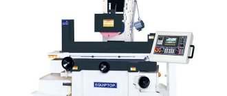
Centerless cylindrical grinding machine 3M182
| Parameter name | 3M182 | — |
| Main settings | ||
| The largest guaranteed diameter of the installed product, mm | 25 | |
| The largest permissible diameter of the installed product, mm | 35 | |
| Minimum diameter of the installed product, mm | 0.8 | |
| Smallest diameter recommended for plunge grinding | 2,5 | |
| Maximum length of processed products (limited by the rigidity and stability of the products) during through grinding, mm | 170 | |
| Maximum length of processed products (limited by the rigidity and stability of the products) during plunge-cut grinding, mm | 95 | |
| Height from the base of the machine to the axis of the circles, mm | 1060 | |
| Height from the bridge mirror to the axis of the circles, mm | 160 | |
| Grinding wheel | ||
| Maximum outer diameter, mm | 350 | |
| Smallest outer diameter, mm | 280 | |
| Maximum height, mm | 100 | |
| Hole diameter, mm | 203 | |
| RPM | 1910 | |
| Peripheral speed, m/sec | Up to 35 | |
| Leading Circle | ||
| Maximum outer diameter, mm | 250 | |
| Smallest outer diameter, mm | 200 | |
| Maximum height, mm | 100 | |
| Hole diameter, mm | 127 | |
| Maximum angle of inclination in the vertical plane, degrees | ±5 | |
| Maximum tilt angle in the horizontal plane, min | ±30 | |
| RPM during operation (stepless regulation) | 17—150 | |
| Number of revolutions per minute when straightening | 300 | |
| Grinding head | ||
| Grinding wheel spindle end size according to GOST 2323-67, mm | 80 | |
| Maximum installation movement, mm | 90 | |
| The greatest accelerated movement during plunge-cut grinding, mm | 20 | |
| Working movement per one division of the feed mechanism dial, mm | 0,001 | |
| Working movement per one revolution of the feed mechanism dial, mm | 0,08 | |
| Working movement of jog feed from the handle, mm | 0,001 | |
| Working displacement by plunge mechanism, mm | Up to 0.95 | |
| Feed rate during plunge-cut grinding is the highest, mm/min | 10 | |
| Feed rate for plunge-cut grinding is the lowest, mm/min | 0,06 | |
| Grandmother | ||
| Maximum displacement, mm | 80 | |
| Movement of the feed screw dial by one division, mm | 0,05 | |
| Movement of the feed rate dial per revolution, mm | 6 | |
| Wheel dressing mechanism | ||
| Transverse movement of diamond per dial division, mm | 0,01 | |
| Transverse movement of the diamond per one revolution of the dial, mm | 1,5 | |
| Maximum speed of diamond movement in the longitudinal direction, mm/min | 250 | |
| The speed of diamond movement in the longitudinal direction is the lowest, mm/min | 30 | |
| Maximum rotation angle of the copier, gra | ±2 | |
| Caliper | ||
| Maximum adjustment movement of the caliper knife in height, mm | 10 | |
| Hydraulic drive of the plunge mechanism | ||
| Pump capacity, l/min | 12/8 (double) | |
| Nominal pressure, kgf/cm2 | 10 | |
| Hydraulic tank capacity, l | 100 | |
| Lubrication unit | ||
| Capacity of the grinding wheel head spindle bearing lubrication pump, l/min | 5 | |
| Capacity of the spindle headstock bearing lubrication pump, l/min | 1,6 | |
| Grinding wheel bearing tank capacity, l | 65 | |
| Capacity of the drive wheel bearing tank, l | 15 | |
| Cooling unit | ||
| Pump capacity, l/min | 45 | |
| Magnetic separator throughput, l/min | 50 | |
| Capacity, tank, l | 120 | |
| Drive, dimensions and weight of the machine | ||
| Type of supply current | AC three-phase, current frequency 50Hz | |
| Supply voltage, V | 380 | |
| Electric drive voltage, V | 380 | |
| Control circuit voltage, V | 110 | |
| Voltage of local lighting circuits, V | 36 | |
| Signaling voltage, V | 5,5 | |
| DC voltage, V | 110 | |
| Grinding wheel drive motor - type | AO2-51-4-S1 | |
| Grinding wheel drive electric motor - power, kW, | 7,5 | |
| Grinding Wheel Drive Motor - RPM | 1460 | |
| Drive circle drive motor - type | PBST-22-V | |
| Drive circle drive electric motor - power, kW | 0,85 | |
| Drive Circle Drive Motor - RPM | 2200 | |
| Electric motor for driving an electric machine amplifier - type | EMU-12A-S1 | |
| Electric motor for driving an electric machine amplifier - power, kW | 1,2 | |
| Electric machine amplifier drive motor - rpm | 2900 | |
| Hydraulic pump drive electric motor - type | AOL2-21-4-S1 | |
| Hydraulic pump drive electric motor - power, kW | 1,1 | |
| Hydraulic pump drive motor - rpm | 1400 | |
| Grinding wheel spindle bearing lubrication pump drive motor - type | AOL21-4-S1 | |
| Electric motor drive of the grinding wheel spindle bearing lubrication pump - power, kW | 0,27 | |
| grinding wheel spindle bearing lubrication pump drive - rpm | 1400 | |
| Electric motor drive for lubrication pump of drive wheel spindle bearings - type | AOL11-4-S1 | |
| Electric motor driving the drive wheel spindle bearing lubrication pump - power, kW | 0,12 | |
| driving wheel spindle bearing lubrication pump drive - rpm | 1400 | |
| Cooling pump drive motor - type | PA-45-S1 | |
| Cooling pump drive electric motor - power, kW | 0,15 | |
| Coolant Pump Motor - RPM | 2800 | |
| Magnetic separator drive motor - type | AOL11-4-S1 | |
| Magnetic drive electric motor - power, kW | 0,12 | |
| Magnetic drive motor - rpm | 1400 | |
| Grinding wheel dressing drive electric motor - type | PL-062-S1 | |
| Grinding wheel dressing drive electric motor - power, kW | 0,09 | |
| Grinding wheel dressing drive motor - rpm | 1440 | |
| Drive wheel dressing drive electric motor - type | PL-062-S1 | |
| Drive wheel dressing drive electric motor - power, kW | 0,09 | |
| Drive Wheel Dressing Motor - RPM | 1440 | |
| Electric motor for driving rapid movement of the grinding headstock - type | AOL12-4-S1 | |
| Electric motor for driving the accelerated movement of the grinding head - power, kW | 0,18 | |
| Grinding headstock rapid movement motor - rpm | 1400 | |
| Total power of electric motors, kW | 11,67 | |
| Machine dimensions (length X width X height), mm | 2230 x 1455 x 2120 | |
| Weight of the machine with attached equipment, kg | 3470 |
Moscow, Mechanical Engineering. Encyclopedia 2002. Edited by K.V. Frolova
Types of centerless grinding
Currently, centerless external and internal grinding on rigid supports (shoes) is widely used in mass production. The Leningrad Association of Precision Machine Tools produces semi-automatic machines based on this principle, models LZ-191, LZ-193, LZ-190, LZ-192 for processing grooves of outer and inner rings of bearings. Moscow Automatic Lines Plant named after. On the occasion of the 50th anniversary of the USSR, a range of centerless grinding machines for processing bearing rings is being produced.
Centerless grinding of workpieces based on rigid supports is more effective than grinding of workpieces fixed in a chuck. This is due to the fact that the geometric shape of the workpiece when clamped in the chuck is distorted as a result of the appearance of significant deformations, the total processing error does not reach 5 microns. This disadvantage is eliminated when grinding holes on machines with rigid supports, the processing accuracy of which is ensured with deviations of less than 1 micron.
The design and layout of machines with workpieces mounted on rigid supports are characterized by a number of features.
The grinding wheel spindle is cantilevered, and the workpiece is driven using a magnetic chuck acting on its end.
The presence of rigid supports and the absence of a driving circle provide the following advantages: the accuracy of basing is increased by eliminating errors in the shape and runout of the driving circle; rigidity increases due to the absence of deformation of the drive wheel spindle assembly; The stability of the workpiece is increased as a result of its end being pressed against the chuck, as well as due to the possibility of adjusting the clamping force. The grinding wheel headstock is stationary relative to the frame, which significantly increases the rigidity and vibration resistance of the entire system. The allowance is removed by transverse feeding of the workpiece. Particularly important advantages of rigid support grinding are the simultaneous processing of several workpieces and the automation of the process of loading and unloading workpieces.
Centerless internal grinding can be carried out using drive, support and pressure rollers and on rigid supports. When grinding with rollers, there is no axial runout of the spindle. However, in this case, deformation of the workpiece due to the action of the pressure roller cannot be excluded. It is also possible that the runout of the drive and support rollers may have an impact on the machining accuracy.
The accuracy of hole machining depends on the correct geometric shape of the base outer surface of the workpiece, since errors in this surface are copied on the shape of the hole. With centerless internal grinding on rigid supports (Fig. 2), the workpiece is based on the outer surface, which, as a rule, has the shape of a cylinder, torus or cone. It rests freely on two radial rigid supports L and B. With its machined base end, the workpiece is pressed against the finished end of the rotating spindle faceplate either with the help of an electromagnet mounted in the faceplate, or with two rollers using springs. The presence of eccentricity e causes sliding between the rubbing surfaces; the larger e is, the more strongly the workpiece is pressed against the support.
Structurally, the supports are made as fixed point 1 or self-aligning 2 (Fig. 3). Self-aligning supports are recommended for processing workpieces with a diameter of more than 90 mm. Their use helps reduce scoring on the base surface of the workpiece.
For workpieces with a wide end surface, a grinding scheme with not only radial but also axial supports is currently used (Fig. 4). In this scheme, the rigid faceplate is replaced by a special electromagnetic driver 3, which presses the workpiece 1 to the axial supports 2. The rotation of the workpiece is transmitted through the driver connected to the spindle by a flexible drive 4. The workpiece is pressed against the radial supports by a separate electromagnetic device. With this grinding scheme, there is no spindle runout in the bearings and the processing accuracy increases.
The method of grinding holes on rigid supports is also used for workpieces with an unprocessed outer surface of any complex configuration. In this case, special intermediate devices (satellites) are used, in which the workpiece is pre-installed and secured, and then ground.
A new scheme of centerless grinding on rigid supports is widespread, eliminating axial runout of the spindle (Fig. 5). The workpiece is centered with the axis of the faceplate, which is a light guide not connected to the spindle. The workpiece is pressed against the radial supports by a special magnetic system 3. Rotation of the driver 1 is transmitted through an electromagnetic inductor 2 equipped with electromagnets or permanent magnets.
In recent years, a number of fundamentally new schemes for centerless grinding and, consequently, machine configurations for their implementation have appeared. At the Moscow Automatic Lines Plant named after. In honor of the 50th anniversary of the USSR, for grinding rods of large diameters and lengths (up to 20 m), a machine was manufactured with two driving wheels 1 and 3, made in the form of sets of disks, and one grinding wheel 2 located on top (Fig. 6). There is no support knife. This arrangement ensures reliable rotation of the heavy rod during the grinding process. Axial feed is carried out by turning the headstock of the driving circle in a horizontal plane at a certain angle.
In Fig. Figure 7 shows a schematic diagram of centerless grinding on machines (Schumach, Germany) with two grinding wheels 1 and 2 rotating towards each other. There is no drive circle, so to drive the workpiece, two pairs of rollers are used, located at the entrance and exit from the working area (not shown in the diagram). The workpiece is based on knife 3. This machine is designed for grinding rods of small diameter. By replacing one of the grinding wheels with an additional support knife, bars can be processed with increased precision.
Currently used centerless grinding machines with wide wheels (up to 80© mm in height) have a number of significant advantages over machines with narrow wheels. The main advantage is an increase in processing productivity by 2-3 times. During roughing operations, you can remove an allowance of up to 1 mm per diameter at a feed of 7-11 m/min. To obtain high accuracy, processing is carried out in two, less often in three passes. High-performance processing is carried out using the cutting-in method of multi-stage rollers.
In Fig. 8, a shows the layout of the machine with a fixed grinding wheel headstock 1 and a movable knife support 3 and a drive wheel headstock 2. The center line is horizontal. Machines of this arrangement are characterized by increased rigidity of the grinding wheel headstock. Adjustment of machines when the grinding wheel wears out or readjustment to another size is carried out by moving the support with the drive wheel, as well as corresponding movement and adjustment of loading and measuring devices. This is a disadvantage of this layout scheme. In Fig. 8, b shows the layout of the machine with a fixed knife support 2 and movable headstocks for grinding wheels 1 and driving wheels 3. The center line is horizontal.
Feeding to depth and compensating for wear of the grinding wheel is carried out by moving the headstock of this wheel. The headstock of the driving wheel is fed only when adjusted to the size of the workpiece being processed. This arrangement of working bodies is preferable for automating the processing process.
In Fig. Figure 9 shows the layout of the machine with a fixed grinding wheel headstock 1, a movable knife support 2 and a drive wheel headstock 3. The center line is slanted. The features of this layout are basically the same as the layout shown in Fig. 8, b.
In Fig. Figure 10 shows the layout of machines with movable heads of grinding wheel 1 and driving wheel 3 and a fixed knife support 2. The line of centers is inclined.
In Fig. 11 shows a layout with a fixed headstock 3 of the driving wheel and a knife 2 and a movable headstock 1 of the grinding wheel. The center line is vertical. A device 4 is provided to prevent the workpiece from falling out during processing. When the headstocks are positioned vertically, you can grind step or shaped workpieces by moving the knife support in the direction of the arrows. This excludes from the piece processing time the auxiliary time associated with installing the workpiece and removing the part, as well as with the supply and removal of the driving circle.
In Fig. Figure 12 shows the layout of the machine with two driving wheels 2 and 3 and a grinding wheel 1 located above the workpiece. In Fig. Figure 13 shows the layout of the machine, on which two grinding wheel heads 1 and 3 are movable, and the knife support 2 is stationary. Rotation and feeding of the workpiece are carried out by drive rollers 4 and 5.
In centerless grinding machines, in most cases, to carry out longitudinal feed of workpieces, the driving wheel is rotated through an angle a of up to 6° relative to the axes of the grinding wheel and the workpiece being processed. This ensures axial movement of the workpiece at the required speed. In the case of tilting the knife to perform longitudinal feed of the workpiece, a significant drawback of this processing scheme appears, associated with the need to straighten both circles to a complex profile (hyperboloid of rotation) for each diameter of the workpiece being processed.
Grinding metal surfaces
There is simply a huge number of different metal processing operations, all of which are characterized by the use of certain equipment and tooling. A common finishing process is the sanding process. It involves removing a small surface layer, due to which a certain roughness and more accurate dimensions are achieved. Let us consider the features of this process in more detail.
Metal grinding
The processing of metal and various alloys using an abrasive material is usually called grinding.
This technology allows you to change the roughness and other parameters of the outer or inner cylindrical, as well as flat surface.
Metal grinding can be carried out using various special equipment. When considering the features of such mechanical processing, you need to pay attention to the following points:
- The grinding process is the final stage of processing, which is carried out to obtain a certain roughness.
- This technology is not used to change sizes over a large range.
- Using modern equipment, the surface can be brought to the required roughness after heat treatment of the metal.
When carrying out the operation in question, a fairly large number of features are taken into account:
- Wheel speed is a parameter that depends on the outer diameter of the abrasive and the capabilities of the machine.
- Speed of movement of the part.
- Depth of cut.
- Possibility of cross feeding.
It is worth noting that today such technology is gradually being replaced by fine turning of metal at high speeds and minimal feed.
Main types of grinding
Grinding of parts can take place using a variety of technologies. The most widespread are the following:
- Circular grinding of metal.
- Changes in the roughness of internal surfaces.
- Gear grinding.
- Centerless technology.
- Sanding flat surfaces.
In addition, classification can be carried out according to the type of material used during processing. To automate the process and reduce labor costs, specialized machines are used. There are also models with a built-in CNC unit, which automates the process and ensures high quality of the resulting surface.
Centerless cylindrical grinding machines
In conditions of large-scale and mass production, it is advisable to use centerless cylindrical grinding machines. Based on the type of surfaces processed, these machines are divided into machines for external and internal grinding. External grinding can be carried out by three methods: “on pass”, “undercut” and “at point-blank range”.
In the first case, the workpiece 1
(Fig. 44) is located between the grinding wheel
2
and the driving
3
, resting on the support prism (knife)
4.
The grinding wheel rotates at high speed (30-60 m/s), and the driving wheel at a lower speed (0.2-1 m/s).
Since the coefficient of friction between wheel 3
and the workpiece is greater than between the workpiece and wheel
2
, the driving wheel rotates the workpiece at a circular feed speed
V
and the grinding wheel removes the allowance.
The longitudinal feed movement is achieved by rotating the drive wheel axis through an angle of a = 1.5¸6° for rough grinding and a = 0.5¸1.5° for finishing grinding. The peripheral speed Vs
of
the driving circle
3
is decomposed into two components:
V
and
S. The first is the rotation speed of the part (circular feed), the second is the longitudinal feed of the part. The larger the angle a, the greater the feed rate. To ensure linear contact of the driving circle with the cylindrical surface of the part, the circle is given the shape of a single-sex hyperboloid. The center of rotation of the workpiece is located above the center of circles 2
and
3
by 0.15-0.25 of the diameter of the part, which ensures the geometric accuracy of its shape.
Fig.44. Scheme of centerless grinding “on pass”
When grinding into “undercut” (Fig. 45, a
) part
3
, resting on the knife, only rotates.
Transverse feed is produced by moving the leading 2
or grinding
1
in a direction radial relative to the part.
By grinding “point-blank” (Fig. 45, b
) parts with collars or heads are processed.
The movements here are the same as during “pass” processing, however, moving in the axial direction, the part encounters a stop 5
.
After this, the driving wheel 2
moves away from the grinding wheel
1,
and the part is removed from the working area.
On machines for internal centerless grinding (Fig. 46) part 3
, being in contact with the support roller
1,
the pressure roller
2
and the drive wheel
5
, is processed by the grinding wheel
4.
Such machines are only suitable for processing parts whose outer surface has been pre-precisely machined.
Fig.45. Scheme of centerless grinding “undercut” and “stop”
Fig.46. Scheme of internal centerless grinding
Figure 47 shows a centerless cylindrical grinding machine. On the bed 1
2
is fixedly installed carrying a spindle with a grinding wheel
11.
On the right, in the longitudinal guides of the frame, there is a plate
8,
on which a headstock
6
with a rotating head
9
and a driving wheel
10.
The wheel can be rotated around the horizontal axis at the required angle.
A guide prism (knife) 4
, which serves as a support for the workpiece.
Setting the headstock 6
of the driving circle to the size of the workpiece, as well as compensation for wheel wear, is carried out by moving the headstock along the guides of the frame together with the plate
8
using the handwheel
7
and a screw drive.
The drive mechanisms are mounted inside the frame. The rotation of the circles is provided by an electric motor located on the left of the frame. Special devices are used for periodic dressing of the grinding and driving wheels with diamond pencils. 3
And
5
.
Fig.47. Centerless Cylindrical Grinding Machine
Internal grinding machines
Internal grinding machines are designed for grinding through and blind holes of cylindrical and conical shape, as well as for processing ends. These machines grind holes with a maximum diameter from 25 to 800 mm.
The machine is equipped with a face grinding device 4
, allowing you to grind the outer end of the product immediately after grinding its hole (Fig. 48).
Fig.48. Internal grinding machine layout
On the bed 1
There is a workpiece headstock
3
mounted on the bridge
2
, in the spindle chuck of which the part to be ground is clamped.
7
is installed on the longitudinal rolling guides of the frame .
On the transverse guides of the table there is a grinding head 6
, which carries a spindle with a grinding wheel. The hydraulic drive of the machine is mounted inside the frame. The machine controls are located on the front panel of the bed. The face grinding device is mounted on the headstock housing.
The main movement is carried out by an electric motor 8
through a flat belt drive. The grinding spindles are replaceable, which allows you to change the rotation speed of the grinding wheel.
Circular feed - rotation of the grinded part - is produced by a DC electric motor with stepless control of the shaft speed through a V-belt drive.
Longitudinal feed - reciprocating movement of the table - is carried out from a hydraulic drive with stepless speed control. The table also has a mechanism for manual longitudinal movement. In this case, rotation is transmitted from the flywheel through gears to the rack and pinion. The hydraulic and manual movements of the table are interlocked so that when the hydraulic drive is turned on, the manual feed is turned off by disengaging the rack wheel from the rack using a locking device.
The cross feed of the grinding wheel is carried out by moving the grinding headstock support slide with a screw from the cross feed mechanism. This feed can be manual (continuous or dosed) or automatic from a hydraulic drive.
The machines of the considered layout have two varieties. In the first case, the feed is carried out by transverse movement of the workpiece headstock, in the second - by movement of the grinding headstock.
The machines provide for dressing of grinding wheels, as well as compensation for wear of the main grinding wheel.
The most common universal devices used on internal grinding machines are self-centering chucks. The designs of jaw chucks with a spiral-rack mechanism for moving the jaws differ little from chucks of this type for lathes. In mass production conditions, high-speed membrane and magnetic cartridges are used.
Surface grinding machines
Surface grinding machines are designed for finishing surfaces on parts of various sizes. The main movement in these machines is the rotation of the grinding wheel. Depending on the shape of the table on which the workpiece is fixed, a distinction is made between longitudinal and circular feeding. When the width of the machined plane is greater than the width of the circle, the workpiece or circle is given a transverse feed. In addition, the grinding wheel or workpiece is subjected to periodic movement to a depth directed perpendicular to the plane being processed.
Grinding is carried out with the periphery or end of the grinding wheel. There are machines in which grinding is carried out simultaneously with the ends of two oppositely mounted wheels. When grinding with the end of a wheel, a distinction is made between grinding with a wheel whose axis is perpendicular to the plane being processed, and grinding with a wheel whose axis is inclined to the plane being ground.
Surface grinding machines with a rectangular table are made with horizontal and vertical spindles. Figure 49 shows the traditional layout of a surface grinding machine with a rectangular table and a horizontal spindle, working on the periphery of a wheel. On the bed 1
a column
2
, along the vertical guides of which the grinding headstock
3
. Along the horizontal rolling guides, slides
4
move (transverse feed movement), carrying longitudinal rolling guides along which the table
5
moves. The table moves from a hydraulic cylinder, the body of which is fixed to the slide
4
, and the piston rods are on the table
5
. The frame contains drives for the vertical movement of the grinding headstock and the transverse movement of the slide.
Fig.49. Kinematic diagram of a surface grinding machine with a rectangular table
Surface grinding machines with a round table also have a horizontal and vertical spindle arrangement.
In addition to general-purpose grinding machines, there are a large number of special machines designed to perform certain grinding operations on various workpieces of the same type. Among such machines, along with single-spindle machines, there are also multi-spindle machines, on which several grinding wheels are simultaneously installed, intended for external or internal grinding of rotating surfaces, for grinding flat and curved surfaces.
Depending on the shape of the surface to be ground and the purpose, the following types of specialized machines are distinguished: thread grinding, spline grinding, copy grinding, coordinate grinding, face grinding, sphere grinding, roll grinding (for grinding rolls of rolling mills), edge grinding, profile grinding, sharpening, various machines for auto- and tractor construction (for grinding crankshafts and camshafts, piston rings, etc.) and machines for grinding parts of rolling bearings.
Gear processing machines
With all the variety of machine tools and cutting tools used for cutting gears, there are two methods for manufacturing wheels: the method of copying the profile of the cutting tool and the rolling (bending) method, based on the mechanical reproduction of gearing.
Wheel cutting using the copying method is carried out by milling, planing, grinding and broaching. The tool cuts cavities between teeth on the workpiece, with the tooth profile matching the profile of the cutting tool. After processing each cavity, the workpiece is rotated by one tooth using a dividing head. This method has low productivity and processing accuracy. The tools can be a planing cutter (Fig. 50, a
), modular disk (Fig. 50,
b
) and finger (Fig. 50,
c
) cutters and a shaped grinding wheel (Fig. 50,
d
).
Fig.50. Schemes for the formation of a tooth profile using the copying method
The most widely used method in practice is the mechanical reproduction of gearing - the rolling method. It consists in the fact that the workpiece and the tool are given movements that reproduce the clutch of a pair of mating gear wheels or a wheel with a gear rack; At the same time, the cutting tool performs a working cutting movement. This method differs from the previous one in higher productivity and processing accuracy, and with one tool it is possible to cut wheels of a given module, regardless of the number of teeth.
Let's consider this method in a little more detail (Fig. 51). When moving a circle a
(or some curved line) in the plane, the latter occupies a number of successive positions
1
,
2
,
3
,
...
, depicted by dashed lines (Fig. 51,
a
).
Curves BB
and
CC
touching circle
a
in all its positions are called envelopes, and a moving circle
a
(or curve) is called envelope.
In Fig. 51, b
shows the formation of an involute curve
AB
, which is described by point
A
on the straight
line CC
, if this straight line is rolled without sliding in the direction of the arrow
k
along a stationary circle.
The segment DE
perpendicular to the line
AC
at point
A
will touch the involute curve in all positions of the line
CC.
This means that the involute curve in this case will be the envelope of a number of successive positions of the segment
DE
, moving along with the straight line
AC
and now being enveloped.
Fig.51. Scheme of formation of an involute curve
Thus, an envelope is a line (straight or curve) touching in all positions another straight or curved line moving in the plane, called the envelope. More precisely, the envelope is the geometric locus of the intersection points of infinitely close curves.
The concept of enveloping and bending lines forms the basis for the formation of an involute tooth profile by cutting. When gear cutting using the bending method, the profiles of the cutting edges of the tools, moving, occupy a number of successive positions relative to the profiles of the gear teeth, while cutting off the metal in those places where there should be cavities between the teeth. Involute profiles of the machined teeth arise in this case as envelopes of a number of indicated sequential positions of the cutting edges or, in other words, as envelopes of a series of successive metal cuts. Therefore, this method of profiling teeth is called the rounding or rolling method.
Figure 52 shows several examples of the formation of involute profiles of wheel teeth using the bending method. To reproduce the gearing of the wheel 1
and racks
2
(Fig. 52,
a
) it is necessary to carry out, firstly, the rolling of the wheel on the rack and, secondly, to impart to the cutting tool a reciprocating working cutting movement.
To obtain an involute tooth profile, it is necessary to ensure a certain ratio between rotation and translational movement of the wheel. So, when the wheel is turned by one tooth, during the same time it must move forward by the value of the tooth pitch. In Fig. 52, b
in the depressions of wheel
1
2
are shown , in relation to which the profiles of the wheel teeth are envelopes.
When cutting teeth with a hob cutter 3
(Fig. 52,
c
) the latter communicates the rotational cutting movement and the translational feed movement.
At the same time, the workpiece 1
is given a rotational movement, the direction of which depends on the direction of the cutter turn. If the cutter is right-handed, then the workpiece rotates counterclockwise, and if it is left-handed, it rotates clockwise. If you make an axial cut through a hob cutter, you will see that a row of cutting teeth on the cutter forms a rack. With each revolution of the cutter, this rack moves along its axis by the pitch of the hob cutter.
Fig.52. Examples of the formation of involute profiles
Considering the process of milling a wheel with a hob cutter, one can establish similarities with the process of processing a wheel with a cutting tool - a rack. Indeed, the conjugate rotation of the wheel and cutter results in a combination of wheel rotation and translational movement of the cutting rack. In Fig. 52, d
shows a number of positions of the cutting edges of the cutter teeth during processing. It is easy to see that the involute profiles of the wheel teeth are formed as enveloping rows of positions of the cutting edges of the cutter.
In the practice of cutting gears, the rounding method is widely used, in which the cutting tool is a cutter. 4
(Fig. 52,
d
), which is provided with reciprocating movement to ensure cutting and coordinated rotation with the workpiece
1
.
Figure 52, e
shows the sequential position of the teeth of the cutter
4
relative to the workpiece; in this case, the involute profile of the wheel tooth will be the envelope of all positions of the involute profile of the cutter tooth.
3 Gear-cutting machines are divided into various types according to the following criteria: a) by purpose - for cutting cylindrical wheels with straight and helical teeth, worm and chevron wheels, racks, bevel wheels with straight and curved teeth; b) type of working movement - gear hobbing, gear shaping, gear cutting and gear pulling; c) the nature of the processing - for cutting teeth and for finishing (finishing) teeth.
Gear shaping machines
Designed for cutting cylindrical wheels with straight and helical teeth of external and internal gearing, as well as herringbone gears. To cut them, gear cutters are used (Fig. 52, d
), gear-cutting combs (Fig. 52,
a
), the profiles of the working part of the cutters correspond to the profile of the depressions between the teeth of the wheel being cut. Gearing combs can only cut cylindrical wheels with external gearing.
The shaping part of the kinematic structure of gear shaping machines includes one or two shaping groups. Machines that use the rolling method to form a tooth profile have two shaping groups: simple and complex. A simple group is a cutting speed group that creates a reciprocating linear motion Ф V
(P1) of a cutter or comb when cutting straight teeth, or the reciprocating screw movement F
V
(P1B2) of a cutter (Fig. 53) when cutting helical teeth on wheels and oblique teeth on racks.
In both groups, the internal connection is provided by the connection of a kinematic pair: in group F V
(P1) - a translational pair of slider - straight guides of the machine rack;
for group F V
(P1V2) - a screw pair of sliders - screw guides for replaceable copiers.
The external connection of the F V
is provided by the kinematic chain
1
–
2
–
3
(Fig. 54) between the source of motion and the slider, including the
i V
and the crank mechanism.
A complex form-building group is the feed group, which creates a slow rolling movement Ф S
(В3В4) to form a tooth profile when rolling the cutter relative to the wheel being cut, or movement Ф
S
(П3В4) when rolling the cutter relative to the cutter rack, or the gear cutter relative to the wheel being cut.
The internal connection of group Ф S
(В3В4) is provided by one kinematic chain
4
–
5
–
6
with
the setting element
i
obk, and the external connection is provided by a chain
1
–
2
–
5
between the source of motion and one of the links of the internal chain with the setting element
i S. In gear shaping machines for cutting cylindrical wheels, there is a radial plunge group Вр(П5). The internal connection of this group is provided by the connection of the translational pair table carriage - bed guides (in some models of machines, the connection between the support and the cutter - transverse guides of the rack), and the external connection is carried out through chain 1
–
2
–
7
from the
M
through the cam to the table carriage (support with cutter) with the adjusting element
i
time.
Fig.53. Scheme of cutting helical teeth with a gear cutter
Wheels
Fig.54. Structural kinematic diagram of a gear shaping machine
In all gear shaping machines, in addition to the shaping process, a dividing process is also carried out, which is necessary for the uniform placement of cut teeth on the workpiece. However, most of these machines do not have independent dividing groups due to the fact that the dividing process is carried out simultaneously with the shaping process due to the multi-edge nature of the cutting tool and the closedness of the line on which the cutters and cutting teeth are located.
Kinematic tuning of gear shaping machines, like any other, comes down to tuning its chains. The structure of gear shaping machines contains only one complex group Ф S,
which has one internal kinematic chain with a tuning element
i
obk.
This chain in group Ф S
(В3В4) must provide the condition for kinematic coordination of the rotations of the cut wheel and the cutter of the following form:
,
and the internal chain in the group Ф S
(P3B4) must provide the condition for kinematic coordination of the movement of the cut (or gear-cutting) rack with the rotation of the cutter (or cut wheel) of the following type:
1 rpm (wheel) « p mz
dol (p
mz
zag) mm of rack movement,
where z
zag – number of cut wheel teeth;
z
dol – number of cutter teeth;
m
– modulus of cut teeth.
Movement setting Ф V
speed is carried out by a guitar
i V
M
is ensured with the reciprocating movement of the slider of the following type:
n M
min-1 of the electric motor rotor "
k
stroke/min of the slider,
where k
– the number of double strokes of the slider per minute.
The feed speed is calculated in millimeters of movement S
arc along the diameter of the initial circle of the cutter during one of its double strokes.
Adjustment to the feed speed is carried out through the feed guitar i S
, which should provide the following condition for matching the movements of the slider with the rotation of the cutter:
.
Gear hobbing machines
Designed for cutting cylindrical wheels with straight and helical teeth of external gearing using shaped disc wheels (Fig. 55, a
), finger (Fig. 55,
b
) and modular worm (Fig. 55,
c
) cutters.
If a gear milling machine has, in addition to a vertical lead screw, radial or tangential movement of the tool relative to the workpiece, then it can also cut worm wheels with hob cutters. A machine that has all three of the screws listed is classified as a universal gear hobbing machine. The profile of the teeth of wheels cut by milling is formed by the copying or rolling method, and the shape of the teeth along the length is formed by the touching method. Machines that use the copying method in combination with the touch method when cutting wheels with shaped disk or finger cutters have a simple structure, consisting of two simple groups Ф V
(В1) and Ф
S
(П2), as well as a group Д (В3).
The kinematic structure of gear hobbing machines is more complex, in which they use the rolling method when cutting wheels with hobs. The structure of such machines includes two or three shaping groups and does not have a separate division group. To form a tooth profile, a complex movement Ф V
(В1В2) is used, and to form a tooth shape along the length, the movement Ф
S
(П3) is used for a straight tooth, for a screw tooth Ф
S
(П3В4) and when milling a screw tooth with a diagonal feed - Ф
S
1(P3V4) and F
S
2(P5V6).
Fig.55. Shaping the teeth of cylindrical wheels using milling cutters:
A
– shaped disk;
b
– shaped finger;
c
– worm modular
The shaping of the teeth of the worm wheel is carried out using radial methods (Fig. 56, a
) and tangential (Fig. 56,
b
) incision.
The first method uses a radial displacement screw. The formation of the lateral surfaces of the teeth along the profile and length, as well as the dividing process, is carried out by one complex movement Ф V
(В1В2). The process of radial cutting of the cutter teeth into the workpiece is carried out by the movement Вр (П7).
The second method uses a tangential screw and a special hob cutter with a intake cone. The formation of the profile and shape of the tooth along the length, as well as the dividing process, is carried out, as in the first method, by the movement Ф V
(В1В2).
The second movement Ф S
2(П5В6) carries out tangential cutting due to the conical part of the cutter and once again the formation of the side surfaces of the cut teeth, therefore the second method is used for cutting more accurate worm wheels.
Fig.56. Formation of worm wheel teeth using cutting methods:
A
– radial;
b
– tangential
As can be seen from the above analysis, the most complex structure is that of a universal gear hobbing machine (Fig. 58), which has several private structures. The machine contains three complex shaping groups. The structure of each kinematic group consists of an internal connection in the form of an internal kinematic chain and an external connection through which the movement from the engine is transmitted to the internal connection. Internal circuit 1
–
2
–
3
–
4
groups of cutting movement Ф
V
(В1В2), called the rolling or profiling chain, as well as the dividing chain, connects the cutter spindle with the workpiece spindle (table) and through the guitar
i
obk provides the condition for kinematic coordination of the rotations of the cutter and the next workpiece type:
,
where k
– number of cutter passes;
z
– number of teeth of the cut wheel.
Movement speed Ф V
(B1B2) is configured using the tuning element
i V
, which is located in the external connection of group Ф
V.
Through the adjustment element
i V
, the condition for coordinating the rotations of the motor rotor
M
and the cutter spindle is ensured:
n M
min-1 electric motor
M
®
n
Fmin-1 cutter.
Fig.57. Kinematic structure of a universal gear hobbing machine
Internal circuit 5
–
6
–
7
–
8
–
9
–
3
–
4
feed movement groups Ф
S
1(П3В4), called a differential chain, connects through the differential the vertical lead screw nut, rigidly connected either to the table or to the cutter support, to the workpiece spindle and through guitar
i
differential provides the condition for kinematic coordination of the relative movement of the cutter along the axis of the workpiece with its rotation of the following form:
1 volume of blank " T"
mm relative movement of the cutter along
workpiece axes,
where T –
tooth helix pitch, ;
m
n – normal module; b – angle of inclination of the screw tooth.
Movement speed Ф S
1 (П3В4) is adjusted using the feed guitar
i S
, which is located in the feed chain
4
–
3
–
10
–
7
–
6
–
5
, connecting the nut of the vertical lead screw (table or cutter support) with the workpiece spindle, but not passing through the differential. The condition for coordinating the movements of the final links of the feed chain has the form
1 volume of blanks " S"
in mm relative movement of the cutter along
workpiece axes,
where S
c – feed per 1 rev.