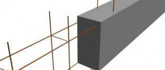
Reinforcing the corners of a strip foundation is necessary to strengthen the structure of the entire structure, eliminating the possibility of deformation and destruction of the structure under the influence of heavy loads and external negative factors. The corners and junctions of this type of foundation structure experience strong multidirectional loads, so work must be carried out in accordance with established norms and standards.
Otherwise, the entire structure may collapse, leading to delamination, spalling, and deformation. Provided the task is performed correctly, the reinforced concrete structure will be strong, able to withstand all loads, and will not be afraid of tensile and compressive forces.
Anchoring of reinforcement. Reinforcement connections. Bent rods
Requirements for anchoring and connecting reinforcement and bent rods are established in:
SP 52-101-2003 Concrete and reinforced concrete structures without prestressing reinforcement, clause 8.3.18-8.3.30
Manual for SP 52-101-2003 Manual for the design of concrete and reinforced concrete structures made of heavy concrete without prestressing reinforcement, clause 5.29-5.41 (2.02 MB; 3y ago; downloads: 4086)
GOST 14098-91 Welded connections of reinforcement and embedded products of reinforced concrete structures. Types, designs and sizes (the simplest is connection type S23-Re (47.5 kB; 3y ago; downloads: 4156))
For ease of work, a table has been developed in MS Excel (72.5 kB; 3y ago; downloads: 3024) to determine the relative (in diameters) and absolute (in mm) anchoring and overlap lengths for various cases
Docking points
A manual for the design of concrete and reinforced concrete structures made of heavy and light concrete without prestressing reinforcement (to SNiP 2.03.01-84):
clause 5.47 (5.37) It is not recommended to place overlapped joints of working reinforcement bars in the tensile zone of bending and eccentrically tensile elements in places where the reinforcement is fully used. Such joints are not allowed in linear elements whose cross-section is fully stretched.
Bent rods
It is necessary to distinguish between the minimum bending radii according to the conditions of reinforcement strength and the minimum bending radius according to the conditions of concrete strength at the bending point:
requirements for the bend radius according to the strength conditions of the reinforcement are established in clause 5.41 of the Manual (2.02 MB; 3y ago; downloads: 4086)
requirements for the bending radius according to the conditions of concrete strength at the bending point are established in clause 5.36 of the Manual (2.02 MB; 3y ago; downloads: 4086)
Application in the project
All connections of individual reinforcement bars are overlapped without welding. The overlap length of the reinforcement is at least 46 reinforcement diameters (when the number of working tensile reinforcement elements joined in one design section is no more than 50%) and at least 76 reinforcement diameters (when all working tensile reinforcement is joined in one design section of an element). Reinforcement joints fall into one design section if there are less than 60 diameters of the jointed reinforcement between their centers.
The lower reinforcement of floor slabs and coverings is not allowed to be joined in the middle third of the span. The upper reinforcement of the floor slabs and roofing must be joined in the middle third of the span.
The upper reinforcement of foundation slabs is not allowed to be joined in the middle third of the span. The lower reinforcement of the foundation slabs must be joined in the middle third of the span.
An increase in the consumption of reinforcement for overlapping bars 2) in the amount of: 4% for d8, 5% for d12, 6% for d16 is taken into account in the specifications for positions calculated in linear meters.
The minimum diameter of the mandrel for reinforcement is taken depending on the diameter of the rod:
the mandrel diameter is at least 5 rod diameters when the rod diameter is less than 20 mm;
the mandrel diameter is at least 8 rod diameters when the rod diameter is greater than or equal to 20 mm.
1) applicable for reinforcement class A500C and concrete class B30
2) is determined by the formula: Llap /11700, where Llap is the overlap length in mm
Armin. -02-04 15:04
Regarding overlapping rod joints without welding, the new regulatory literature (SP 52-101-2003, Manual for SP 52-101-2003, etc.) does not make any special mention, however, in the old manual there was a recommendation regarding joint locations.
A manual on the design of concrete and reinforced concrete structures made of heavy and light concrete without prestressing reinforcement (to SNiP 2.03.01-84) clause 5.47 (5.37). It is not recommended to place lap joints of working reinforcement bars in the tension zone of bending and eccentrically tensioned elements in places where the reinforcement is fully used. Such joints are not allowed in linear elements whose cross-section is fully stretched.
Accordingly, I write in the general instructions in addition to the indicated write (for floor slabs): The lower reinforcement of the slab is allowed to be joined, with the exception of zones in the middle third of the spans with a bypass ____. The upper reinforcement may be joined in the middle third of the span with a bypass _____.
For foundation slabs, the opposite is true.
Dmitry Rudenko. -02-04 15:11
Thank you, valuable note
How to make the right reinforcing frame
Proper reinforcement of important structural elements plays a very important role in ensuring the long life and performance of the entire structure. Therefore, you can do everything yourself only after carefully studying the parameters and standards, paying attention to each stage. Otherwise, it is better to leave the work to professionals.
Primary requirements:
- Reinforcement rods in the corners must be knitted while maintaining a distance between the rods of 50-80 centimeters.
- The distance between the longitudinal reinforcing belts is 50 centimeters, their number is calculated in each individual case.
- On both sides of each corner, 3-4 belts are installed transversely, with a step of 0.5 from the main one. Do the same in the corners.
- The diameter of the working reinforcement should be 1-2 centimeters, the diameter of additional rods can be 4-10 millimeters.
- Strict adherence to the sequence of work: first, vertical rods are driven into the ground, then horizontal rods are welded to the vertical rods at the top and bottom.
- It is advisable not to make joints in the corners, it is necessary to use bent rods, on straight sections of joints it is better not to make them at all, but if a joint is made, then only by the overlap method with the following parameters: 50 rod diameters for M200 concrete, 40 for M250, 35 for M300 . Vertical joining of longitudinal reinforcement is possible only with a spacing of at least 60 centimeters or 1.5 times the total overlap length.
- The main methods of joining materials: welding, overlap joining, using mechanical devices. Knitting of reinforcement at the corners of the strip foundation is carried out exclusively using special wire.
- To form a protective concrete layer at least 5 centimeters thick after pouring, special devices are used - “frogs” or “chairs” are installed on the bottom, and “stars” on the sides.
Correct calculation
To anchor reinforcement in concrete slabs, you need to take into account all construction nuances. The calculation of the operation of sealing steel products is mastered by studying the following indicators:
- Maximum strength of reinforced concrete.
- Indicator of tension on the clutch area.
- A type of anchorage.
- Profile of the reinforcement used.
- Depth and length of laying steel parts.
- Section of rods.
A simplified method for calculating important indicators (length, depth) allows craftsmen to carry out all construction work with high quality in the shortest possible time. For these purposes, you can use a special table that includes various indicators. You can study all the necessary data using a computer program. If you enter all the data, you can ultimately get a comprehensive anchorage calculation.
Incorrect corner reinforcement
Reinforcing the corners of a strip foundation is a complex task, so it is not surprising that in the process craftsmen make mistakes, which, as a rule, are similar. Errors in calculations and savings on the materials used, attempts to make everything simpler and faster usually result in big problems - at least the appearance of deformations and cracks, and at maximum - the destruction of the building.
Bending theory
Home Catalog Tools and consumables Tools for press brakes
BENDING TO CONTACT AND TOOLING BENDING.
Bending to Contact: After selecting the desired V-channel, place material on both edges of the V-channel. After setting the stroke step, the upper tool will begin to move, bending will be carried out to the required value (30, 60, 75, etc.)
Please note that the material will experience stress during the bending process. Important values when choosing a V channel: - Sheets up to 3 mm - 6-8 x S - Sheets over 3 mm - 8-12 x SS - thickness of the bending sheet
Note: These values are also taken into account when bending short material. The resistance values, internal radius and other information required for the bending table are in the Instructions. Example: Sheet thickness 3 mm, required channel width 25 mm, bending sheet 18 mm. The internal radius is 4.2 mm and the required resistance is 21 tons. Be attentive to the following points when bending: A – 3 points for effective bending. These are both edges of the lower tool and the bending edge of the upper tool. B – Bending sheet (90) with mechanical processing. The upper tool must be pressurized on both sides until it reaches the channel of the lower tool. The advantages of this process are as follows: 1 – There is no need to use all the tonnage resistance of the Press. 2 – Possibility for bending sheets of appropriate thickness. 3 – The same tool can be used at different bending levels. The following tolerances must be taken into account when bending the materials of the old shape, inclined backwards until they touch: a - bending with a pointed tool +/- 2 b - bending with a standard tool +/- 3 c - bending with a blunt tool +/- 5 Difference in levels of total length and bending thickness before contact: Example: 2 mm sheet thickness with 140 bends. Selected opening of channel V: V: 8 x s: 8 x 2: 16 mm As can be seen from the following table, if we take as a basis that the difference in the thickness of the total length of the material is 10%, then this means that the difference in level will be 2.5 . The values given are calculated theoretically and in practice as described above. ACCORDING TO DEHLER TABLE
PRESSING USING A TOOL.
To achieve good results on precise profiles, the tools must be of very good quality. In this situation, high tonnage is required. The pressing level on these machines is already set, so there is no need to make any settings yourself. Advantages: Since the tendency of the material to return to its previous shape is minimized, the difference in levels will be minimal. Disadvantages: high tonnage and high bending require expensive tools.
The bending of the sheet is related to the value of the radius V of the channel and is not related to the thickness of the sheet and length. Under such conditions, the radius is less than the radius V of the channel.
As you know, metal sheets tend to return to their original shape due to the elasticity of the material. This is due to the following: A – proportions required by the standard B – Material intensity C – Material coating C – Contents
P: Pressure resistance (ton) L: Sheet length (mm) R: Resistance (kg/mm2) s: Sheet thickness (mm) V: Channel distance Example: Sheet length: 1000 mm Resistance: 42 kg/mm2 If channel width V : 8 x S is selected, then the following value is obtained.
With this formula, there is no need to perform the remaining calculations to find the pressure resistance (tonnage). Length: 2500 mm Sheet thickness: 2 mm Resistance: 45 kg/mm2 Suitable pressure resistance 2.5 x 8 x 2: 40 tons, as the last example shows, a material stiffness of 40-45 kg/mm2 requires a resistance of 2.5 mm . If the press brake is used beyond its capabilities, it may cause damage to the tool and material. When a sheet bends with a resistance of more than 40 kg/mm2, in this case, as practice shows, 10% must be added to the obtained value. On hard material this value is 10-12 x S and due to the rigidity of the material the possibility of damage is prevented.
135 – Angle difference that can occur due to V-channel opening.
BENDING DIAGRAM
Capacity (tons) L: - Sheet length (mm) (L=1000mm) R: - Outer radius (mm) Tensile strength (kg/mm2) V: - Template distance P: - Required tonnage (tons) N: - Minimum bending sheet length (mm) S: — Sheet thickness (mm)
IMPORTANT INFORMATION FOR BENDING.
Figure 1: The figure shows the maximum tonnage allowed for determining the bending length. TS: - Total sheet length. Figure 2: - When you need to make short bends, as shown in Figure 2, you should bend the material to the same length at both ends of the machine.
Why do you need to reinforce a strip foundation?
The need to reinforce a strip foundation on ordinary soil or on loam in the corners is explained by the properties of building materials. Concrete itself is not flexible and strong enough to easily withstand tension and other loads operating in different parts of the foundation, especially when it comes to uneven loads (caused by soil heaving, temperature changes, moisture, etc.).
During deformation, zones of tension and compression appear in a concrete structure. And while concrete can survive compression, tension destroys it. In order to counteract this load, reinforcement is needed: a metal frame is placed inside the concrete structure, which absorbs tensile loads and significantly strengthens the material, extending the life of the entire structure.
The angle of the tape and the junction points are the most important points of the structure; greater pressure is exerted on them compared to the longitudinal parts, so special attention should be paid to their strengthening.
Clause 3.71. About the pitch of transverse reinforcement.
Once you have determined the diameter of the clamps, you need to assign their pitch. Calculation is by calculation, but finally we always check Table 25. As you can see, the pitch of the clamps depends on the class of reinforcement, this must be taken into account when choosing. The Rac value is the calculated compression resistance of the reinforcement for the limit states of the first group.
With a reinforcement percentage μ of more than 3%, you also need to be careful - it immediately causes a thickening of the transverse reinforcement spacing. Moreover, when joining reinforcement in an overlap, with a reinforcement percentage of 3 or more, problems always arise with the placement of reinforcement. Such saturated reinforcement should be avoided whenever possible.
Please note that if you overlap the reinforcement, there is always a more frequent arrangement of clamps in the overlap areas.
If you use reinforcement according to DSTU 3760, check all the requirements also according to the “Recommendations for the use of rolled reinforcing bars according to DSTU 3760-98” and choose the worst option.
Direct anchoring.
Direct anchoring of reinforcement is arranged in places where the geometry of the structure allows this, and can sometimes be located in a protective layer of concrete. Direct anchoring is allowed only for periodic profile reinforcement.
The presence of additional compression of concrete from external force factors in the anchoring zone increases the bearing capacity of the concrete itself, thereby increasing the effectiveness of anchoring (adhesion).
When directly anchored in a concrete protective layer, the longitudinal force tries to chip away at the protective layer through shear stresses.
Rice. 1. Possibility of chipping the protective layer of concrete during anchoring.
Our standards do not stipulate the length of anchorage depending on the location of the rod in the structure, therefore anchoring in the protective layer of concrete is not recommended without the presence of transverse reinforcement or some other additional measures (increased anchorage length, installation of upper perpendicular longitudinal or transverse reinforcement, increase in the protective layer , bending device, etc.), with the help of which shear stresses will be perceived and chipping of the protective layer of concrete will be excluded.
Installing perpendicular longitudinal reinforcement along the top in the anchoring zone increases the chipping area of the protective layer of concrete, but its use is less effective than installing transverse reinforcement.
The pitch and diameter of the clamps in the area of direct anchoring in the protective layer of concrete is determined depending on the type of clamp and the diameter of the longitudinal reinforcement.
The estimated length of direct anchorage of reinforcement in concrete is determined
(SP 52-101-2003 clause 8.3.22 or SP 63.13330.2012 clause 10.3.25):
For elements made of fine-grained concrete of group A, the required design anchorage length must be increased by 10ds for tensile concrete and by 5ds for compressed concrete.
It is allowed to reduce the length of direct anchorage of non-prestressing reinforcement bars depending on the number and diameter of transverse reinforcement in the anchoring zone, the type of additional anchoring devices (welding of transverse reinforcement) and the amount of transverse compression of concrete in the anchoring zone (for example, from the support reaction), but not more than thirty%.
In any case, the actual anchoring length is taken to be no less than 15ds and 200 mm, and also no less than 0.3×lo,an.
Design length of direct anchorage of tensile (non-prestressed) reinforcement at k=1 class A400:
| Concrete compression class | Lan/ds | Anchoring length (mm) depending on the diameter of the reinforcement | |||||||||||
| 6 | 8 | 10 | 12 | 14 | 16 | 18 | 20 | 22 | 25 | 28 | 32 | ||
| B15 | 47,32 | 284 | 379 | 473 | 568 | 663 | 757 | 852 | 947 | 1041 | 1183 | 1325 | 1515 |
| IN 20 | 39,41 | 237 | 315 | 394 | 473 | 552 | 631 | 710 | 788 | 867 | 985 | 1104 | 1262 |
| B25 | 33,77 | 203 | 270 | 338 | 405 | 473 | 540 | 608 | 676 | 743 | 844 | 946 | 1081 |
| B30 | 30,84 | 200 | 247 | 309 | 370 | 432 | 494 | 555 | 617 | 679 | 771 | 864 | 987 |
| B35 | 27,28 | 200 | 218 | 273 | 328 | 382 | 437 | 491 | 546 | 600 | 682 | 764 | 873 |
Design length of direct anchorage of tensile (non-prestressed) reinforcement at k=1 class A500:
| Concrete compression class | Lan/ds | Anchoring length (mm) depending on the diameter of the reinforcement | |||||||||||
| 6 | 8 | 10 | 12 | 14 | 16 | 18 | 20 | 22 | 25 | 28 | 32 | ||
| B15 | 58 | 348 | 464 | 580 | 696 | 812 | 928 | 1044 | 1160 | 1276 | 1450 | 1624 | 1856 |
| IN 20 | 48,32 | 290 | 387 | 483 | 580 | 677 | 773 | 870 | 967 | 1063 | 1208 | 1353 | 1546 |
| B25 | 41,41 | 249 | 332 | 414 | 497 | 580 | 663 | 746 | 828 | 911 | 1035 | 1160 | 1325 |
| B30 | 37,81 | 227 | 303 | 378 | 454 | 530 | 605 | 681 | 756 | 832 | 945 | 1059 | 1210 |
| B35 | 33,44 | 201 | 268 | 335 | 401 | 468 | 535 | 602 | 669 | 736 | 836 | 937 | 1070 |
Design length of direct anchorage of tensile (non-prestressed) reinforcement at k=1 class A500SP with an effective profile:
| Concrete compression class | Lan/ds | Anchoring length (mm) depending on the diameter of the reinforcement | ||||||||||
| 6 | 8 | 10 | 12 | 14 | 16 | 18 | 20 | 22 | 25 | 28 | ||
| B15 | 53,56 | 322 | 429 | 536 | 643 | 750 | 857 | 964 | 1071 | 1179 | 1339 | 1500 |
| IN 20 | 44,63 | 268 | 357 | 446 | 536 | 625 | 714 | 804 | 893 | 982 | 1116 | 1250 |
| B25 | 38,25 | 230 | 306 | 383 | 459 | 536 | 612 | 689 | 765 | 842 | 956 | 1071 |
| B30 | 34,94 | 210 | 280 | 350 | 419 | 489 | 559 | 629 | 699 | 769 | 874 | 979 |
| B35 | 30,91 | 200 | 247 | 309 | 371 | 433 | 495 | 557 | 618 | 680 | 773 | 866 |
Note: the ratio in the tables Lаn/ds for non-prestressed reinforcement with a diameter greater than 32 mm must be divided by a factor of 0.9.
Technology
The number of bends and the distance between them are determined taking into account the individual characteristics of each specific order. Namely, the requirements for arc smoothness. The number of bends is directly proportional to the smoothness. The more there are and the smaller the step between them, the smoother the bend at the exit.
We perform processing on universal specialized equipment designed for plastic deformation. Radial bending is performed taking into account the characteristics of the metal and customer requirements. We create products of any complexity that fully comply with technical specifications.
Types of beams
What is a reinforced concrete beam structure? What are the differences in installation method and section shape?
A beam is an element made of concrete and reinforced with steel rods that works as part of a building structure and absorbs force loads. Such building structures are also called crossbars or purlins. Depending on the installation method, they can be:
- Monolithic elements, which are single-span structures freely located or clamped on one or both sides.
- Combined (prefabricated-monolithic) structures, including cantilever ones.
- Prefabricated, consisting of individual parts that are part of an overall multi-span structure.
The cross-section of the elements is different and can be rectangular, trapezoid, T-beam, I-beam or other types. According to building codes, the section width is taken to be 5 centimeters and is a digital series, starting from 100 mm and ending with 250 mm. The height of the product changes accordingly.
The combination of reinforcing bars and concrete gives a combination of their properties
Do-it-yourself manual reinforcement bender. Drawing, description
In order to make a simple reinforcement bender you will need:
- steel base, which can be used as a part of a steel sheet with a thickness of at least 6 mm;
- steel angle with dimensions from 40×40×2 and a length of at least 4...5 times the length of the largest horizontal dimension of the reinforcing bar - rotary lever (the longer the lever, the lower the bending force);
- a rolling bearing unit in which the drive arm will rotate;
- reinstallable stops - steel angles fixed in the drive lever;
- guides - bushings made of tool steel type U8, freely rotating on their axis. To properly guide the workpiece along the base, there should be two of them, but for the simplest work one is enough. It is better to harden the bushing to HRC 50…55;
- wooden handle mounted on a lever.
Installation of such a bender is simple and does not require the use of welding equipment. The base is securely fixed to the workbench, after which the desired size of the corner is selected - a blank for the swing arm. Grooves are milled or drilled into it for installing stops, the locations of which correspond to the dimensions of the required reinforcement (however, a through groove can also be provided). The bearing and guide bushings are attached to the desired location on the base.
Using such a device, you can perform horizontal and vertical bends at arbitrary angles. To increase accuracy, you can provide a manual reinforcement bender with a dimensional scale.
Reinforcement options
The correct scheme for reinforcing corners requires mandatory anchoring, the formation of connections of different strengths for different zones of the wall. After all, corners and junctions are constantly subjected to severe loads and must be as rigid as possible.
You cannot simply knit the longitudinal rods directly; this will not provide adequate structural strength. There are three methods of reinforcement of this type.
Basic reinforcement methods:
U-shaped installation
Special U-shaped elements are used at the corners and junction points. The width of the element is equal to the width of the frame, the length is at least 50 diameters of the longitudinal rod. The elements are tied to the main longitudinal rods with the open part of the P side in the direction of the corner, in each of which two elements are installed (for each horizontal level). At junction points, one per level is sufficient.
Claw and lap joints
Rigidity is ensured by bending the free end; the internal reinforcement is overlapped with the horizontal reinforcement, and knitted with a paw to the external ligament. The pitch of transverse corner and vertical reinforcement is calculated in the ratio of 3/8 of the height of the foundation. The length of the paw should be 3-5 centimeters.
Using an L-shaped clamp
The internal longitudinal bars are rigidly attached to the external longitudinal bars with an overlap, the pitch is ¾ of the height of the foundation, the external and internal longitudinal frames are connected by additional transverse elements. The length of the overlap joint is equal to 50 diameters of the horizontal rods.
How to bend reinforcement without machines
If there is no special equipment and it is not possible to build the device on your own, you can resort to the manual bending method. But such an event is quite traumatic. However, it must be taken into account that the manual method is suitable for bending rods up to 8 mm. In addition, the quality of such metalworking will not be the highest. Using rods bent in this way, it will not be possible to create a reliable, durable and load-resistant foundation.
To process fittings of larger diameter, you can use 2 pipes. The principle of the procedure: a steel bar is fastened in one pipe, and the second is put on the protruding end of the rolled product and is used as a lever. Metal rods of small diameter can be bent directly from the ground by simply standing on a support pipe (with your own weight).
There is another option, which involves fastening the fixing pipe, for example, in a vice or using concrete in a place specially created for this. There is another way: pins are driven into the ground, which will serve as stops. The material is placed between the pins, and the pipes act as a lever.
It is not recommended to bend steel reinforcement yourself when it comes to organizing a foundation or preparing material for other important work. In these cases, special equipment must be used. Only in this case will you receive reliable reinforcement that can withstand quite serious loads. You should not save on metalworking, since not only the durability of the structure being built depends on it, but also the safety of people.
Our company sells fittings of all popular diameters. We offer competitive prices and deliver products. You can also use our steel bending service. We process rods with a diameter of up to 40 mm. We guarantee high precision bending according to the specified parameters. For more information, contact our managers.
Correct reinforcement of the corners of a shallow strip foundation
- The frame is placed at a distance of 5 centimeters from the foundation.
- Connections are made using reinforcement bent at 90 degrees, without welding. Fasten on straight sections with wire.
- Be sure to lay a cushion of sand and gravel at the bottom of the trench, which will ensure sufficient strength of the base.
The maximum stress is usually concentrated in the corner and different layers of the frame experience different loads. And the main task of the reinforcement is to make sure that the steel rods absorb these loads evenly, completely taking them over themselves. And if the metal rods are connected incorrectly or with breaks, then the foundation will simply turn into a set of parts, each of which by itself will not give any benefit, and the concrete will quickly delaminate and become covered with chips and cracks.
Therefore, all work must be performed correctly, avoiding simple crosses of the ends of the rods in the indicated places, as can often be found in construction practice.
Reinforcement bending at METAL BUREAU
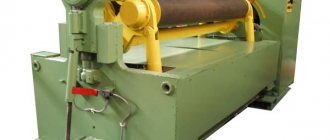
The technological process of bending building reinforcement and its types in METAL BUREAU
A flexible reinforcing workpiece or part thereof is given a curved, curvilinear shape. This technological operation is also used for straightening reinforcement. When a reinforcing bar is shaped, the outer layer of metal is stretched and the inner layer is compressed.
To bend reinforcement, depending on the volume and technical requirements of the order, METAL BURO uses the following methods:
- manual
- mechanized
Use of bent reinforcement from METAL BURO in construction
To reinforce reinforced concrete, monolithic structures, you may need not only straight reinforcing bars, but also bent reinforcement (clamps, brackets, hooks, etc.), for example:
- At the end sections of the walls of buildings along their height, transverse reinforcement is installed in the form of U-shaped/closed clamps, which create anchorage of the end sections of horizontal rods and help protect the end compressed vertical reinforcing rods of the walls from buckling.
- When designing joints between beams and columns, transverse bent reinforcement is used in the form of closed clamps/U-shaped parts, which are placed in the area of the working reinforcement of the beam.
Methods for manual bending of reinforcement in METAL BUREAU
Bending of light reinforcement can be done manually:
- bending of reinforcing bars with a diameter of up to 6 mm, fixedly fixed, is carried out using hammers and round-nose pliers
- for bending reinforcement 12 - 14 mm (or less), you can use a manual machine
- reinforcement 14 mm or more can be straightened and bent manually using correct plates with fixed corners/with several pins attached and special keys included with the plates; the dimensions of the key are selected in accordance with the diameter of the reinforcing bar
The operating principle of a manual machine for bending reinforcement in METAL BUREAU
The manual bending machine is designed for cold bending of reinforcement. A plate is installed on the machine body, on which there is a working disk with a central and bending fingers, which rotate together with it to the right or left using a long lever handle. A thrust pin located next to the disk is attached to a stationary frame. The bending of the reinforcing bars occurs around the central pin (the bending radius is determined by its diameter), the thrust pin helps to keep the rod from turning.
The rotating disk allows for the use of interchangeable fingers of different diameters to adjust the radius/angle of bending. The use of a manual machine is justified for small volumes of construction for the manufacture of reinforcement products of low precision. The process of bending a rod manually is labor-intensive and lengthy, so for large volumes of reinforcement, mechanized equipment is used.
Mandrel for mechanized bending of reinforcing bars in METAL BURO
Modern methods of bending reinforcement are based on the use of mechanized equipment, which has high productivity and allows simultaneous bending of several rods tucked into a special holder, accurately providing the required parameters of bent products that affect the reliability of reinforced concrete and monolithic structures.
Thus, in monolithic construction, the use of bent reinforcement with bends/bends of rods requires compliance with certain bending diameters of the rods, which are necessary in order to prevent splitting/destruction of concrete inside the bend of the reinforcing bar. Therefore, when bending rods, the diameter of the mandrel is selected depending on the diameter of the reinforcement, for example:
- for smooth reinforcement with a diameter of up to 20 mm, the mandrel diameter is chosen to be at least 2.5 x the diameter of the reinforcement/at least 4 x the diameter of the reinforcing bar, respectively
- for periodic profile reinforcement with a diameter of up to 20mm / 20mm, the mandrel diameter will be equal to at least 5x the diameter of the reinforcement / 4x the diameter of the reinforcement, respectively
For thermomechanical fittings A500C. A500SP bending is carried out only in a cold state. Reinforcement bending is carried out with a maximum bending angle of 180˚.
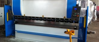
For bending reinforcement METAL BURO uses machines with electric/hydraulic drive, as well as automated machines with program control, which make it possible to obtain high-precision reinforcement products with a given bending radius. The machines have different capacities and are designed for bending light (up to 14 mm in diameter) and heavy reinforcement with a diameter of 14 mm, incl. reinforcement for large reinforced concrete structures.
How to properly reinforce corners
First, frame drawings are made, where the main values are written down, important parameters and indicators are calculated, and the required minimum reinforcement in the calculation is determined. Then they implement the task.
Reinforcement scheme:
- Fix the vertical rods at intervals of 60 centimeters.
- Using knitting wire, fasten the horizontal power rods at the top and bottom of the contour at the places where they intersect.
- Strengthen the areas located in the middle of the spans with additional rods.
Errors when tying reinforcement at corners:
- The reinforcement is simply crossed in the corners, secured with wire. This is wrong, although the scheme is quite common.
- In the corners the rods are bent, but not anchored. Thus, SP 50-101-2004 says that prefabricated monolithic and monolithic foundations must be rigidly connected by cross strips. A connection with a regular crosshair means a break at the bend, which will not provide sufficient rigidity. In places where they overlap, the rods can be connected only in the indicated ways: mechanically with couplings, welding, without welding (overlapping corrugated rods with straight ends, with transverse or welded rods, with bends at the ends).
- Using only one strapping circuit.
- Using two circuits without properly securing them together.
- Lack of structural connection between the reinforcement frame and the base.
- In the corners of the structure, the rods were connected by welding, ignoring other joining methods.
How to knit reinforcement correctly
Knitting of reinforcement in the corners of the strip foundation is carried out using the following means: grinder, rods, gas or electric welding machine. First, everything is calculated - the number of rods, their diameter, and knitting methods depend on the calculation. Particular attention is paid to strengthening the sole, making the structure on site.
Two contours are welded, one with an indentation of 5 centimeters from the outer perimeter of the foundation trench. The second is placed at the same distance from the inner edge. The weld seams should not be in the corners. The reinforcement is bent at right angles, the bending points are heated, welding is used only where the loads are relatively low.
Next, the structure is lowered into the trench, and vertical rods are installed in the corners. The pins are driven deep into the ground, the contours are welded to the vertical posts. The upper part of the foundation should also be made of two contours.
Before tying reinforcement, it is necessary to study the types of tying. Simple connections are not suitable in this case. It is imperative to use bent elements that will continue the longitudinal rods of the frame and protrude beyond the corner by 60-70 centimeters. If the length of the rod is not enough, you can fasten it with clamps with sides equal to at least 50 diameters of the reinforcement used.
Useful tips for correct installation of reinforcement
- The distance between vertical rods up to 20 millimeters should be equal to 50-80 centimeters.
- You need to use working steel rods with a diameter of 1-2 centimeters, additional elements must have a cross-section of at least 4-10 millimeters.
- It is advisable to use non-metal pads that will fix the frame at the required distance from the ground and nearby structures.
- Horizontally located rods are mounted exclusively in a bent form.
- You cannot connect end to end.
Sheet metal bending radii
When deforming workpieces, it is important to know the minimum bending radii of sheet metal. For each element or alloy these indicators are different
If you do not take them into account, the workpiece can easily be damaged.
In addition to the material, the bending radius is affected by:
- type of sheets (annealed, riveted);
- position of the bend line (along or across the fibers).
Minimum bending radius of sheet metal
For example, consider the minimum metal bending radii in the table.
| Material | Annealed | Riveted | ||
| Fold line | ||||
| Across the grain | Along the fibers | Across the grain | Along the fibers | |
| Aluminum | 0,2 | 0,3 | 0,8 | |
| Copper | 0,2 | 1 | 2 | |
| Brass L68 | 0,2 | 0,4 | 0,8 | |
| Soft duralumin | 1 | 1,5 | 1,5 | 2,5 |
| Solid duralumin | 2 | 3 | 3 | 4 |
| Steel 05–08 | 0,2 | 0,2 | 0,5 | |
| Steel 8–10, St1 and St2 | 0,4 | 0,4 | 0,8 | |
| Steel 15–20, St3 | 0,1 | 0,5 | 0,5 | 1 |
| Steel 25–30, St4 | 0,2 | 0,6 | 0,6 | 1,2 |
| Steel 35–40, St5 | 0,3 | 0,8 | 0,8 | 1,5 |
| Steel 45–50, St6 | 0,5 | 1 | 1 | 1,7 |
| Stainless steel Х18Н9Т | 1 | 2 | 3 | 4 |
Maximum bending radius of sheet metal
There is no concept of a maximum bending radius. If a specialist knows exactly what the minimum bending radius of sheet metal is, then any larger options are suitable.
Calculation of sheet metal bending radius
From what was written above, it follows that the calculation of the bending radius of sheet metal is based on its parameters. The material of manufacture, the thickness of the product, the method of manufacturing the workpiece, as well as the wishes of the customer are taken into account. The latter directly depend on what product you need to receive.