Characteristics of extraction operations
Drawing is the process of turning a flat or hollow workpiece into an open-top hollow product, carried out using drawing dies. Based on the shape and technological features of sheet stamping, hollow parts produced by drawing can be divided into several main groups:
1) parts having the shape of a body of revolution;
2) box-shaped parts;
Rice. 1. Hollow parts of various shapes (a-l), obtained by drawing
Parts that have the shape of a body of revolution can be with or without a flange, with a flat or shaped bottom (Fig. 1, a-e).
Box-shaped parts can have square, rectangular, curved side walls with or without a flange; their bottom can be flat or shaped (Fig. 1, f-h).
Parts of complex shape can be semi-symmetrical, having only one plane of symmetry (the body and roof of the car cabin, Fig. 1, i), and asymmetrical (the wing of the car, Fig. 1, j).
Depending on the shape of the part, the workpiece is either drawn in its pure form or drawn in combination with forming, bending and crimping, or flanging.
Extraction is carried out on double- and triple-acting crank presses, double-acting rocker presses with a movable lower table, single-acting (single-stroke) crank presses with a pneumatic or hydropneumatic device (cushion), as well as on single- and double-acting hydraulic presses.
Rice. 2. Scheme of the drawing process: d1 - diameter of the hollow workpiece after
first operation; d2 - diameter of the hollow workpiece after the second operation
A special group consists of wrapping operations—the production of hollow parts of a curved shape by stretching the material and wrapping it around a special wrapping template—a block (Fig. 1, l). The wrapping is done on special wrapping hydraulic presses.
According to the nature and degree of deformation, they distinguish: 1) drawing without thinning the walls; 2) a hood with thinning walls (broach) and 3) a combined hood.
In the first case, drawing occurs without a predetermined change in the thickness of the product wall material, but with a significant reduction in the diameter of the workpiece; in the second, drawing is carried out due to a predetermined reduction in the wall thickness of the drawn semi-finished product with a slight decrease in its diameter. Combined drawing is characterized by a simultaneous significant reduction in the diameter and wall thickness of the drawn semi-finished product.
Depending on the relative thickness of the workpiece or semi-finished product, drawing is carried out with or without the use of a clamp. Since during drawing the material of the workpiece 3 is drawn in by a punch 2 with a rounding rп of a larger diameter D into a matrix 1 with a rounding rm having a smaller diameter d (Fig. 2, a), it is natural that folds (corrugations) form along the edge of the elongated cap due to the presence of excess material or the so-called characteristic triangles b, b1, b2, . bn (Fig. 2, b), because to form a hollow cap with a diameter d and a height h, it would be enough to have a workpiece with a diameter D' without shaded areas. The presence of excess triangles leads to the need to displace and move the metal when drawing upward. In Fig. 2, c shows the drawing in the second operation from a hollow workpiece 4.
Rice. 3. Hood with material pressing
The formation of folds is caused by the stress-strain state of the metal, which, under certain geometric relationships, leads to loss of stability of the workpiece (Fig. 2, a).
To prevent the formation of folds, a pressure ring or fold holder 3 is used, which presses the workpiece flange against the matrix 1 in such a way that the material is not able to form folds, but is forced to move under the pressure of the punch 2 in the radial direction. Material clamping is used both for the first drawing operation, i.e., when drawing a part from a flat workpiece (Fig. 3, a), and during subsequent drawing operations from a hollow workpiece (Fig. 3, b).
Drawing without clamping is used in the manufacture of shallow vessels or products made of thick materials, when folds are almost not formed or are smoothed out when passing through the drawing matrix.
Stress-strain state of metal when drawing hollow bodies
When drawing, a flat workpiece with diameter D (Fig. 4), moving during drawing, changes its dimensions and occupies a number of intermediate positions. In this case, the material of the deformed workpiece in its different parts is under different conditions. In the case of drawing with a clamp without thinning the material and with a gap greater than the thickness of the workpiece (for the case of axisymmetric deformation in the polar coordinate system), the following stress-strain state diagram can be adopted (Fig. 4).
Rice. 4. Scheme of the stress-strain state of individual
areas of the workpiece during drawing (σ - stress, ε - deformation)
1. The bottom of a partially formed hollow cylinder - cap (element a) is in a plane-stressed and volumetric-strained state. Since the deformation of the metal - bilateral uniform stretching in the bottom plane and axial compression is only 1-3% in the first operation, they can practically be neglected. With a multi-operational drawing process, after the second or third operation, the thickness of the bottom noticeably decreases, since the metal from the bottom gradually enters the zone of maximum thinning (at the bottom rounding); The intensity of the bottom thinning is especially evident in brass, which has a small concentrated narrowing deformation (compared to steel).
2. The cylindrical part of the hollow body, located in the gap between the matrix and the punch (element b), can be considered to be in a linearly stressed and volumetrically deformed state. Directly at the bottom rounding of the product (element c), stresses arise in the metal in the form of biaxial tension and uniaxial compression, leading to significant stretching and thinning of the walls in this place. As a result, the cross section of the body here is the least strong and the most dangerous from the point of view of separation of the bottom from the walls of the product. This is a dangerous cross-section and limits the possibility of maximizing the use of the plastic properties of the stamped metal.
3. The part located at the rounding of the working edges of the matrix (element d) experiences complex deformation caused by simultaneous bending and straightening of the workpiece, the greatest radial (meridional) stretch and slight tangential (circumferential) compression.
4. The part of the workpiece located under the clamping ring (element e) is in a volume-stressed and volume-strained state. However, with a sufficiently strong clamping, we can assume εп (εz) = 0. In the planes of the workpiece flange, radial (meridional) tensile stresses σр and tangential (circumferential) compressive stresses σθ arise, and in the direction perpendicular to it - axial compressive stresses σn (σz), and due to the small value of σn, in practice it is often neglected (when a clear wedge section is formed in the flange σn = 0).
Rice. 5. Curve of changes in wall thickness in different parts of the hood during drawing
The meridional tensile stresses σp caused by the pressure of the punch at the edge of the workpiece are equal to zero; As they move away from the edge of the workpiece towards the center of the matrix, they increase, reaching their greatest value at the entrance edge of the matrix. Tangential compressive stresses σθ, on the contrary, are greatest at the outer edge, and their values decrease as they move away from the edge of the workpiece. At the moment when the edge of the workpiece moves by an amount equal to 39% of the workpiece radius (0.39 R), σθ becomes equal to σp. Under the influence of tangential compression stresses, the workpiece flange thickens (sometimes forming a kind of wedge section) and hardens; with insufficient pressure and thin material [(s/D) 100 _ _ _ _ _ _ _ _ _ _ _ _ _ _ _ _ _ _ _ _ _ _ _ _ _ _ _ _ _ _ _ _ _ _ _ _ _ _ _ _ _ _ _ _ _ _ _ _ _ _ _ _ _ _ _ _ _ _ _ _ _ _ _ _ _ _ _ _ _ _ _ _ _ _ _ _ _ _ _ _ _ _ _ _ _ _ _ _ _ _ _ _ _ _ _ _ _ _ _ _ _ _ _ _ _ _ _ _ _ _ _ _ _ _ _ _ _ _ _ _ _ _ _ _ _ _ _ _ _ _ _ _ _ _ _ _ _ _ _ _ _ _ _ _ _ _ _ _ _ _ _ _ _ _ _ _ _ _ _ _ _ _ _ _ _ _ _ _ _ _ _ _ _ _ _ _ _ _ _ _ _ _ _ _ _ _ _ _ _ _ _ _ _ _ _ _ _ _ _ _ _ _ _ _ _ _ _ _ _ _ _ _ _ _ _ _ _ _ _ _ _ _ _ _ _ _ _ _ _ _ _ _ _ _ _ _ _ _ _ _ _ _ _ _ _ _ _ _ _ _ _ _ _ _ _ _ _ _ _ _ _ _ _ _ _ _ _ _ _ _ _ _ _ _ _
Source
Metal drawing and its types
Main types of rotary metal drawing:
Step molding
A sheet blank in the shape of a circle is fixed between the mandrel and the support. The mandrel must match the internal configuration of the product. The drive begins to rotate the blank, and controlled forming pressure is carried out by a special passive roller driven by the rotation of the blank. Pressure is applied in both longitudinal and radial planes. The roller presses the metal against the mandrel and moves along a complex curve, either towards the edge of the blank or back.
Drawing the workpiece
Drawing without wall thinning is an operation that transforms a flat workpiece into a hollow product (semi-finished product), without a necessary change in the wall thickness.
The initial flat workpiece for drawing is obtained by cutting. The workpiece for the manufacture of a part having the shape of a body of revolution is a disk.
The diagram of drawing operations is shown in Fig. 179.
By pressing the punch on the workpiece, the latter is gradually pressed into the hole of the matrix.
The central part of the workpiece pulls the rest of the annular part (flange) along with it until the entire workpiece passes through the hole of the matrix ( Fig. 179, a
).
Rice. 179.
Scheme of the drawing operation: a - first drawing; b - formation of folds; c—with workpiece clamping; g - without pressure; d - with clamp.
To reduce the concentration of specific pressures on the metal of the workpiece, the edges of the punch and matrix are made rounded. For the first drawing of a steel billet with a thickness of less than 3 mm, the radii of curvature of the punch and matrix are taken equal to rn = rm - (6 ÷ 10) S, and for other materials somewhat smaller. Punch radius for intermediate drawings
rn = 1/2 ּ (dn + 1 – dn)
,
where dn+l is the diameter of the semi-finished product after n + 1 operations; dn is the diameter of the semi-finished product after the nth operation.
To reduce the required drawing force and the likelihood of destruction of the workpiece, the size of the one-sided gap between the punch and the matrix is set equal to Z = (1.1 ÷ 1.3)S.
In order to draw a cylindrical part, it is necessary that the drawing coefficient
К = Dzag/dd = (1.5 ÷ 2).
Larger values are accepted for more ductile materials.
During the drawing process, the workpiece flange undergoes tension in the radial direction and compression in the tangential direction, while the thickness of the workpiece changes.
In an elongated glass, the thickness is distributed as follows: along the edge of the part, the thickness is greater than the thickness of the original workpiece, and at the bottom, thinning is obtained. Due to compression of the workpiece flange in the tangential direction, at a certain ratio between the width of the flange and the thickness of the workpiece, the process of folding can begin ( Fig. 179, b
).
In order to avoid the formation of folds, the workpiece flange is pressed against the working end of the matrix using a pressure ring with a force sufficient to prevent folding ( Fig. 179, c
). This ensures high-quality hood.
The greater the ratio of the flange width to the thickness of the workpiece, the greater the likelihood of wrinkles forming.
During the process of cold deformation, the metal is strengthened and its ductility decreases. Therefore, if it is necessary to manufacture a part in several drawing operations, the semi-finished product is subjected to interoperational annealing, followed by etching, washing and drying.
During drawing operations, external friction occurs between the metal of the workpiece, the matrix and the punch, causing internal stresses in the metal that contribute to breaking the bottom, so drawing is carried out with a lubricant that reduces the coefficient of friction. For lubrication, mineral oils are used, both pure and with fillers in the form of flake graphite, chalk and talc. For simple cases of hood, soap emulsions are used. If a part cannot be produced in one operation, then its production is carried out in several drawing operations.
The subsequent drawing diagram is shown in Fig. 179, g and d
. The drawing coefficient for subsequent transitions is taken less than for the first drawing, since the ductility of the metal decreases during deformation.
The diameter of the workpiece during drawing is determined from the equality of the surface of the part and the original workpiece. The drawing force (approximately) is determined by the formula P = Fσпчn, where F is the cross-sectional area of the drawn cup, σпч is the tensile strength, n is the ratio of the diameter of the workpiece to the diameter of the cup.
Rotary metal drawing process
As a rule, a sheet plate in the shape of a circle is used as a blank. In addition, for some parts other flat shapes are used - an oval or an ellipse, as well as complex curvilinear closed contours. Blanks are also used - sections of pipes, most often round.
Preparatory operations for unique parts and small series are performed on round cutters. In the case of large series, cutting is more efficiently performed on hydraulic cutting machines, due to the fact that laser or plasma cutting is associated with high temperature exposure in the cutting area. This may impair the ductility of the material.
Rotary metal drawing process
Rotary drawing technology is used in the production of pipe-shaped products with varying diameters and wall thicknesses. In addition, it is possible to form stiffening ribs on the outside. Rotary metal drawing is also used in complex technological processes in conjunction with stamping, welding, riveting and metalworking operations.
Deep drawing of sheet metal
page » Design of dies » Drawing dies » Calculation of drawing force and clamping force
- 1 Calculation of drawing force
- 2 Calculation of clamping force
Drawing hollow round parts from a flat workpiece is a non-stationary deformation process. Due to the significant complexity of the analytical formulas for calculating the drawing force on the devil. 209 shows a graphical method for calculating the force for drawing cylindrical hollow parts with a clamp from a flat workpiece without thinning the material.
Methods for rotary drawing of metal
The variety of techniques for rotary drawing of metal comes down to one of two types:
- Straight. The metal moves along the forming roller.
- Back. The metal moves against the movement of the forming roller.
Direct method
The outer contour of the punch corresponds to the inner contour of the future product (taking into account the necessary allowances). Because of this, the mandrel is made longer than the product. The design of the punch becomes more complicated, the weight, cost and labor intensity of debugging the technological process increases.
Direct method of rotary drawing of metal
This method is applicable for molding parts in the form of a cone and cylinder with a large ratio of length to diameter and diameter to wall thickness.
Back
In this case, the mandrel must match in size and shape with the inner surface of the workpiece, which makes it possible to make the mandrel much shorter than the future product.
Thick-walled rotary hood
The method is used in the production of products with a small length-to-diameter ratio and relatively thick walls.
Rotary metal drawing operations are also divided into forming:
- With thinning, the outer size is maintained, the wall thickness is reduced.
- Without thinning - the wall thickness is maintained during processing, but the outer diameter changes.
- With rolling, the outer diameter is maintained, the wall thickness increases.
Main types of rotary metal drawing
The workpiece is secured between the mandrel fixed to the drive and the caliper clamp.
Metal extraction in Moscow
Good afternoon, dear Colleagues! We are engaged in handmade artistic forging. We offer mutually beneficial cooperation and implementation of forging and metal structures projects.
Our company produces: cable products; winding products; packing boxes and containers; instrument housings of various sizes and profile shapes; assembly and installation of printed circuit units; Class 5+ printed circuit boards; Microwave microassemblies and boards on dielectric substrates; piezoelectric products; RF coaxial connectors based on metallic glass junction.
— production of stamps, stamping of metal products; — assembly of products in our production; — turning and milling of metal; — bending of metal rods and strips; — grinding, polishing of metal products; — powder (polymer) painting of products.
Processing on a centerless grinding machine of an alpha layer of titanium and heat-resistant rods after rolling on a three-roll mill, RKM. Editing a circle.
from f8mm to f80mm Turning of titanium rods, cutting to size, production of flanges, rings in the shortest possible time We offer rolling services Services for rolling titanium and heat-resistant alloy rods from f40 to f8 mm This requires a fur-processed workpiece, or after PVP. The minimum length of the workpiece is from 300 mm. The maximum length of the workpiece is up to 1200mm.
The maximum initial diameter of the workpiece is 50mm. The maximum drawing on the mill is up to 2000 mm. If desired, we can perform fur turning, grinding, and cutting to size. Execution time: 2 working days. 100kg with trimming contact. Tel.+7925 5068268
Milling, turning works, boring works. Grinding, Drilling, Cutting, Bending, Chopping, Welding, Spraying, Punching, Drawing, Metal Punching. Planing and cutting. Manufacturing of dies and molds, Polymer painting, Balancing. Design Bureau of Mechanical Design. Expertise.
- +7
- +7
is ready to offer its Customers various types of services of any complexity for metal machining on the basis of factory production. Mechanical processing of metals, welding and assembly work, stamping of parts and blanks, molding of plastic parts, heat treatment of parts from various brands, performing work on galvanic coatings, manufacturing of hard-alloy products by sintering, installation, adjustment and adjustment of electrical cabinets and control panels of any complexity, radio-electronic equipment; engraving of control panels, circuit boards, etc. (Cyrillic font)
- +7
- +7
Cold stamping on single-crank single-action presses up to 100 tons, and high-speed stamping on automatic presses up to 40 tons.
The main activity of the enterprise is the production of components using semi-hot and cold die forging with subsequent mechanical processing (turning, milling) weighing up to 1 kg according to customer drawings. Priority for mass production. The enterprise has a tool department, the capabilities of which allow it to produce high-tech tools - matrices, molds. The production is equipped with several galvanizing and phosphating lines.
Manufacturing of products using cold stamping on crank presses, manufacturing of metal structures, industrial and technological equipment, supply of dies, molds, machine tools and fixtures, measuring tools, mechanical processing of parts according to customer drawings.
- +7
- +7
All types of machining. Steel and cast iron casting in the ground. Manufacturing of technological equipment, non-standard technological equipment, non-GOST cutting and measuring tools, knives for guillotines and bending machines, ball valves, casing couplings for drilling rigs, molded rubber goods.
Production and sale of systems for installation of ventilated facades. Electrical installation work up to 110 kV Production of metal structures, metal cutting. Metalworking, production of dies for cold stamping, molds.
Despite the relatively high cost of producing dies, cold forming operations are widely used in the production of various metal parts. The most justified are the form-changing operations of cold stamping in mass production, when the main task is to produce a large number of accurate and identical products.
An example of form-changing stamping operations is metal drawing
. Like other operations in this group, it is applicable only to metals with good ductility and does not affect the properties of the material being processed.
The hood is used to produce round-shaped parts, sheet metal, profiles and parts of complex shapes.
You can easily find enterprises in Moscow that deal with any kind of hood on our website.
Features of the drawing process
Metal drawing operation
performed on drawing dies and forms hollow parts with a closed contour. Plastic deformation during drawing produces cup-shaped (round) parts, as well as in the form of a box or complex shapes from sheet metal. In this way it is also possible to increase the depth of finished hollow products.
By repeated drawing you can increase the length of the part several times to a given point. And if for simple parts a hood with pressure on the inside of the bottom is suitable, then complex parts are pulled in a reverse way - pressure on the outside of the bottom.
When drawing metal
the cross-section of the workpiece decreases and its length increases.
The punch draws part of the metal into a matrix made according to the size and shape of the future part. The metal that is in the matrix cavity is stretched. The wall thickness of the formed part will be approximately equal to the gap between the punch and the die. If necessary, hood can be performed with or without thinning the walls.
When drawing with thinning, the gap between the die and the punch is smaller than the wall of the part. Due to the thinning of the wall, the length of the workpiece increases. In products made using this method, the bottom is thicker than the walls. A hood without thinning the walls is more often used. In this case, the wall thickness does not change, but the diameter (in round parts) or perimeter (in rectangular and square parts) decreases.
Drawing of parts from non-ferrous metals and alloys using local heating
The limiting values of the elongation coefficient can be reduced (to reduce the number of operations) by applying local heating of the outer annular flange of the workpiece with a width equal to , and at the same time cooling the central part with a diameter d0 (Fig. 199).
Crap. 199
1 - thermal insulation; 2 - tubular heater.
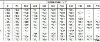
The optimal heating temperature of the workpiece flange when drawing parts from aluminum alloys and brass is given in table. 96.
Table 96
| Name and brand of material | Optimal temperature, °C |
| Aluminum alloys V95A-T1, D16A-T | 480-500 |
| Aluminum alloys D16A-M, AMtsA-M | 320-340 |
| Brass L62 | 450-480 |
The limit values of the elongation coefficient of cylindrical parts made of aluminum alloys and brass at the optimal temperature of local heating of the flange are given in table. 97.
Table 97
| Name and brand of material | Draw coefficient mpr | hpr/d* |
| Aluminum alloy AMgA-M | 0,39 | 1,44 |
| Aluminum alloy AMtsA-M | 0,42 | 1,18 |
| Aluminum alloy D16A-M | 0,37 | 1,62 |
| Aluminum alloy D16A-T | 0,33 | 2,10 |
| Aluminum alloy V95A-T1 | 0,32 | 2,20 |
| Brass L62 | 0,33 | 2,10 |
*hpr/d - the ratio of the maximum height of a cylindrical part to the diameter of the hood.
The limiting values of the elongation coefficient of square and rectangular hollow parts at the optimal temperature of local heating of the flange and the radii of curvature of the corner sections in the plan are given in Table. 98.
Table 98
| Name and brand of material | Radius of curvature of the corner section in plan rп, mm | Square hollow parts | Rectangular hollow parts | ||
| Draw coefficient m1pr | hpr/dу | Draw coefficient m1pr | hpr/dу | ||
| Aluminum alloy AMgA-M | 2,5 | 0,075 | 1,50 | 0,083 | 1,46 |
| Aluminum alloy AMtsA-M | 0,078 | 1,44 | 0,086 | 1,44 | |
| Aluminum alloy D16A-M | 0,072 | 1,58 | 0,079 | 1,51 | |
| Magnesium alloy MA1M | |||||
Materials used for sheet stamping
When choosing a material for cold stamping, it is necessary to take into account the performance properties of obtaining parts and the ability of the material to be processed by pressure.
Carbon steel of ordinary quality (GOST 380-2005, grades St0, St1, St2, etc.) is used to stamp parts that carry light loads and household products. Parts with increased strength requirements are stamped from high-quality carbon steel (GOST 1050-88, grades 10, 15, etc.). High-quality structural boiling steel (GOST 1050-88, grades 05kp, 08kp, 10kp, 15kp, etc.) is widely used for sheet stamping.
For the manufacture of complex facing parts (for example, car body parts), 08kp steel is used - non-aging steel with a vanadium additive, 08sp or 08ps - corresponding to mild or semi-mild steel, deoxidized with aluminum.
For the manufacture of critical stamping parts, various alloy steels are used: 10G2A, 12G2A, 20KhGSA, 25KhGSA, etc.
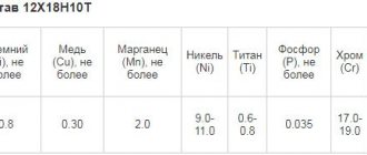
In sheet stamping of non-ferrous metals and their alloys, the following are most widely used: aluminum - A1, A2, A3; BP, BP1; aluminum alloys - D1, D6, D16, AMg1, AMg5, AMts; copper - M1, M2, M3; brass - L62, L68, L70; magnesium alloys, titanium and its alloys, some non-metallic materials: cardboard, paper, leather, rubber, asbestos, methyl methacrylate (organic glass), etc.