- September 12, 2020
- Repair Tips
- Ivan Gresko
Many radio amateurs and home craftsmen are familiar with this heating device. It can be used to connect various parts made of ferrous and non-ferrous metals. Owners are often interested in the question: how to repair a soldering iron at home? The fact is that this tool can fail as a result of improper handling. Of course, you can take it to a workshop and have it done by a professional. However, many owners prefer to do it on their own.
How to fix a soldering iron? This is especially of interest to those who have just begun to master this heating device. In general, this task will not be difficult to cope with if you identify the cause of the breakdown and strictly adhere to a certain algorithm of actions. Information on how to repair a soldering iron at home is presented in this article.
Components of the tool
Before you are interested in how to repair a soldering iron at home, you should know how it works. In this case, if there is a breakdown, it will be easier for you to determine the cause and fix it. The soldering iron device is represented by the following elements:
- Copper rod. It is wrapped in insulating material and housed in a steel tube.
- Heater. This task is performed by nichrome thread.
- Sting. They use solder to directly connect metal parts.
- With a pen. Thanks to it, the master can hold the soldering iron.
- Cord equipped with a plug.
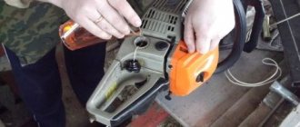
Elimination of tip overheating
Refinement of the power regulator
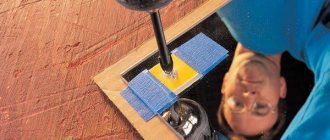
A homemade contact sensor is made from an old Soviet capacitor and balls from a bearing. The device is placed on the factory board without modifications to the case. When the soldering iron is placed on the stand with the tip up, the sensor opens the circuit and the heating temperature decreases. When we start soldering, the contacts inside close and the tip warms up to the set temperature in accordance with the position of the regulator.
Let's look at a few more examples of such modifications in relation to various models of soldering devices.
Description of design
The copper rod is an effective conductor of heat that flows from the heater to the tip. The rod is located in a steel tube wrapped in mica or glassy tissue. A wire is wound over the mica, which acts as a heating element. To prevent heat loss and short circuit, the nichrome winding is insulated, covered with asbestos for this purpose. The ends of the spiral are connected to the conductors of the power cord. To make the design more reliable and the connection point not to overheat from the heat generated, the nichrome spiral is bent in half and folded in half. Additionally, the point of contact of the spiral with the copper wire is crimped using an aluminum plate. In addition, the twisting area is covered with an insulating tube. All of the above elements are housed in a metal casing. It is mounted on a handle, which can be made of wood or thermoplastic. Inside the handle there is a special channel for the electrical cord. The housing is fixed to the metal tube using overlay rings. Those who are interested in how to repair a soldering iron at home should also know about the technical characteristics of the electrical appliance.
Soldering iron design: diagram and principle of operation
See also reviews and articles:
- What is a soldering station?
- What to choose - a soldering iron or a soldering station?
- How much does a good soldering iron cost?
- Which soldering iron is best for a beginner radio amateur?
- Choosing the right consumables for soldering
Electrical circuit of a soldering iron
The circuit of a soldering iron is quite simple; it includes several basic elements: a plug, a spiral made of nichrome, and a wire.
The plug and wire are used if the soldering iron is powered from the mains, but there are also soldering irons where the power comes from a built-in source. The spiral is the main part of the soldering iron; thanks to it, electricity is converted into heat, after which the parts being processed are heated and soldered.
The heating temperature of the soldering iron, or rather its tip, is not adjustable, so to maintain the required temperature value, you can connect it through a power regulator to be able to adjust it manually and subsequently maintain it during operation.
The power of the soldering iron is selected depending on the type of work to be done: small parts are soldered with a low-power device. This is important because if you take a soldering iron with high power, its tip will not penetrate into hard-to-reach places, and there is also a high probability of overheating. For large parts and thick wires, you need a more powerful soldering iron (40 Volts and above). If the power is insufficient, the soldering will be of poor quality with the formation of voids.
The selection of a soldering iron also depends on the voltage. A soldering iron with a voltage of 12 Volts is suitable for use in passenger vehicles, 24 Volts - in trucks, 27 Volts - in air transport, 36 Volts - in rooms with high humidity with mandatory grounding of the electrical equipment located there.
If you have a soldering iron designed for 12 Volt voltage, and you want to convert it to 220 Volt, you will have to wind the spiral in several layers, which will create difficulties when working with small-sized parts.
If the network matches the soldering iron, then you can work from alternating and direct voltage. This is because of the nichrome material the heater is made from.
Typically, the voltage in soldering tools is exactly 220 Volts. To work in rooms with high humidity or dust, use devices with voltages up to 42 Volts. This is a necessary safety measure that eliminates the possibility of electric shock.
How does a soldering iron work?
A soldering iron is a device that can be used to connect parts together. The intermediary between these parts can be solder - a substance that, under the influence of high temperature, melts and turns into a liquid. After this action stops, the solder instantly hardens and provides an unbreakable connection. This tool is indispensable for people working with electronics, because thanks to it you can not only connect parts, but also separate them.
You don’t have to be a genius and carefully study the internal structure of a soldering iron in order to be able to use it, but if it suddenly fails, then this information can help.
Soldering irons released at different times undoubtedly have some differences, however, the main parts are similar for all models. The structure of a soldering iron looks like this: the main part is a rod that is made of red copper. When exposed to temperature, it is this that melts the solder. Why was this particular metal chosen? This is because it has a high thermal conductivity coefficient. The rod at the end is made in the shape of a wedge, so that working with small parts is easier and more convenient.
The second important part of the soldering iron is a tube made of steel where the copper rod is placed. This design is called a heating element. The top of the said tube is wrapped with mica. What is it for and how to replace mica in a soldering iron? Mica can be replaced with ordinary fiberglass by winding nichrome wire on top. When an electric current passes through it, it will heat up and transfer heat to the tube. This will also cause the rod to heat up. On the nichrome wire there is another layer of mica, which is necessary to protect the spiral from interaction with the soldering iron body, which increases the level of safety of the device. In addition, the mica layer is needed in order to retain heat and not waste heat on the body of the device.
The handle of the device can be made of wood or special plastic, but in no case made of metal.
As for the wires, they are connected to the terminals of nichrome wire, and to make the connection as strong as possible, you can use aluminum clamps that are securely soldered. Their purpose is not limited to providing a high-quality connection; they are also designed to remove excess heat. The higher the power of the soldering iron, the higher the temperature to which the copper wires are exposed, and the more necessary the presence of aluminum clamps is. You need to know this in case when repairing a soldering iron the question arises about removing these clamps.
The heating element is located inside the steel body of the tool. Depending on the model, the body may have threads for fixing the rod, as well as holes for heat dissipation, which are located near the handle.
Consider, for example, an induction soldering iron and how it works. It begins to heat up thanks to the inductor coil. The tip is coated with a ferromagnetic composition, which affects the creation of a magnetic field. The core begins to warm up. When the degrees reach a certain level, heating stops. With further cooling, the ferromagnetic characteristics are restored and the soldering iron again begins to increase the temperature. That is, the temperature is maintained automatically without the use of any temperature sensors or additional electronic devices.
Unlike an induction soldering iron, a gas soldering iron is a self-contained device. It can be used anywhere.
The flame arising from the combustion of gas is the source of heat from which the tip is heated. Gas is filled into the soldering iron using a regular can.
Soldering iron operating principle
The operation scheme is as follows: when the soldering iron is connected to the electrical network, the nichrome spiral passes an electric current through itself and it heats up. Heat is transferred to the copper rod, which can cause its temperature to rise to very high levels, about 300 degrees. Because of this, the solder melts under the influence of the tip (rod) and solders the parts.
There are many types of soldering irons, they can be different in power and have different types of heating elements. In cases where you need to solder large parts or wires with a large cross-section, you need soldering irons with a large tip and a power of about 100 watts. Soldering irons with a power of 50 to 80 watts have found their application for repairing electrical equipment and radio equipment. Soldering irons for soldering small elements should have a thin tip and low power - about 20 watts.
Nowadays, many types of soldering irons are produced, one of which is with a ceramic heater. Such soldering irons are very capricious; if a little water gets on its heating element or it falls, it may fail and there will be no possibility of repair. The fact is that the heating element consists of a very thin ceramic plate, and inside there is a thin nichrome spiral. At the slightest impact, this thin wire breaks and the soldering iron cannot be repaired.
There are many types of soldering irons and their design and operating principles differ from each other. The choice of soldering iron depends on the nature of the problem that it must solve.
- Rod ones are the most common type. How they work and what they consist of was discussed a little higher. This variety has received approval and recognition from many craftsmen working at home; they do a good job with both household appliances and wires.
- Pistol - similar in appearance to weapons, also used for repair work. The working part and the handle are located at an angle of 90 degrees to each other - this is very convenient for some jobs.
- Soldering stations are equipped with control units that allow you to make various settings - power, temperature, current, etc.
Soldering stations can be divided into several types, on which their operating principle depends:
- Digital - the principle of operation is similar to rod soldering irons. The difference is that here you can set parameters for the execution of work.
- Infrared - soldering occurs due to infrared radiation. The wavelength is up to 10 microns, and the heating zone is up to 60 mm.
- Thermal air - during its operation, the solder melts under the influence of hot air, the direction of which is regulated by the nozzle.
Calculation of the resistance of a nichrome spiral
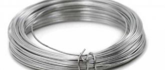
A nichrome spiral can be found in stores in the form of a coil with wound wire. This form is very convenient and compact. It is a heating element and is made of a chromium-nickel alloy. Hence the name - nichrome.
The two most famous brands are X20N80 (73% nickel and 23% chromium) and X15N60 (60% nickel and 18% chromium). The first is called the classic type, and the second was created to reduce the cost of wire; here the composition of nickel and chromium is reduced, but the amount of iron is increased.
After obtaining these two main alloys, many modifications were obtained that have greater resistance to oxidation at increased temperatures. These types are applicable for those heated elements that interact with air.
The main property of nichrome wire is its ability to resist electric current. The nichrome spiral can be used not only as a heating element, but also as a material for resisting electrical circuits. For heaters, spirals are used, which are used in fan heaters and thermoreflectors, for electric heating and in the shades of heating devices, as well as in the form of a heater for thermal equipment.
Alloys produced in vacuum furnaces are used for industrial equipment.
Spirals from the two most common brands indicated differ from the rest in that their resistance does not change too much when the temperature changes. It is often used for resistors, as well as various parts.
A nichrome spiral can be made at home. All you need is wire of a suitable brand. The calculation of a nichrome spiral depends on the resistivity of the wire and the required power. When calculating the power, you should not miss the highest current at which the temperature of the nichrome spiral reaches the desired value.
Reference books have long been invented to calculate current strength and temperature, but that’s not all. The conditions under which the heater is operated must be taken into account. If the heater is immersed in water, the heat transfer will increase and the current can be increased by half the calculated one. If the heater is closed, then heat removal will be reduced, and the current will need to be reduced by up to 50%.
The spiral pitch is of no small importance: turns located close to each other contribute to greater heating; if the pitch is large, then cooling occurs faster. All reference values are given for horizontal type heaters; if the angle changes, the readings will change.
Using school knowledge, knowing the value of power and voltage, we find the current strength, and then, using Ohm’s law, known to everyone, we easily find the resistance.
The length of the spiral depends on the diameter of the wire and the resistivity, so the formula will be as follows: L=(Rπd2)4ρ, where L is the length; R – resistance; d – wire diameter; π – 3.14; ρ – resistivity of the material (nichrome).
You can simply use the tabulated value of linear resistance, as well as temperature corrections.
Then the calculation will be different: L=R/ρld, where ρld is the resistance of a wire 1 meter long and diameter d.
To geometrically calculate a nichrome spiral, namely the number of turns, we need the formula N=L/(π(D+d/2)), with the length of one turn equal to π(D+d/2).
Of course, virtually no one winds wire by hand. It is much easier to go to the store and buy the desired spiral with all the necessary characteristics.
Published: 2020-04-13 Updated: 2021-08-30
Author: Electronoff Store
SUITABLE PRODUCTS
- YIHUA 8858-i hot air soldering station, portable, with display 5 reviews
Buy
1980 UAH
Code 30457
in the shop
- Gas torch soldering iron INTERTOOL GB-0021, with piezo ignition 4 reviews
Buy
116 UAH
Code 29455
in the shop
- Solder in a tube Cynel LC60-1.00/F 190°C 1mm 4 reviews
Buy
50 UAH
Code 1201
in the shop
- Solder Cynel Sn60Pb40 1mm 100g (POS-60F) 3 reviews
Buy
227 UAH
Code 1123
in the shop
- Soldering iron gun ZD-80 30/130W 4 reviews
Buy
179 UAH
Code 725
in the shop
- Gas torch soldering iron GB-0020 Intertool 3 reviews
Buy
119 UAH
Code 21612
in the shop
- Soldering station YIHUA 852 4 reviews
Buy
1735 UAH
Code 29162
in stock
- Soldering station YIHUA 853AAA (with preheater) 2 reviews
Buy
6099 UAH
Code 29548
to order
- Soldering station YIHUA 853D (with power supply and USB) 2 reviews
Buy
3100 UAH
Code 29545
to order
- Infrared soldering station YIHUA 1000B 2 reviews
Buy
15000 UAH
Code 28836
to order
- Soldering iron gun ZD-723N 40W (Euro plug) 1 review
Buy
179 UAH
Code 15364
to order
- Soldering iron gun ZD-80 30/130W (Euro plug) 3 reviews
Buy
210 UAH
Code 724
to order
Share on social networks
Comments on the article “Soldering iron design: diagram and principle of operation”
- Alexey 06/06/2020 18:24
I read the article from beginning to end. I liked the article and gave me some thoughts. There is a soldering iron in the household, and if it broke, I simply threw it in the trash. Now I’m thinking that it can be repaired by replacing the heating element, this is certainly cheaper than the cost of a new soldering iron.Rating star star star star star
Leave your comment
Error
How does the device work?
Those who do not know how to repair a soldering iron with their own hands should familiarize themselves with the principle of operation of an electrical device. The soldering iron functions by converting electricity into heat. As a result, heat is transferred through the heated spiral to the rod, as a result of which the tip becomes heated. You should know that in the area where soldering is carried out, the temperature varies from 400 to 4500 °C. As a result, a mixture of viscous-liquid consistency is formed. Subsequently, it fills the cavity between the parts being soldered. When the mixture cools, the metal parts are securely connected.
Induction
The induction soldering iron is currently the pinnacle of technical achievements in the field of metal soldering with eutectic solders. In essence, an induction-heated soldering iron is a miniature induction furnace: the HF EMF of the inductor coil is absorbed by the metal of the tip, which is heated by Foucault eddy currents. Making an induction soldering iron with your own hands is not so difficult if you have a source of HF currents at your disposal, for example. computer switching power supply, see e.g. plot
Video: induction soldering iron
However, the quality and economic indicators of induction soldering irons for conventional soldering work are low, which cannot be said about their harmful effects on health. In fact, their only advantage is that the tip stuck to the holder in the body can be torn out without fear of tearing the heater.
Induction mini-soldering irons of the METCAL system are of much greater interest. Their introduction in electronics production made it possible to reduce the percentage of defects due to installer errors by 10,000 times (!) and lengthen the work shift to a normal one, and the workers left after it cheerful and capable in all other respects.
The structure of a METCAL type soldering iron is shown at the top left in Fig. The highlight is the ferronickel coating of the tip. The soldering iron is powered by RF at a precisely maintained frequency of 470 kHz. The thickness of the coating was chosen such that at a given frequency, due to the surface effect (skin effect), Foucault currents were concentrated only in the coating, which gets very hot and transfers heat to the tip. The tip itself turns out to be shielded from EMF and induced potentials do not arise on it.
Design of induction soldering irons for microcircuits
When the coating warms up to the Curie point, above which the ferromagnetic properties of the coating disappear in temperature, it absorbs EMF energy much weaker, but still does not allow RF into the copper, because maintains electrical conductivity. Having cooled below the Curie point on its own or due to heat transfer to the soldering, the coating again begins to intensively absorb EMF and heats up the tip. Thus, the tip maintains a temperature equal to the Curie point of the coating with an accuracy of literally one degree. The thermal hysteresis of the tip is negligible, because determined by the thermal inertia of the thin coating.
To avoid harmful effects on people, soldering irons are produced with non-replaceable tips, tightly fixed in a cartridge of a coaxial design, through which they are supplied to the RF coil. The cartridge is inserted into the soldering iron handle - a holder with a coaxial connector. Cartridges are available in 500, 600 and 700 types, which correspond to the Curie point of the coating in degrees Fahrenheit (260, 315 and 370 degrees Celsius). Main working cartridge – 600; The 500th is used to solder especially small smds, and the 700th is used to solder large smds and scatterings.
Note: to convert Fahrenheit to Celsius, you need to subtract 32 from Fahrenheit, multiply the remainder by 5 and divide by 9. If you need to do the opposite, add 32 to Celsius, multiply the result by 9 and divide by 5.
Everything is great about METCAL soldering irons, except the price of the cartridge: for “(company name) new, good” – from $40. “Alternative” ones are one and a half times cheaper, but are produced twice as fast. It is impossible to make a METCAL tip yourself: the coating is applied by spraying in a vacuum; Galvanic at the Curie temperature instantly peels off. A thin-walled tube mounted on copper will not provide absolute thermal contact, without which METCAL simply turns into a bad soldering iron. Nevertheless, making an almost complete analogue of the METCAL soldering iron yourself, with a replaceable tip, although difficult, is possible.
Induction for smd
The design of a homemade induction soldering iron for microcircuits and SMD, similar in performance to METCAL, is shown on the right in Fig. Once upon a time, similar soldering irons were used in special production, but METCAL completely replaced them due to better manufacturability and greater profitability. However, you can make such a soldering iron for yourself.
Its secret is in the ratio of the shoulders of the outer part of the tip and the shank protruding from the coil into the inside. If it is as shown in Fig. (approximately), and the shank is covered with thermal insulation, then the thermal focus of the tip will not go beyond the winding. The shank will, of course, be hotter than the tip of the tip, but their temperatures will change synchronously (theoretically, thermohysteresis is zero). Once you have set up the automation using an additional thermocouple that measures the temperature of the tip tip, you can then solder in peace.
The role of the Curie point is played by a timer. It is reset to zero by a signal from the thermostat for heating, for example, by opening the key that shunts the storage tank. The timer is started by a signal indicating the actual start of the inverter operation: the voltage from the additional winding of the transformer of 1-2 turns is rectified and unlocks the timer. If you do not solder with a soldering iron for a long time, the timer will turn off the inverter after 7 seconds until the tip cools down and the thermostat issues a new heating signal. The point here is that the thermal hysteresis of the tip is proportional to the ratio of the times of switched-off and switched-on heating of the tip O/I, and the average power on the tip is proportional to the reverse I/O. Such a system does not maintain the temperature of the tip up to a degree, but it provides +/–25 Celsius with a working tip of 330.
About voltage
If there is a need to repair the device, take into account the voltage indicator. Depending on the model, its value may be:
- 220 V. This value is mainly found in domestic models.
- 12-42 V. Devices with a reduced voltage transformer are used in conditions with high levels of dust or humidity in order to protect the technician from electric shock.
- 5 V. Miniature USB soldering irons have this indicator.
Rules for using power tools
On the shelves of construction stores you can find different models of electric soldering irons that operate on mains power - from 12 to 220 W. The process of choosing a tool should take into account the safety of the working craftsmen and the voltage in the electrical network at the work site.
Attention
In rooms with high humidity, where grounding is provided, it is permissible to use soldering irons with a power of 36 Watt, 25 Watt and lower. In this case, it is necessary to ground the instrument body.
If the instrument is made independently, then a thin wire will be required for its correct reconstruction. It will be wound onto a spiral. The required power is from 12 to 100 W, even more is possible. The material will spread evenly over the surface of the plates if the melting temperature exceeds the temperature in the soldering iron itself.
About power
This technical characteristic determines the functionality of the soldering iron. For example, for home use to work with wires, a power of 30 W will be sufficient. These soldering irons are mainly used by radio amateurs. Professional installers operate devices with power up to 60 W. Such devices are convenient for soldering wires and cables of various diameters. Soldering irons over 60 W are used in automobile workshops. These soldering irons are suitable for tinning large metal products. It is noteworthy that the higher the power indicator, the larger and heavier the device itself. With increasing power, the size of its tip (sting) also increases. Thus, a soldering iron with more power will heat up the soldering area better. What to do if your electric soldering iron breaks down? How to fix the device?
Applications and types
- The AC electric soldering iron with spiral heating of the core operates from a standard power supply network for household equipment at 220V 50-60Hz.
- A cordless electric soldering iron is used for desoldering wires and other small-sized elements where high power up to 15 W is not required;
- There are varieties of gas soldering irons that are used for strong heating of metal elements and refractory alloys;
- To work with low-melting tin during the installation and repair of radio equipment, pistol-type soldering irons with pulsed voltage supply are widely used. When you press the trigger, the tip of the soldering iron heats up; after soldering is completed, the trigger is released and the heating element cools down;
- Soldering irons with ceramic rods have a long service life and allow you to select the desired temperature mode and power consumption;
Soldering iron with ceramic tips on the rod
- Induction soldering irons are widely used. An inductive coil creates a magnetic field on the ferromagnetic tip, which heats the core. When the magnetic properties of the core are lost, heating stops; this is a significant drawback of such models.
An electric soldering iron is used as a hand tool. With its help, solder is melted to a liquid state, which fills the cracks and irregularities of heated metal elements at the joints, for which alloys of low-melting metals are used:
- tin;
- lead;
- zinc;
- nickel;
- copper and others.
The melting temperature of solders must be less than the melting temperature of the metal elements being connected.
The industry produces different types of soldering irons. The most commonly used in industry and at the household level are spiral soldering irons, which are worth describing in more detail.
Repairing a burnt-out soldering iron. Where to begin?
Before you repair the soldering iron yourself, you should disassemble it. This is necessary in order to get to the heating element, namely the nichrome wire. For this purpose, unscrew the mounting bolts and disassemble the device. Overall you will only need to remove two bolts. When they are removed, take out the soldering iron “filling”, which is contained inside the metal case. To do this, you will have to carefully open the case itself. At this stage you must be very careful not to damage the thin and very fragile insulation. If handled carelessly, it may fall apart.
Causes of soot
Some beginners or those who are used to working with copper tips make a fatal mistake. They clean the soldering iron tip with sandpaper, files or blades from a stationery knife. This is only true for uncoated copper tips. This method is unacceptable in principle for “eternal” stings.
There is a high risk of damaging the outer layer of the tip (a thin metal alloy), which can lead to cracks and further destruction. In addition, despite its appearance, the soot layer itself does not exceed some microns. So how to clean a soldering iron from such deposits? There are several ways.
Restoring the heating element
When you get to the heating element, carefully inspect the nichrome wire. It may happen that several turns of wire are burnt out. To restore the heating element you need to do the following. Take an old broken soldering iron and remove a small piece of wire from it. Next, connect it and wind it instead of the burnt out turns. According to experts, when connected without adding wire, the spiral will burn out again due to reduced resistance. You need to wind it so that the turns do not touch each other. Then connect the power cord.
Simple from resistor
Calculation
The simplest soldering iron can be made from a wire resistor; this is a ready-made nichrome heater. It is also easy to calculate: when the rated power is dissipated in free space, the wirewound resistors heat up to 210-250 degrees. With a heat sink in the form of a sting, the “wireworm” maintains a long-term power overload of 1.5-2 times; The temperature of the tip will not be lower than 300 degrees. It can be increased to 400, giving a power overload of 2.5-3 times, but then after 1-1.5 hours of operation the soldering iron will need to be allowed to cool.
Calculate the required resistor resistance using the formula: R = (U^2)/(kP), where:
R – required resistance;
U – operating voltage;
P – required power;
k – the above power overload factor.
For example, you need a 220 V 100 W soldering iron for soldering copper pipes. The heat transfer is large, so we take k = 3. 220^2 = 48400. kP = 3*100 = 300. R = 48400/300 = 161.3... Ohm. We take a 100 W resistor 150 or 180 Ohm, because There are no “wireworms” at 160 Ohms, this rating is from the range of 5% tolerance, and “wireworms” are no more accurate than 10%.
The opposite case: there is a resistor with a power p, what power can you make a soldering iron from it? What voltage should it be powered from? Let's remember: P = U^2/R. Let's take P = 2 p. U^2 = PR. We take the square root of this value and get the operating voltage. For example, there is a 15 W 10 Ohm resistor. The power of the soldering iron is up to 30 W. We take the square root of 300 (30 W * 10 Ohm), we get 17 V. From 12 V, such a soldering iron will develop 14.4 W, you can solder small things with low-melting solder. From 24 V. From 24 V – 57.6 W. The power overload is almost 6 times, but occasionally and for a short time it is possible to solder something large with this soldering iron.
Manufacturing
Making a soldering iron from a resistor
How to make a soldering iron from a resistor is shown in Fig. higher:
- We select a suitable resistor (item 1, see also below).
- We prepare the parts of the tip and fasteners for it. Use a file to select a groove on the rod for the ring spring. Threaded blind holes are made for the bolt (screw) and the tip, pos. 2.
- We assemble the rod with the tip into the tip, pos. 3.
- We fix the tip in the resistor-heater with a bolt (screw) with a wide washer, pos. 4.
- We attach the heater with the tip to a suitable handle in any convenient way, pos. 5-7. One condition: the heat resistance of the handle is not lower than 140 degrees; the resistor terminals can heat up to this temperature.
Subtleties and nuances
The soldering iron described above made from 5-20 W resistors was made by many (including the author in his pioneer days) and, having tried it, they were convinced that it could not be used seriously. It takes an unbearably long time to heat up, and it only solders small things with a poke - the ceramic layer interferes with the heat transfer from the nichrome spiral to the tip. This is why the heaters of factory soldering irons are wound on mica mandrels - the thermal conductivity of mica is orders of magnitude higher. Unfortunately, it is impossible to roll mica into a tube at home, and rolling 0.02-0.2 mm nichrome is not for everyone either.
But with soldering irons from 100 W (resistors from 35-50 W) the matter is different. The ceramic thermal barrier in them is relatively thinner, on the left in the figure, and the heat reserve in the massive tip is an order of magnitude greater, because its volume grows by the cube of its dimensions. It is quite possible to qualitatively solder a joint of 1/2″ 200 W copper pipes with a resistor soldering iron. Especially if the tip is not prefabricated, but one-piece forged.
Wirewound resistors, suitable and unsuitable for making soldering irons
Note: wirewound resistors are available for dissipation power up to 160 W.
Only for the soldering iron you need to look for resistors of old types PE or PEV (in the center in the figure, still in production). Their insulation is vitrified and can withstand repeated heating to light red without losing its properties, only darkening as it cools. The ceramic inside is clean. But the resistors C5-35V (on the right in the figure) are painted, and so are the insides. It is completely impossible to remove paint from the channel - ceramics are porous. When heated, the paint becomes charred and the tip sticks tightly.
Why doesn't the soldering iron heat up? How to fix it?
Most often, the cause of this malfunction is poor contacts. First check the voltage supply. If it turns out that the current power is normal, then most likely the malfunction is caused by an incorrect location of the tip. This happens especially often in electrical appliances with retractable rods and screw terminals. Often the tip wears off or for some other reason ends up being too protruded from the body. If the working surface is located normally, then its end part in the form of a core is completely located in a mica tube. Thus, the contact of the rod with the heating element occurs fully, due to which the tip heats up more. If it is removed from the tube at least halfway, the heating intensity will decrease significantly. Repairing the device is easy. Home craftsmen insert the sting deeper into the body and fix it. It may be that the rod turns out to be too short. In this case, it is replaced. Also, the soldering iron may not work due to scale on the tip. It is removed, if necessary, and then the surface is cleaned using ordinary fine-grained sandpaper or a needle file.
The sting is then heated and dipped in rosin, after which its tip is rubbed on a braid with solder. As a result of such actions, the rod will be covered with an even layer of solder. Experts recommend performing this procedure more often with soldering irons equipped with copper rods, since scale forms on them faster. Also, the soldering iron may not heat up due to improper sharpening of the tip. For effective heat transfer, the working surface must have the shape of an oval bevel.
Step-by-step instructions on how to repair it yourself
Soldering iron repair begins with calculating the resistance of the heating element or winding. The voltage and resistance values of an electrical appliance allow you to calculate its power consumption. For example, the resistance in the winding of a soldering iron with a power of 60 W and powered from a 36 V network should be equal to or slightly more than 22 Ohms.
For repairs, you need to prepare the following tools:
- pliers;
- sharp knife;
- ceramic resistance “PEV-10”;
- asbestos thread.
A ceramic resistor is pre-prepared. The power wires must be close to its base to test the electronic power and heat dissipation.
You need to have nichrome wire on hand; its diameter must correspond to the parameters of the winding. The coils are laid closely. When heated, the surface of the nichrome wire will oxidize, creating an insulating layer. The wound layer, which according to the rules should not be placed in the first row, is covered with mica and placed in the second row.
Important
Before repairing a soldering iron, it is advisable to have its diagram at hand. You can draw it by reading the instructions or while disassembling the tool into its component parts.
About using solder
If you notice that your tool heats up weakly, then most likely you have chosen the wrong solder. For example, for low-power electrical appliances rated at 26 watts, it is not recommended to use low-tin solder (POS-30). You will not melt this solder with this soldering iron. It is best to get POS-60 or POS-61 solder. Other solders with a high lead content are suitable for higher power electrical appliances.
About rewinding an electrical appliance
Beginners often ask the question: how to rewind a soldering iron? Judging by numerous reviews, very often device repair is limited to replacing the burnt nichrome winding. Before starting this procedure, use a special table to calculate the diameter of the wire, as well as the number of turns. For example, how to repair a 200W soldering iron? To do this, select the soldering iron power consumption indicator of 200 W (in the left column of the table). To this value, the winding resistance at a voltage of 220 V will be 242 Ohms. It will be best to rewind the entire reel.
In this case, there will be no weak points in the device. It is very important that the new wire has the same parameters as the old winding. If it is not possible to select a similar insulating layer, then it can be replaced with mica in the form of a tube or plates. You can also use heat-resistant fiberglass or asbestos gaskets to make an insulating layer. After the insulation is ready, wind the winding (first layer) around it. Next, put another layer of insulation on the turns and wind the winding again (second layer). Now all that remains is to connect the ends of the wire to the power cord.
Calculation of required parameters
In order to repair a failed soldering iron, you can change its parameters, taking into account the intended purpose, i.e. what do you use a soldering iron for (soldering a pan or a microcircuit). In this case, special tables are used, where the following values are specified for selection:
- soldering iron power consumption;
- supply voltage;
- resistance of nichrome wire.
Operating principle of a synchronous generator
The required coil resistance for various power and voltage values is pre-calculated and tabulated.
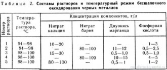
Selecting the resistance of the spiral (nichrome wire) according to the power and voltage of the soldering iron Ohm
| Power, watts | Voltage, Volts | ||||
| 12 | 24 | 36 | 127 | 220 | |
| 12 | 12 | 48,0 | 108 | 1344 | 4033 |
| 24 | 6,0 | 24,0 | 54 | 672 | 2016 |
| 36 | 4,0 | 16,0 | 36 | 448 | 1344 |
| 42 | 3,4 | 13,7 | 31 | 384 | 1152 |
| 60 | 2,4 | 9,6 | 22 | 269 | 806 |
| 75 | 1,9 | 7,7 | 17 | 215 | 645 |
| 100 | 1,4 | 5,7 | 13 | 161 | 484 |
To rewind a soldering iron with a power of 36 W at a supply voltage of 220V, the table shows that the winding resistance should be 1344 Ohms. Next, you can take the existing wire, attach the Ohmmeter terminal to the end, move the second terminal along the unwound wire until it reads 1334 Ohm. At this mark, cut off the measured section and wind it onto the soldering iron coil.
Resistance of a meter nichrome wire to its diameter
| Diameter, mm | 1,0 | 0,9 | 0,8 | 0,7 | 0,6 | 0,5 | 0,4 | 0,3 | 0,2 | 0,1 | 0,08 | 0,07 |
| Ohm/m | 1,4 | 1,7 | 2,2 | 2,89 | 3,93 | 5,6 | 8,75 | 15,7 | 34,6 | 137 | 208 | 280 |
You can use the above table. Measure the diameter of the wire with a micrometer and use the table to determine the required length of wire in the coil. So, if the wire diameter is 0.08 mm, the resistance per meter will be 208 Ohms. The required resistance is 1334 Ohm / 208 Ohm = 6.4 m. This results in the length of the wire that should be wound on the coil.
The turns on the winding are laid closely, heating up red-hot, the scale of the nichrome coating forms an insulating interturn layer. When the length of the coil is not enough, an insulating layer, fiberglass, asbestos or mica is applied, and a second layer is wound. Almost every coil consists of several layers , it is very important that it is placed in a protective casing.
Broken wiring
How to fix a soldering iron with your own hands if the electrical cord is faulty? Judging by numerous reviews, this reason for device failure is considered the most common. You can correct the situation on your own. Many owners simply replace the plug or cord. Of course, it all depends on which part the break occurred in. This defect is correctable, and you can fix it yourself. To determine exactly where the break occurred, you will need to acquire a special device, namely a multimeter. Use the probes of this device to examine the wiring. In the place where the break occurred, you need to reconnect the wires and insulate them.
How to fix a soldering iron with a regulator yourself?
Such electrical devices are equipped with a special device for adjusting the temperature of the tip. Using this soldering iron is quite convenient. The master knows that it is heating up thanks to the LED, which glows while the tip is heating. When the working surface reaches the desired temperature, the LED will go out, after which you can begin soldering. According to reviews from owners of such soldering irons, these power tools often fail. For example, there are times when buttons come off or an LED does not light up. Some home craftsmen wrap buttons with insulating tape. To repair the device, you must first carefully disassemble it. When you do this, you will see the op amp. It is a microcircuit in which, most likely, one of the small batteries has become disconnected. It needs to be reattached. For this purpose, you first need to clean the “legs” of the battery, tin them, and then solder them in their original place. After completing these steps, the soldering iron can be assembled and tested.
Simplest
Let's not get into the complications for now. Let's say we need a regular 220V soldering iron without any fuss. We go to choose and see that the difference in prices reaches 10 times or more. Let's figure out why. First: heater, nichrome or ceramic. The latter (not “alternative”!) is practically eternal, but if the soldering iron is dropped on a hard floor, it can break. The tip of ceramic soldering irons is necessarily non-replaceable, which means you need to buy a new one. And a nichrome heater, if the soldering iron is not forgotten to be turned on at night, lasts more than 10 years; with occasional use - over 20. And in extreme cases, it can be rewound.
The difference in price has now been reduced to 3-4 times, what else is the matter? In a sting. Nickel-plated copper with special additives is poorly dissolved by solder and burns very slowly in the soldering iron holder, but is expensive. Brass or bronze heats up worse, and it is impossible to solder SMD with it - the temperature hysteresis cannot be brought back to normal due to the thermal conductivity of the material being much worse than that of copper. The red copper tip is eaten by solder and swells quite quickly from copper oxide, but it is cheaper.
Note: a tip made of electrical copper (a piece of winding wire) is unsuitable for a conventional soldering iron - it quickly dissolves and burns. However, for SMD such a sting is just right, its thermal conductivity is the highest possible, and thermal inertia and hysteresis are minimal. True, you will have to change it often, but the sting is about the size of a match or less.
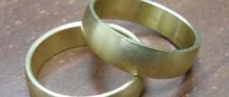
Burning and swelling of the red copper tip can be dealt with simply by being careful: after finishing the work and allowing the soldering iron to cool, take out the tip, peel off the oxide, tapping it on the edge of the table, and blow out the channel of the soldering iron holder. Solder dissolution is worse: sharpening the tip is often inconvenient and it quickly wears out.
You can make a soldering iron tip from ordinary red copper many times more resistant to the action of molten solder by not sharpening its working end, but by forging it to the desired shape. Cold copper can be forged perfectly with an ordinary metalworker's hammer on the anvil of a bench vise. The author of this article has had a forged tip in the ancient Soviet EPSN-25 for more than 20 years, although this soldering iron is in use, if not every day, then certainly every week.