There are a lot of diagrams of various soldering stations on the Internet, but they all have their own characteristics. Some are difficult for beginners, others work with rare soldering irons, others are not finished, etc. We focused specifically on simplicity, low cost and functionality, so that every novice radio amateur could assemble such a soldering station. Please note that we also have an SMD version of this device!
What is a soldering station for?
An ordinary soldering iron, which is connected directly to the network, simply heats constantly with the same power. Because of this, it takes a very long time to warm up and there is no way to regulate the temperature in it. You can dim this power, but achieving a stable temperature and repeatable soldering will be very difficult. A soldering iron prepared for a soldering station has a built-in temperature sensor and this allows you to apply maximum power to it when heating up, and then maintain the temperature according to the sensor. If you simply try to regulate the power in proportion to the temperature difference, then it will either warm up very slowly, or the temperature will fluctuate cyclically. As a result, the control program must necessarily contain a PID control algorithm. In our soldering station, we, of course, used a special soldering iron and paid maximum attention to temperature stability.
Soldering station Simple Solder MK936
Model IK-650 PRO
One of the most common professional-level infrared soldering stations is the IK-650 PRO. In Russia, this device was one of the first capable of successfully repairing equipment with BGA circuits.
The soldering is done so well that a strong opinion has arisen about the absolute reliability of devices whose boards were mounted using this infrared soldering station.
The software allows you to very accurately maintain the temperature profile, which is important for creating strong, reliable contacts. After all, for high-quality soldering it is necessary not only to create a temperature sufficient to melt the solder, but also to raise it smoothly and then smoothly lower it, avoiding a sharp cooling of the contact.
Only then will a strong crystal lattice be created in a drop of solder connecting the contact of the microcircuit with the mounting patch.
The infrared station has a modular design and allows you to assemble many possible configurations for preliminary and auxiliary work:
- it is possible to use various types of thermal tables;
- connecting an electron microscope;
- automatic control of heating and cooling temperatures;
- There are additional modules for restoring BGA pins (this is called reballing).
The soldering station also includes vacuum tweezers, which are convenient for installing small parts on the board.
The cost of the infrared soldering station IK-650 PRO is currently more than 150,000 rubles. It is professional equipment and, of course, is practically inaccessible for amateur use.
Specifications
- Powered by 12-24V DC voltage source
- Power consumption, when powered 24V: 50W
- Soldering iron resistance: 12ohm
- Time to reach operating mode: 1-2 minutes depending on supply voltage
- Maximum temperature deviation in stabilization mode, no more than 5 degrees
- Control algorithm: PID
- Temperature display on a seven-segment indicator
- Heater type: nichrome
- Temperature sensor type: thermocouple
- Temperature calibration capability
- Setting the temperature using the ecoder
- LED to display soldering iron status (heating/operating)
Device Features
The station has the following advantages:
- Settings menu.
- Two “memory” buttons, that is, two preset temperature modes for a soldering iron and a hair dryer.
- Sleep timer, you can set the timer in the settings.
- Digital calibration of the soldering iron is also found in the settings.
- Built on budget components.
- I designed the printed circuit board for the PC case from the PSU, so there won’t be any problems with the case either.
- To power the station, you can use the same board from the PC unit, slightly altering it to the required 20-24v (depending on the transformer), fortunately the dimensions of the case allow this. We can shorten the radiators a little, since we only need 24v and 2-3 amperes for power supply and there will be no strong heating of the power transistors and diode assembly.
- The firmware contains a “Pi” algorithm for regulating the heating of the hair dryer, which provides uniform heating of the hair dryer coil and cuts off IR radiation when the hair dryer is turned on. In general, if you use a hairdryer skillfully, not a single part will be “fried” ahead of time.
Schematic diagram
The scheme is extremely simple. At the heart of everything is the Atmega8 microcontroller. The signal from the optocoupler is fed to an operational amplifier with adjustable gain (for calibration) and then to the ADC input of the microcontroller. To display the temperature, a seven-segment indicator with a common cathode is used, the discharges of which are switched on through transistors. When rotating the BQ1 encoder knob, the temperature is set, and the rest of the time the current temperature is displayed. When turned on, the initial value is set to 280 degrees. Determining the difference between the current and required temperature, recalculating the coefficients of the PID components, the microcontroller heats up the soldering iron using PWM modulation. To power the logical part of the circuit, a simple 5V linear stabilizer DA1 is used.
Schematic diagram of Simple Solder MK936
Manufacturing recommendations
Without modification, a hair dryer device for drying hair will not bring success in operation, so it is recommended to use only a motor with a fan and a spiral that will be wound taking into account the requirements for a homemade device. Strong heating, together with a decrease in fan rotation and a decrease in the diameter of the nozzle, leads to burnout of the spiral and melting of the plastic case, and also, if the insulation is poor, a short circuit can occur.
By installing an additional power button for the fan, you can speed up the cooling process of the soldering iron. If you turn off the heating element and leave the cooler on, the heated part of the device will be blown through with air, thereby cooling the entire system. For convenience in working with the device, it is recommended to make a stand with a metal base, as well as using magnets. Thanks to the use of a neodymium magnet, the hot air gun will be securely held in the desired position.
Printed circuit board
The printed circuit board is single-sided with four jumpers. The PCB file can be downloaded at the end of the article.
Printed circuit board. Front side
Printed circuit board. back side
Printing the body on a 3D printer (optional)
I designed and printed a case that could house a switching power supply and PCB to make everything look neat. Unfortunately, to use this case you will need to find the exact same type of power supply. If you have a suitable source and want to print the enclosure, or if you want to customize it to suit your requirements, you can download the attached files. I printed at 20% infill and 0.3 layer thickness. You can use higher infill levels and lower layer heights if you have the time and patience.
List of components
To assemble the printed circuit board and housing, you will need the following components and materials:
- BQ1. Encoder EC12E24204A8
- C1. Electrolytic capacitor 35V, 10uF
- C2, C4-C9. Ceramic capacitors X7R, 0.1uF, 10%, 50V
- C3. Electrolytic capacitor 10V, 47uF
- DD1. Microcontroller ATmega8A-PU in DIP-28 package
- DA1. L7805CV 5V stabilizer in TO-220 package
- DA2. Operational amplifier LM358DT in DIP-8 package
- HG1. Seven-segment three-digit indicator with a common cathode BC56-12GWA. The board also has a seat for a cheap analogue.
- HL1. Any indicator LED for a current of 20 mA with a pin pitch of 2.54 mm
- R2,R7. Resistors 300 Ohm, 0.125W - 2 pcs.
- R6, R8-R20. Resistors 1kOhm, 0.125W - 13pcs
- R3. Resistor 10kOhm, 0.125W
- R5. Resistor 100kOhm, 0.125W
- R1. Resistor 1MOhm, 0.125W
- R4. Trimmer resistor 3296W 100kOhm
- VT1. Field effect transistor IRF3205PBF in TO-220 package
- VT2-VT4. Transistors BC547BTA in TO-92 package - 3 pcs.
- XS1. Terminal for two contacts with pin spacing 5.08 mm
- Terminal for two contacts with pin spacing 3.81 mm
- Terminal for three contacts with pin spacing 3.81 mm
- Radiator for stabilizer FK301
- Housing socket DIP-28
- Housing socket DIP-8
- Soldering iron connector
- Power switch SWR-45 BW(13-KN1-1)
- Soldering iron. We will write about it later
- Plexiglas parts for the body (cutting files at the end of the article)
- Encoder knob. You can buy it, or you can print it on a 3D printer. File for downloading the model at the end of the article
- Screw M3x10 - 2 pcs.
- Screw M3x14 - 4 pcs.
- Screw M3x30 - 4 pcs.
- Nut M3 - 2 pcs.
- M3 square nut – 8 pcs
- M3 washer - 8 pcs
- M3 locking washer – 8 pcs
- Assembly will also require installation wires, zip ties and heat shrink tubing.
This is what a set of all the parts looks like:
Set of parts for assembly of the Simple Solder MK936 soldering station
I have long wanted to buy a station, but due to financial problems the opportunity did not arise, and after a little thought I decided - is it possible to make it with my own hands?
I scoured the net a little and found this video https://www.youtube.com/watch?v=wzGbTwlyZxo. The station is just what I need - controlled by a microcontroller, output of data to a 16x2 LCD display on which it is displayed.
The top line is the set temperature of the soldering iron and the current temperature on it, the data is updated several times per second (0-480°C)
The bottom line is the set temperature of the hair dryer, the current temperature on it (0-480°C), as well as the rotation speed of the fan built into the hair dryer (0-99)
Board and circuit
You can download the printed circuit board (+ circuit diagram and firmware) here, everything is original, like the author.
A few tips for those who are too lazy to watch the videos (although I explained everything in some detail in them)
The dimensions of the printed circuit board have already been established; there is no need to mirror it either. It is advisable to replace the terminals through which the controls are connected to the board, that is, instead of terminals, use the usual method - take the wires and solder them into the corresponding holes on the board.
During etching, it is MANDATORY to check sections of the board with the template, since in some places the leads of SMD components can form a short circuit, all this is clearly visible in the photo
An ATMEGA328 type MK is the same microcontroller that is found on programmer boards with an arduino uno kit; in China it costs a penny, but with an MK you will need either a homemade programmer or a native arduino uno, as well as a 16 MHz quartz resonator.
The MK is fully responsible for controlling and outputting data to the LCD display. Control of the station is quite simple - 3 variable resistors of 10 kOhm (the most common, mono - 0.25 or 0.5 watts), the first is responsible for the temperature of the soldering iron, the second is the vein, the third increases or decreases the speed of the cooler built into the hair dryer.
The soldering iron is controlled by a powerful field-effect transistor, through which a current of up to 2 Amps will flow, therefore it will heat up, and the triac will also heat up - it, along with the transistor and a 12-volt stabilizer, was wired to a common heat sink, and the housings of these components were additionally insulated from the radiator.
Be sure to take 3mm LEDs with low consumption (20mA) due to the use of more powerful 5mm LEDs (70mA), my hair dryer did not work, or rather it did not heat up. The reason is that the LED on the board and the LED that is built into the optocoupler (it actually controls the entire heating unit of the hair dryer) are connected in series and there was simply not enough power for the LED in the optocoupler to light up.
Soldering iron
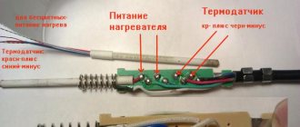
I myself took a Ya Xun soldering iron for stations of this type, 40 watts with a durable tip. The plug has 5 pins (contact holes), the pinout of the plug is below
Please note that the photo shows the pinout of the plug on the soldering iron itself.
The soldering iron has a built-in thermocouple, the data from which is received and decrypted by the station itself. You MUST need a soldering iron with a thermocouple, and not with a thermistor as a temperature sensor.
The thermocouple has polarity; if the thermocouple is connected incorrectly, the soldering iron will reach its maximum temperature after turning on and become uncontrollable.
Hairdryer
In principle, the power can be from 350 to 700 watts, I advise no more than 400 watts,
That's enough for any needs. The hair dryer also has a built-in thermocouple as a temperature sensor. The hair dryer must have a built-in cooler. It has an 8-pin socket, the pinout of the socket on the hair dryer is presented below.
Inside the hair dryer there is a 220 Volt heater itself, a thermocouple, a fan and a reed switch, the latter can be immediately thrown away; it is not needed in this project.
The heater does not have polarity, but the thermocouple and cooler do, so be sure to observe the polarity of the connection, otherwise the motor will not spin, and the heater will reach its maximum temperature and become uncontrollable.
power unit
Any (preferably stabilized adapter) 24 Volts minimum 2 Amperes, I advise 4-5 Amps. Universal chargers for laptops are perfect, they have the ability to adjust the output voltage from 12 to 24 Volts, protection against short circuits and a stabilized output - and it costs a penny, I chose this one myself.
You can also use a low-power power supply for 24 Volt LED strips, available with a current of 1 Ampere.
You can also slightly modify the electronic transformer (as the most budget option) and implement it into the circuit; I explained in more detail about power supplies at the end of the video (part 1)
You can also use a transformer power supply - it may not be stabilized, but I repeat - it is desirable to have stabilization.
Installation and housing
The case is from a Chinese radio, the 16x2 display fits perfectly with it, all controls are installed on a separate plastic sheet and docked to the bottom of the radio.
The main power components are reinforced to the heat sink through additional insulating gaskets and plastic washers. The heat sink was taken from a non-working uninterruptible power supply.
It heats up, but only after working for a long time with a hairdryer at high power, but all this is tolerable, by the way - the board provides an additional 12 Volt output for connecting a Cooper, so that you can blow off the radiator if there is a need for it.
Settings
In principle, to set up you need either a thermometer or a tester with a thermocouple and the ability to measure temperature.
First, you need to set a certain temperature on the soldering iron (for example, 400 degrees), then press the thermocouple to the soldering iron tip to understand the real temperature on the soldering iron tip, and then simply using a trimmer resistor on the board (slow rotation) we achieve to compare the real temperature on the soldering iron (which is displayed) with the one shown by the thermometer.
The same thing needs to be done with a hairdryer, only the thermometer needs to be placed under a stream of hot air.
I highly recommend that you take multi-turn trimmer resistors for convenient and precise adjustment.
By the way, the third trimmer on the board is responsible for the display contrast.
Minuses
To be honest, I didn’t notice, the design is universal, convenient, simple, and at the same time we get a professional soldering station for any needs, for which great respect goes to the author.
Main advantages and costs.
The price category of such stations is around 100 - 150 $, we have full control of a hair dryer and soldering iron and a fairly smart filling that displays all the data on an LCD display; in budget stations, instead of a display, there are ordinary LED indicators.
Smart control system for the hot air gun - when you turn off the hair dryer itself, the cooler will work until the heater cools down, then it will turn off by itself, also a very thoughtful safety solution, which is available on all profs. stations.
It is also possible to adjust the cooler speed.
Both in the case of a hair dryer and in the case of a soldering iron, the maximum temperature is 480 degrees.
On account of costs
- You can buy a soldering iron here
- Hairdryer here
- Hair dryer attachments here
- Arduino board with MK here
- LCD display here
- A set of soldering iron tips is here
- Power supply here
PS this article was published in half an hour, if I missed anything, forgive me.
PCB installation
When assembling a printed circuit board, it is convenient to use the assembly drawing:
Assembly drawing of the printed circuit board of the Simple Solder MK936 soldering station
The installation process will be shown and commented on in detail in the video below. Let us note only a few points. It is necessary to observe the polarity of electrolytic capacitors, LEDs and the direction of installation of microcircuits. Do not install microcircuits until the case is completely assembled and the supply voltage has been checked. ICs and transistors must be handled carefully to avoid damage from static electricity.
Once the board is assembled, it should look like this:
Soldering station printed circuit board assembly
Contactless soldering iron
If there is no urgent need to use an infrared soldering station, then an infrared soldering iron can be successfully used for soldering. Outwardly, it is similar to a regular one, with the difference that instead of a sting it has a heating element.
Application and device
An infrared soldering iron is used in conditions where contact with component leads is unacceptable. It is also convenient to use it for soldering radio components, since often with a regular soldering iron carbon deposits form on the tip and the connections are of poor quality. The carbon deposits have to be cleaned off, and these actions sometimes take quite a lot of time.
In a home workshop, you can make a simple homemade infrared soldering iron from a car cigarette lighter. The heating element of this device is perfect for making tools.
Since normal operation of the cigarette lighter requires a direct current of 12 Volts, corresponding to the on-board electrical network of the car, you will need an electrical converter so that you can use a household AC network. For these purposes, you can successfully use a power supply for computer cases.
Housing assembly and volumetric installation
The block wiring diagram looks like this:
Soldering station wiring diagram
That is, all that remains is to supply power to the board and connect the soldering iron connector. You need to solder five wires to the soldering iron connector. The first and fifth are red, the rest are black. You must immediately put a heat-shrinkable tube on the contacts, and tin the free ends of the wires. The short (from the switch to the board) and long (from the switch to the power source) red wires should be soldered to the power switch. The switch and connector can then be installed on the front panel. Please note that the switch may be very difficult to engage. If necessary, modify the front panel with a file!
Connecting the soldering iron connector
Next, you need to tighten the left and rear walls of the case with screws. Remember that plexiglass is a fragile material, and do not overtighten the threaded connections!
Assembling the soldering station housing
The next step is to put all these parts together. There is no need to install the controller, operational amplifier or screw on the front panel!
Assembling the soldering station housing
Parts for a homemade device
Commercially available infrared soldering stations of domestic and foreign production are very widely available on sale, but their prices start from 20,000 rubles.
And at the minimum price, it will not be a tool of the best quality. If you need to work with BGA packages in conditions of limited funds, a homemade infrared soldering station can be a solution.
It can be assembled from parts of infrared stations available for sale, as well as from scrap materials and old devices that have expired.
A heat table for a soldering station can be made from a lamp or heater with halogen lamps, which will heat the board to the required temperature. The top heater and soldering station controller will have to be purchased from spare parts, buying them new or used.
A tripod for the upper heating block can be made from the support of an old table lamp.
For the heating table, you need to stock up on halogen lamps and reflectors. They are placed in a housing that can be made independently from aluminum profiles and sheet metal.
In addition to the lamps, it is necessary to provide a place in the housing for attaching a thermocouple, which will “supply” information about the temperature of the lamps to the control module.
The temperature must be maintained precisely so that the boards do not crack from excess heat and sudden temperature changes.
Controller firmware and setup
You can find the HEX file for the controller firmware at the end of the article. The fuse bits should remain factory, that is, the controller will operate at a frequency of 1 MHz from the internal oscillator. The first power-up should be done before installing the microcontroller and operational amplifier on the board. Apply a constant supply voltage from 12 to 24V (red should be “+”, black “-“) to the circuit and check that there is a 5V supply voltage between pins 2 and 3 of the DA1 stabilizer (middle and right pins). After this, turn off the power and install the DA1 and DD1 chips into the sockets. At the same time, monitor the position of the chip key. Turn the soldering station back on and make sure all functions are working correctly. The indicator displays the temperature, the encoder changes it, the soldering iron heats up, and the LED signals the operating mode. Next, you need to calibrate the soldering station. The best option for calibration is to use an additional thermocouple. It is necessary to set the required temperature and control it on the tip using a reference device. If the readings differ, then adjust the multi-turn trimmer resistor R4. When setting, remember that the indicator readings may differ slightly from the actual temperature. That is, if you set, for example, the temperature to “280”, and the indicator readings deviate slightly, then according to the reference device you need to achieve exactly a temperature of 280°C. If you don’t have a control measuring device at hand, you can set the resistor resistance to about 90 kOhm and then select the temperature experimentally. After the soldering station has been checked, you can carefully install the front panel so that the parts do not crack.
Soldering station assembly
Soldering station assembly
Purpose and objectives of application
Soldering stations are used in radio engineering and related areas of production and creativity. Users use the tool to perform different types of work.
- Pyrography is the making of drawings using thermal devices. By heating individual sections of the workpieces, the position of the thermoplastic elements is changed. Compositions are created from plastics of one color or multi-color compositions.
- Weld plastics in the manufacture of cases, boxes or other flat and spatial products.
- Carrying out installation, repairs and other targeted work. Some types of work are only possible with the use of hair dryers that melt plastic particles without overheating it.
- For assembling electronic devices and instruments.
- Soldering and installation of electronic circuits in electronics.
- Tinning and preparation for complex installation of massive parts and assemblies connected by melting solder.
- For welding in confined spaces.
- Soldering SMD components, mounting and dismantling them on boards.
- For shrinking heat-shrinkable insulation upon completion of work.
UPD
The files posted above are outdated. In the current version, we have updated the drawings for cutting plexiglass, making a printed circuit board, and also updated the firmware to remove the flickering indicator. Please note that the new firmware version requires CKSEL0, CKSEL2, CKSEL3, SUT0, BOOTSZ0, BOOTSZ1 and SPIEN to be enabled
(that is, change the default settings). Printed circuit board in Sprint Layout V1.1 format Firmware for microcontroller V1.1 File for cutting plexiglass V1.1
This soldering station can also be purchased as a kit for self-assembly in our store and from our partners GOOD-KITS.ru and ROBOTCLASS.ru.
Assembly
An infrared head with a power of about 400-450 W must be mounted on a tripod using fasteners, the elements of which can be easily purchased in a retail chain; to control the temperature of the upper heating unit, a second thermocouple must be used.
It must be installed together with the heater. The cable can be laid in a flexible metal hose. The soldering station tripod must be mounted in such a way that the IR head can move freely over the entire surface.
It is necessary to provide brackets for fixing the board on the body of the thermal table. It should be located a few centimeters above halogen lamps. Suitable aluminum profiles can be used for the brackets.
The controller for the infrared soldering station is placed in a housing that can be made independently from sheet metal, preferably galvanized steel.
If necessary, you can build into the case the same cooling fans that are used in the computer case.
After assembling the structure itself, the entire circuit of the infrared soldering station will need to be debugged. This is done experimentally by repeatedly running the circuit and taking measurements. The process is not easy, but after setting it up it will give its results - the soldering station will work correctly.