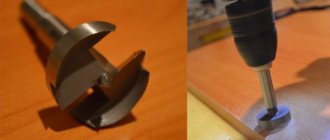
To fully work with a hand router, in addition to the tool itself, the material and the corresponding set of cutters, you need to have one more component - fixtures. In order for the cutter to be able to shape the workpiece in accordance with the master's plan - cutting the material exactly where it is required - it must be in a strictly defined position relative to the workpiece at each moment of time. Numerous accessories for a hand router are used to ensure this. Some of them - the most necessary ones - are included in the delivery package of the tool. Other devices for milling can be purchased or made by yourself. Moreover, homemade devices are so simple that to make them you can do without drawings, using only their drawings.
Rip fence
To install the device in the working position, it is necessary to slide the rods 2 into the holes of the frame 3, ensuring the required distance between the supporting surface of the stop and the axis of the cutter, and fix them with the locking screw 4. To accurately position the cutter, you need to release the locking screw 9 and rotate the fine adjustment screw 5 set the cutter to the desired position. For some stop models, the dimensions of the supporting surface can be changed by moving or spreading the support pads 8.
If you add one simple part to the rip fence, then you can use it to mill not only straight, but also curved grooves, for example, to process a round workpiece. Moreover, the inner surface of the block located between the stop and the workpiece does not necessarily have to have a rounded shape that follows the edge of the workpiece. It can also be given a simpler shape (Figure “a”). In this case, the trajectory of the cutter will not change.
Of course, a regular rip fence, thanks to the notch in the center, will allow you to orient the router along a rounded edge, but the position of the router may not be stable enough.
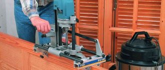
Guide rail
The guide rail is attached to the table or workpiece using clamps or special clamps. The tire can be equipped with an adapter (shoe), which is connected to the base of the router by two rods. Sliding along the profile of the tire, the adapter sets the linear movement of the cutter.
Sometimes (if the distance of the tire from the router is too close), the supporting surfaces of the tire and the router may appear in different planes in height. To level them, some routers are equipped with retractable support legs, which change the position of the router in height.
Such a device is easy to make with your own hands. The simplest option is a long block secured to the workpiece with clamps. The design can be supplemented with side supports.
By placing a block on two or more aligned workpieces at once, grooves can be made in them in one pass.
When using a block as a stop, it is inconvenient to place the block at a certain distance from the line of the future groove. The following two devices do not have this inconvenience. The first is made from boards and plywood fastened together. In this case, the distance from the edge of the stop (board) to the edge of the base (plywood) is equal to the distance from the cutter to the edge of the router base. But this condition is met only for a cutter of the same diameter. Thanks to this, the device quickly aligns along the edge of the future groove.
The following device can be used with cutters of different diameters, plus when milling, the router rests on its entire sole, and not half, as in the previous device.
The stop is aligned along the edge of the hinged board and the center line of the groove. After fixing the stop, the folding board folds back, making room for the router. The width of the folding board, together with the gap between it and the stop (if there is one), should be equal to the distance from the center of the cutter to the edge of the router base. If you focus on the edge of the cutter and the edge of the future groove, then the device will only work with one diameter of the cutter.
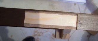
When milling grooves across the grain, at the exit from the workpiece, when milling an open groove, cases of wood scuffing are not uncommon. The following devices will help to minimize scuffing: I press the fibers where the cutter exits, preventing them from splitting off from the workpiece.
Two boards, strictly perpendicular, are connected with screws. Different cutters are used on different sides of the stop so that the width of the groove in the fixture matches the width of the groove of the part being milled.
Another attachment for routing open slots can be pressed harder against the workpiece, which further minimizes scuffing, but it only fits one diameter cutter. It consists of two L-shaped parts connected to the workpiece with clamps.
Copy rings and templates
The diameter of the copy ring should be as close to the diameter of the cutter as possible, but the ring should not touch its cutting parts. If the diameter of the ring is larger than the diameter of the cutter, then the template must be smaller than the finished parts to compensate for the difference between the diameter of the cutter and the diameter of the copy ring.
Read also: Heel grinder
The template is secured to the workpiece with double-sided tape, then both parts are pressed with clamps to the workbench. Once you have finished routing, check that the ring is pressed against the edge of the template throughout the entire operation.
You can make a template for processing not the entire edge, but only for rounding the corners. In this case, using the template shown below, you can make roundings of four different radii.
In the figure above, a cutter with a bearing is used, but the template can also be used with a ring, only either the ring must exactly match the diameter of the cutter, or the stops must make it possible to move the template away from the edge by the difference in the radius of the cutter and the ring. This also applies to the simpler version shown below.
Templates are used not only for milling edges, but also grooves on the face.
The template can be adjustable.
Template routing is a great method for cutting out hinge grooves.
Tools for milling round and elliptical grooves
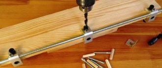
It is better, of course, for the compass to be made of two rods.
In general, compasses are a very common device. There are a large number of branded and homemade devices for circumferential milling, varying in size and ease of use. As a rule, compasses have a mechanism that ensures a change in the radius of the circle. It is usually made in the form of a screw with a pin at the end, moving along the groove of the device. The pin is inserted into the central hole of the part.
When it is necessary to mill a circle of small diameter, the pin must be located under the router base, and for such cases, other devices are used that are attached to the bottom of the router base.
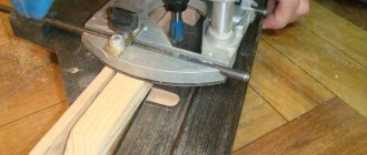
Ensuring the movement of the cutter in a circle using a compass is quite simple. However, one often has to deal with the need to make elliptical contours - when inserting oval-shaped mirrors or glass, installing arched windows or doors, etc. The PE60 WEGOMA device (Germany) is designed for milling ellipses and circles.
It is a base in the form of a plate, attached to the surface using vacuum suction cups 1 or with screws if the nature of the surface does not allow it to be fixed using suction cups. Two shoes 2, moving along intersecting guides, ensure the movement of the milling cutter along an elliptical path. When milling a circle, only one shoe is used. The device kit includes two mounting rods and bracket 3, with the help of which the router is connected to the slab. The grooves on the bracket allow you to install the router so that its supporting surface and the base of the slab are in the same plane.
As can be seen from the photographs above, a router was used instead of a jigsaw or band saw, and due to the high speed of the cutter, the quality of the processed surface was much higher. Also, if you don’t have a hand-held circular saw, a router can replace it.
Devices for milling grooves on narrow surfaces
To make grooves in the end, you can make a simple device in the form of a flat base attached to the base of the router. Its shape can be not only round (according to the shape of the base of the router), but also rectangular. On both sides you need to secure guide pins that will ensure the straight movement of the router. The main condition for their installation is that their axes are in line with the center of the cutter. If this condition is ensured, the groove will be located exactly in the center of the workpiece, regardless of its thickness. If you need to move the groove to one side or another from the center, you need to put a bushing with a certain wall thickness on one of the pins, as a result of which the groove will move to the side on which the pin with the bushing is located. When using a router with such a device, it must be guided in such a way that the pins are pressed on both sides to the side surfaces of the part.
If you attach a second rip fence to the router, you will also get a device for milling grooves in the edge.
But you can do without special devices. To ensure stability of the router on a narrow surface, boards are secured on both sides of the part, the surface of which should form a single plane with the surface being processed. When milling, the router is positioned using a rip fence.
You can make an improved version that increases the support area for the router.
Device for processing balusters, pillars and other bodies of rotation
Sometimes there is a need to mill various grooves in rotating bodies. In this case, the device shown below may be useful.
The device is used for milling longitudinal grooves (flutes) on balusters, posts, etc. It consists of a body 2, a movable carriage with an installed milling cutter 1, a disk for setting the angle of rotation 3. The device operates as follows. The baluster is placed in the body and secured there with screws 4. Rotation to the desired angle and fixation of the workpiece in a strictly defined position is ensured by disk 3 and locking screw 5. After fixing the part, the carriage with the router is set in motion (along the guide bars of the body), and the milling a groove along the length of the workpiece. Then the product is unlocked, rotated to the required angle, locked, and the next groove is made.
Read also: Many sockets in one, what is it called?
A similar device can be used instead of a lathe. The workpiece should be rotated slowly by an assistant or a simple drive, for example, from a drill or screwdriver, and excess material should be removed by a milling cutter moving along the guides.
Tools for milling tenons
The figure below shows an industrial sample of a tenon-cutting device for the manufacture of three types of joints - a dovetail (blind and through version) and a through joint with a straight tenon. The two mating parts are installed in the fixture with a certain shift relative to each other, controlled by pins 1 and 2, then they are processed. The exact trajectory of the cutter is determined by the shape of the groove in the template and the copying ring of the router, which slides along the edge of the template, repeating its shape.
Nowadays it is very difficult to imagine any plumbing activity without the use of a router. But not so long ago, people made grooves, made three-dimensional figures using a plane, chisel and hacksaw. In modern times, various milling devices, including those made independently, are becoming increasingly popular. Do-it-yourself templates for a router make it easier to control the mechanism and help process surfaces as accurately and accurately as possible.
Diagram of a rip fence on a manual router.
Such a device is necessary where you need to make a hole, smooth the edge of a product, or cut out a three-dimensional shape. Milling is used when cutting out ornaments, patterns, and preparing niches for installing corners, locking mechanisms, and hinges. This tool allows you to remove a chamfer and round the edge of any part. According to its characteristics, the router resembles the actions of a plane.
This processing device works with wood, plastic and aluminum. However, each case requires the installation of specified speed limits and appropriate equipment. Despite the active use of a router, such attributes of construction significance as a chisel, hacksaw, and cutter are still used in work. The use of templates for these installations is often associated with furniture making.
Making a homemade furniture template
The correct direction when working with a router.
Any employee of a furniture organization knows perfectly well how difficult it is to make a corner kitchen. Installing the countertop requires precise joints, rounding the leading edge and flattening other parts. It is known that a flat edge, placed in the form of a rounded beginning, will acquire an unattractive appearance with a noticeable rough seam. To ensure that the cutting is carried out correctly and accurately, a milling device and a specially made template for furniture are used. Creating such samples yourself is not so difficult.
The main devices, without which installation will be impossible, will be:
- fiberboard sheet;
- manual milling mechanism;
- blueprints.
Step-by-step production of a template for furniture
Furniture parts cut according to a template have the same shape and size.
- Such a template, made by yourself, will perform its functions no worse than one purchased in a store. To create it, you need to prepare a drawing and a cover for the processing machine. Then a test homemade product is made from a fiberboard sheet; its thickness is equal to 8 mm.
- Next, the diameter of the cutter and the machine itself is measured. Then 2 intersecting lines are drawn, the angle of which is 135°. To smooth out these indicators, an arc is taken. To calculate its radius, you should find out similar readings for the cutter and rings. The resulting difference in the radii of the rings and cutters should be subtracted from the value of the first device.
- This creates an internal arc. The flat end of the postforming is milled along its base. As the ring moves along a given radius, the cutter describes an arc whose diameter is equal to its own.
- From the drawn segment, 2 lines are laid parallel to each other. The distance between these points is equal to the diameter of the ring of the router used. 5 mm is added to these readings. The line starts from the middle of the previous arc.
- The connection point of the segments is smoothed using an arc. Its radius corresponds to similar readings of the device’s thrust ring. During movement, the cutter will no longer be able to perform arcuate movements.
- You need to draw 2 equal rectangles that imitate the contours of the tabletop. An angle is applied to them, after which it is extended to a certain distance.
- Marking the template will make your work much easier. The arcs of the top and bottom rows will not overlap. Therefore, it is necessary to carry out verification for each detail by slightly shifting these boundaries.
Rules for working with templates for a router.
Templates for a hand router
- The first step is to make a template from hardboard, the thickness of which is 6 mm. The height of the MDF stencil is 12 mm. These materials are very easy to process and are in no way inferior to wood. However, their corners easily bend from accidental impacts or falls. In order for the templates to serve for a long time, it is necessary to take high quality birch. Despite its high cost, unlike MDF, it has greater strength and consistency of characteristics.
Edge routing using a template and a copy ring.
The boundaries of the parts are drawn on the surface of the template in compliance with natural proportions. Then the starting grooves are drilled, the unnecessary material is cut with a jigsaw, keeping an indent of 1 mm near the contour line. The edges of the edge are carefully sanded, the paper stencil is removed.
- Using a template, a specified number of parts are created. Then this element is placed on the product and outlined with a pencil. Unnecessary material is cut out, moving 1.5 mm away from the contour. Similar actions are carried out with other workpieces.
- Using fabric-based double-sided tape, the template is fixed to one of the products. In order for the work to proceed as quickly as possible, you should insert a cutter with a bearing on the shank into the machine collet. This part rolls along the edge of the stencil.
- Then you need to select the type of cutter. All varieties with bearings are used for milling according to templates; the device is held in the hand and installed on the surface. Using a copying cutter, the operation of the machine is monitored at the moment when the part moves along the table, the template is located on top.
- The space between the tip and the shank does not need to be machined with a bearing cutter in one pass. This can be done in 2-3 times using a cheaper version of the cutter. Milling is carried out by aligning the bearing with the middle part of the stencil thickness.
- A thrust rod device is placed close to the cutter. The machine turns on, the part is pressed against this part and gradually moves towards the rotating cutter until the bearing comes into contact with the template. Milling of external contours is carried out counterclockwise, internal contours - in the opposite direction. At the moment the cutter bearing comes into contact with the template, the part is removed from the rod stop device.
Read also: Caring for a spray foam gun
The copying device at the shank functions similarly, however, it is necessary to rotate the part so that the stencil faces the table surface. Milling is carried out similarly to the operation of a milling table. During the manipulation process, it is important to monitor the integrity of the base of the workbench.
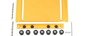
Milling accessories
Parallel stop Guide rail Copy rings and templates Devices for milling rounded grooves Milling grooves on narrow surfaces Device for processing bodies of rotation Devices for milling tenons To fully work with a hand router, in addition to the tool itself, the material and the corresponding set of cutters, you must have one more component - devices. In order for the cutter to be able to shape the workpiece in accordance with the master's plan - cutting the material exactly where it is required - it must be in a strictly defined position relative to the workpiece at every moment of time. Numerous accessories for a hand router are used to ensure this. Some of them - the most necessary ones - are included in the delivery package of the tool. Other devices for milling can be purchased or made by yourself. Moreover, homemade devices are so simple that to make them you can do without drawings, using only their drawings.
Rip fence
The most used device that comes with almost every router is a parallel stop, which ensures the straight movement of the cutter relative to the base surface. The latter can be the straight edge of a part, table or guide rail. The parallel stop can be used both for milling various grooves located on the face of the workpiece, and for processing edges.
Parallel stop for a manual router: 1 - stop, 2 - rod, 3 - base of the router, 4 - rod locking screw, 5 - fine adjustment screw, 6 - movable carriage, 7 - movable carriage locking screw, 8 - pads, 9 - screw stop locking.
Edge routing using the rip fence
To install the device in the working position, it is necessary to slide the rods 2 into the holes of the frame 3, ensuring the required distance between the supporting surface of the stop and the axis of the cutter, and fix them with the locking screw 4. To accurately position the cutter, you need to release the locking screw 9 and rotate the fine adjustment screw 5 set the cutter to the desired position. For some stop models, the dimensions of the supporting surface can be changed by moving or spreading the support pads 8.
If you add one simple part to the rip fence, then you can use it to mill not only straight, but also curved grooves, for example, to process a round workpiece. Moreover, the inner surface of the block located between the stop and the workpiece does not necessarily have to have a rounded shape that follows the edge of the workpiece. It can also be given a simpler shape (Figure “a”). In this case, the trajectory of the cutter will not change.
Stop for milling round surfaces
Of course, a regular rip fence, thanks to the notch in the center, will allow you to orient the router along a rounded edge, but the position of the router may not be stable enough.
Guide rail
The function of the guide bar is similar to that of a rip fence. Like the latter, it ensures strictly linear movement of the router. The main difference between them is that the tire can be installed at any angle to the edge of the part or table, thereby ensuring any direction of movement of the router in the horizontal plane. In addition, the tire may have elements that simplify certain operations, for example, milling holes located at the same distance from each other (with a certain pitch), etc.
Guide rail
The guide rail is attached to the table or workpiece using clamps or special clamps. The tire can be equipped with an adapter (shoe), which is connected to the base of the router by two rods. Sliding along the profile of the tire, the adapter sets the linear movement of the cutter.
Sometimes (if the distance of the tire from the router is too close), the supporting surfaces of the tire and the router may appear in different planes in height. To level them, some routers are equipped with retractable support legs, which change the position of the router in height.
Such a device is easy to make with your own hands. The simplest option is a long block secured to the workpiece with clamps. The design can be supplemented with side supports.
Simple stop
By placing a block on two or more aligned workpieces at once, grooves can be made in them in one pass.
Milling grooves on two workpieces at once
When using a block as a stop, it is inconvenient to place the block at a certain distance from the line of the future groove. The following two devices do not have this inconvenience. The first is made from boards and plywood fastened together. In this case, the distance from the edge of the stop (board) to the edge of the base (plywood) is equal to the distance from the cutter to the edge of the router base. But this condition is met only for a cutter of the same diameter. Thanks to this, the device quickly aligns along the edge of the future groove.
Slot milling fixture
The following device can be used with cutters of different diameters, plus when milling, the router rests on its entire sole, and not half, as in the previous device.
Slot milling fixture
Slot milling attachment
The stop is aligned along the edge of the hinged board and the center line of the groove. After fixing the stop, the folding board folds back, making room for the router. The width of the folding board, together with the gap between it and the stop (if there is one), should be equal to the distance from the center of the cutter to the edge of the router base. If you focus on the edge of the cutter and the edge of the future groove, then the device will only work with one diameter of the cutter.
When milling grooves across the grain, at the exit from the workpiece, when milling an open groove, cases of wood scuffing are not uncommon. The following devices will help to minimize scuffing: I press the fibers where the cutter exits, preventing them from splitting off from the workpiece.
T-stop
T-stop
Two boards, strictly perpendicular, are connected with screws. Different cutters are used on different sides of the stop so that the width of the groove in the fixture matches the width of the groove of the part being milled.
Another attachment for routing open slots can be pressed harder against the workpiece, which further minimizes scuffing, but it only fits one diameter cutter. It consists of two L-shaped parts connected to the workpiece with clamps.
Slot milling attachment
Slot milling attachment
Copy rings and templates
The copying ring is a round plate with a protruding shoulder that slides along the template and provides the necessary trajectory of the cutter. The copying ring is attached to the base of the router in various ways: they screw it into a threaded hole (such rings are in the photo below), insert the antennae of the ring into special holes on the base, or screw it with screws.
Copy rings
Installing the copy ring
The diameter of the copy ring should be as close to the diameter of the cutter as possible, but the ring should not touch its cutting parts. If the diameter of the ring is larger than the diameter of the cutter, then the template must be smaller than the finished parts to compensate for the difference between the diameter of the cutter and the diameter of the copy ring.
Routing an edge using a template and a copy ring
The template is secured to the workpiece with double-sided tape, then both parts are pressed with clamps to the workbench. Once you have finished routing, check that the ring is pressed against the edge of the template throughout the entire operation.
You can make a template for processing not the entire edge, but only for rounding the corners. In this case, using the template shown below, you can make roundings of four different radii.
First you need to saw off the corner
Rounding a corner using a template
In the figure above, a cutter with a bearing is used, but the template can also be used with a ring, only either the ring must exactly match the diameter of the cutter, or the stops must make it possible to move the template away from the edge by the difference in the radius of the cutter and the ring. This also applies to the simpler version shown below.
Template for rounding corners
Rounding a corner using a template
Templates are used not only for milling edges, but also grooves on the face.
Milling a groove using a template
The template can be adjustable.
Adjustable pattern
Milling a groove using a template
Template routing is a great method for cutting out hinge grooves.
Template for milling grooves for hinges
Milling grooves for hinges
Tools for milling round and elliptical grooves
Compasses are designed to move the router around a circle.
The simplest device of this type is a compass, consisting of one rod, one end of which is connected to the base of the router, and the second has a screw with a pin at the end, which is inserted into a hole that serves as the center of the circle along which the cutter moves. The radius of the circle is set by shifting the rod relative to the base of the router. Circle milling attachment
It is better, of course, for the compass to be made of two rods.
Circle milling attachment
In general, compasses are a very common device. There are a large number of branded and homemade devices for circumferential milling, varying in size and ease of use. As a rule, compasses have a mechanism that ensures a change in the radius of the circle. It is usually made in the form of a screw with a pin at the end, moving along the groove of the device. The pin is inserted into the central hole of the part.
Circle milling attachment
Circle milling attachment
Circle milling attachment
When it is necessary to mill a circle of small diameter, the pin must be located under the router base, and for such cases, other devices are used that are attached to the bottom of the router base.
Device for milling small diameter circles
Ensuring the movement of the cutter in a circle using a compass is quite simple. However, one often has to deal with the need to make elliptical contours - when inserting oval-shaped mirrors or glass, installing arched windows or doors, etc. The PE60 WEGOMA device (Germany) is designed for milling ellipses and circles.
Device for milling circles and ellipses
Device for milling circles and ellipses
It is a base in the form of a plate, attached to the surface using vacuum suction cups 1 or with screws if the nature of the surface does not allow it to be fixed using suction cups. Two shoes 2, moving along intersecting guides, ensure the movement of the milling cutter along an elliptical path. When milling a circle, only one shoe is used. The device kit includes two mounting rods and bracket 3, with the help of which the router is connected to the slab. The grooves on the bracket allow you to install the router so that its supporting surface and the base of the slab are in the same plane.
As can be seen from the photographs above, a router was used instead of a jigsaw or band saw, and due to the high speed of the cutter, the quality of the processed surface was much higher. Also, if you don’t have a hand-held circular saw, a router can replace it.
Devices for milling grooves on narrow surfaces
Grooves for locks and door hinges, in the absence of a router, are made using a chisel and an electric drill.
This operation - especially when making a groove for an internal lock - takes a lot of time. Having a milling cutter and a special device, it can be completed several times faster. It is convenient to have a device that provides milling of slots in a wide range of sizes. To make grooves in the end, you can make a simple device in the form of a flat base attached to the base of the router. Its shape can be not only round (according to the shape of the base of the router), but also rectangular. On both sides you need to secure guide pins that will ensure the straight movement of the router. The main condition for their installation is that their axes are in line with the center of the cutter. If this condition is ensured, the groove will be located exactly in the center of the workpiece, regardless of its thickness. If you need to move the groove to one side or another from the center, you need to put a bushing with a certain wall thickness on one of the pins, as a result of which the groove will move to the side on which the pin with the bushing is located. When using a router with such a device, it must be guided in such a way that the pins are pressed on both sides to the side surfaces of the part.
Device for milling grooves in edges
If you attach a second rip fence to the router, you will also get a device for milling grooves in the edge.
Device for milling grooves in edges
But you can do without special devices. To ensure stability of the router on a narrow surface, boards are secured on both sides of the part, the surface of which should form a single plane with the surface being processed. When milling, the router is positioned using a rip fence.
Device for milling grooves in edges
You can make an improved version that increases the support area for the router.
Device for milling grooves in edges
Milling a groove in a narrow surface
Device for processing balusters, pillars and other bodies of rotation
The variety of work that is performed with a manual milling cutter sometimes dictates the need to independently manufacture devices that facilitate the performance of certain operations.
Branded devices are not able to cover the entire range of work, and they are quite expensive. Therefore, home-made devices for a router are very common among users who are interested in working with wood, and sometimes hand-made devices are either superior to branded analogues or have no branded analogues at all. Sometimes there is a need to mill various grooves in rotating bodies. In this case, the device shown below may be useful.
Device for milling grooves on balusters
Device for milling grooves on balusters
Rotation angle dial
Router carriage
The device is used for milling longitudinal grooves (flutes) on balusters, posts, etc. It consists of a body 2, a movable carriage with an installed milling cutter 1, a disk for setting the angle of rotation 3. The device operates as follows. The baluster is placed in the body and secured there with screws 4. Rotation to the desired angle and fixation of the workpiece in a strictly defined position is ensured by disk 3 and locking screw 5. After fixing the part, the carriage with the router is set in motion (along the guide bars of the body), and the milling a groove along the length of the workpiece. Then the product is unlocked, rotated to the required angle, locked, and the next groove is made.
A similar device can be used instead of a lathe. The workpiece should be rotated slowly by an assistant or a simple drive, for example, from a drill or screwdriver, and excess material should be removed by a milling cutter moving along the guides.
Tools for milling tenons
Tenoning jigs are used to mill the profile of tenon joints. The manufacture of the latter requires great precision, which is almost impossible to achieve manually. Tenoning jigs allow you to quickly and easily profile even complex joints such as dovetails.
Tenon joints
The figure below shows an industrial sample of a tenon-cutting device for making three types of joints - a dovetail (blind and through version) and a through joint with a straight tenon. The two mating parts are installed in the fixture with a certain shift relative to each other, controlled by pins 1 and 2, then they are processed. The exact trajectory of the cutter is determined by the shape of the groove in the template and the copying ring of the router, which slides along the edge of the template, repeating its shape.
Tenon milling device
Milling tenons
Milling tenons
Milling tenons
When using the content of this site, you need to put active links to this site, visible to users and search robots.
Literature
Wedge templates for hand router
Template for rounding corners.
You can make a template in the form of spikes or wedges on your own. This compound is elegant and is most often used in furniture production. And there, as you know, high build quality is required. Using such primitive devices as a saw and a chisel in work, one cannot do without some experience in the construction industry, which cannot be said about a hand router. It allows even beginners to carry out the given work.
How to connect templates for a router so that it clearly marks the wedges on all workpieces? To do this, you can use a manual machine with decent characteristics. The ring must be the right size for the machine, otherwise it must be purchased.
A partially hidden wedge-shaped device can be seen on one side. The end-to-end connection can be traced from both points. To combine the two parts, the light element is installed strictly vertically. Periodically, the interdental space of the template is cleaned of sawdust. Upon completion of the work, existing roughness must be treated with emery cloth.
Making a device for picking out a tenon
When parts are processed manually, the milling cutter itself does not have additional spatial fixation. But the overall result of the work and the accuracy of the connection itself in the future depend on this.
To assemble the simplest design that can cope with the task, you will need to use:
- Several guides that remain stationary. They should be side and top or bottom.
- The length of the sample is adjusted through the use of an appropriate movable bar.
For manufacturing, the following sequence of actions is used:
- A plywood sheet is taken, from one edge of which the side elements are mounted in a vertical plane. It is necessary to create appropriate cutouts in the center of the material.
- The sides are equipped with guides. The base of the hand cutter moves along them later.
- The side strips are fixed on the upper guides. Then the movement of the working milling cutter associated with these parts becomes limited.
- The plywood sheet, which became the basis for the installation, also serves as a surface for installing the moving element. Then the amount of edge overhang for the future workpiece is easier to control under any circumstances. Fixation is ensured with ordinary screws and other types of fixing devices.
Key practical points
Milling a groove according to a template.
- Connecting parts.
Joints made using a hand router are installed to the full depth, which remains the same after the final fastening. Any of the copy rings moves into each recess. The template moves during the milling process of two elements. The displacement of parts should be as precise as possible, locking them with two support rods. So, with the help of a router, we were able to obtain the most accurate, somewhat hidden tenon joint. There is no need for additional gluing here. The parts are firmly attached to each other.
- Measuring and fixing templates.
The tenon mechanism is made of steel; the parts of this device are represented by two rods and screws. The glossy template helps to form a somewhat hidden wedge-shaped joint. It is easily replaced by a tenon alignment mechanism or a dovetail device. Then the depth of the copy ring is set. Further milling is associated with its movement along the teeth of the template.
Adjustable template details.
The dark-colored horizontal piece is tightly connected to the vertical element of a lighter tone, which is in line with the top bar.
- Adjustment of connecting elements.
To adjust the aligned points, the parts are brought to small rods that slightly move the base.
The template device moves to the lower part of the general mechanism, secured with a screw. Once the depth has been adjusted, milling can begin.
In this device it is possible to clamp elements whose width is 300 mm or less. The largest thickness values may differ by several mm.
- Templates for finger joints.
For such a device, the workpiece is placed in a vertical position and processed with a slot-type cutter. The spikes have smooth edges when they are parallel. To maintain the integrity of the part, a support device in the form of a block is installed at the time of milling.
- How to make templates for a router
- How to make a guitar
- How to make a machine
- – fibreboard;
- – manual milling machine;
- – drawing.
When making a template, pay attention to the fact that there is play between the support ring and the contours, so while milling, press the router to the desired contour.
It is best to mill in two passes at half the depth.
How are bodies of revolution processed?
The factory kit does not include a device for a router that allows you to cut grooves in cylindrical and conical workpieces. But home craftsmen have learned to make them themselves.
The product consists of the following parts:
- Cases.
- Movable milling carriage.
- Disk for adjusting the angle of rotation.
- Clamp for fastening the workpiece.
- Set screw.
The mechanism can be turned into a lathe by connecting an electric drill or screwdriver to it.