History of discovery
For the first time, the great metallurgist and inventor Dmitry Konstantinovich Chernov (1868) pointed out that there are certain (special) points in alloys (steels and cast irons).
It was he who made an important discovery about polymorphic transformations and is one of the creators of the iron-carbon phase diagram. According to Chernov, the position of these points on the diagram is directly dependent on the percentage of carbon content. And what is most interesting is that it is from the moment of this discovery that the science of metallography begins its life.
The diagram of iron-carbon alloys is the result of the painstaking work of scientists from several countries around the world. All letter designations of the main points and phases in the diagram are international.
Structures in an iron-carbon diagram
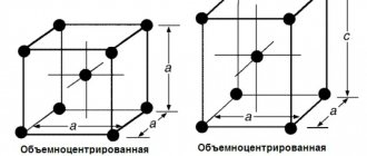
Let us recall the 2 crystalline forms of iron:
- α-iron. Has a body-centered cubic (bcc) lattice;
- γ-iron It has a face-centered cubic (fcc) lattice.
Crystal lattice of iron The polymorphic transformation of one form into another during heat treatment of steels occurs when the alloys pass through the GSK line.
Let us distinguish 4 phases in the iron-carbon system:
- Liquid phase. Carbon concentration is not limited;
- Ferrite is a solid solution of carbon in α-iron. The maximum carbon concentration is only 0.025% (point P). At room temperature – not higher than 0.006%. Ferrite is soft and ductile.
- Austenite is a solid solution of carbon in γ-iron. The maximum carbon concentration is 2.14% (point E). Austenite has low hardness, is plastic, and is not magnetic.
- Cementite is a chemical compound of iron and carbon (iron carbide, Fe3C). The carbon concentration is, accordingly, constant – 6.67% carbon. Cementite is very hard, brittle, and non-plastic.
Depending on the conditions of education, there are:
- primary cementite (formed from liquid);
- secondary cementite (precipitated from austenite around its grains);
- tertiary cementite (precipitated from ferrite along the boundaries of its grains);
- eutectoid cementite (is a component of pearlite);
- eutectic cementite (is a component of ledeburite).
It is also necessary to distinguish 2 structural components of iron-carbon alloys:
- Pearlite (eutectoid) is a mechanical mixture of 2 phases - plates/grains of ferrite and cementite. Pearlite is formed as a result of the pearlitic transformation of austenite (“free” or included in ledeburite) with a carbon concentration of 0.8% when passing below the PSK line:
A0.8→F0.025 + C6.67
Perlite structure. F - ferrite, C - cementite
In this case, iron passes from the γ-form to the α-form. Mechanical properties strongly depend on the size (dispersity) of the particles that make up a given pearlite.
- Ledeburite (eutectic) is a mechanical mixture of 2 phases – plates/grains of austenite and cementite. Ledeburite forms from a liquid phase with a carbon concentration of 4.3% when passing below the ECF line:
Zh4.3→A2.14 + C6.67
Structure of ledeburite. C - cementite, A - austenite.
Repeating, we recall that when alloys pass below the PSK line (727°C), austenite, which is part of ledeburite, undergoes a pearlite transformation, separating into ferrite and cementite. Ledeburite is hard and brittle.
At room temperature, iron-carbon alloys can have different structures, and therefore properties, although they always consist of only 2 phases: ferrite and cementite.
Component composition
The iron-carbon diagram was developed to show the microstructural state of a metal as a function of temperature and carbon content. It shows that, depending on the intensity of steel cooling, very different microstructures can appear in it.
When the metal is molten, that is, in a liquid state, there are no lattice structures. Atoms can move freely in all directions. To achieve the desired crystal structures, it is necessary to allow the metal to cool slowly and completely at room temperature. Intermediate heat treatments have a positive effect on the formation of crystalline structures.
Along the vertical axis of the iron-carbon diagram is the temperature scale in °C. The metal is shown here from solid to liquid state. For example, pure iron begins to melt at 1147°C. The temperature of the stable state of the melt is 1536 °C.
The horizontal axis indicates the percentage of carbon in the metal.
The lines that connect the characteristic points of the diagram mark the transformation of the metal. They separate areas where the metal is in a state of transformation from solid to liquid. But at the same time, the iron-carbon phase diagram also determines the reorganization of atoms in the crystal lattice.
The diagram shows areas where the metal is only in the state. melt, ferrite or austenite. The remaining zones are characterized by a certain combination of properties. These are, for example, melt and austenite, austenite and ferrite, ferrite and pearlite.
The designation of intersection points in capital letters on the transformation lines is intended for better understanding. They indicate a transition to another state or condition.
The diagram assumes constant cooling of metals. If the metal is cooled slowly, large grains are formed, but if the metal cools quickly, the grain sizes decrease. The type of metal grain determines its strength properties. Coarse-grained material has lower strength, but it can be made finer and therefore stronger by heat treatment or plastic deformation (hardening). Fine-grained metal has the highest level of strength.
Let us briefly characterize the main chemical components of the diagram.
Iron
Iron forms a cubic spatial lattice. The iron atoms are located at the corners of this lattice. The amount of carbon that can be dissolved in iron depends on the modification of the iron because different crystal lattice shapes of iron (e.g., space-centered cubic and face-centered cubic) have interstitial spaces of different sizes.
A minor role is played by the delta-mixed crystal, which has body-centered atoms, but exists only in high-alloy steels. These crystals form in the temperature range from 1536 °C (the melting point of pure iron) to 1392 °C.
An alpha mixed crystal exists as a body-centered cubic lattice. These structures form in pure iron up to a temperature of 911 °C.
In a gamma mixed crystal, the iron atoms are face-centered, meaning that they are located in the middle of each face of the cube. These crystals form at temperatures ranging from 1392 °C to 911 °C in pure iron.
Carbon
In low concentrations, carbon does not form a solid chemical compound with iron, but is deposited in the interstices of the iron crystal lattice.
Carbon in iron is an interstitial impurity and can exist in the form of a face-centered or body-centered cubic lattice. The phase diagram of iron-carbon alloys establishes regions of stable existence of a solid solution with α, γ and δ iron phases.
The crystal lattices described above have different carbon solubilities depending on temperature. Carbon is deposited in the interstitial spaces of the crystal lattice, while the face-centered cubic lattice, also called austenite, has a solubility no more than one hundred times higher than ferrite crystals.
Cementite
Cementite is a metastable phase of an alloy with a fixed composition, having the chemical formula Fe3C. At room temperature, cementite very slowly decomposes into iron and carbon (graphite).
Several other factors (such as high temperatures and the addition of certain alloying elements) may influence this decomposition as they promote the formation of graphite.
Cementite is hard and brittle, which makes it suitable for hardening steel (there is a special technology for chemical-thermal treatment of steel called cementation). The mechanical properties of cementite depend on its microstructure, as well as on the conditions of bonding with ferrite.
The liquid Fe-C solution on the diagram is indicated above the L (liquidus) line. Since δ-ferrite melts at 1538 °C, it is obvious that the melting point of iron decreases with increasing carbon content.
Perlite
Perlite grains include structural associations where all the formed plates are parallel to each other. As the number of pearlite nodules increases, the growth in the size of the plates stops, and they themselves can change the direction of their movement. As the temperature decreases, perlite colonies turn into spherical, fine-grained formations.
Ledeburite in steels
Ledeburite is one of the main structural components of iron-carbon alloys and is a eutectic mixture of austenite and cementite that forms at 1145°C and below (for pure iron-carbon alloys). Austenite transforms into a ferrite-cementite mixture at temperatures below 723°C. In steels, ledeburite, consisting of austenite and carbides, is formed only at a very high content of alloy components and carbon (0.7...1.0%); Such steels (called ledeburite steels.
Metastable unalloyed ledeburite eutectic Fe – Fe3C is classified as quasi-regular. It has been proven that after the nucleation of Fe3C, the growth of cementite plates occurs rapidly, resulting in the formation of austenite at the joints, and an orientation relationship occurs. Fe3C and austenite also grow together and form a rod structure that is perpendicular to the cementite plates. These two growth modes form a quasi-regular structure, but growth at the edge is faster than at the sides and dominates the structure. Experiments on directional crystallization showed that the operating point on the growth curve of a quasi-regular structure is close to the extremum point. Such a quasi-regular structure can be modified by quenching, but modification of impurities has not yet been studied.
The structural substrate of ledeburite class steels has hypoeutectic components, including pearlite, ledeburite and nodular graphite. The doped layer consists of dendrites and interdendrites. In nodular cast iron, graphite nodules gradually dissolve in the melt pool, and at the same time, under the influence of hydrodynamic and fluid forces, move to the surface.
Some elements of the iron-carbon diagram
Let's highlight several boundaries on the iron-carbon diagram:
- ACD line. Liquidus line. When the alloys below it are cooled, their crystallization begins;
- AECF line. Solidus line. When cooling alloys below it, the entire alloy turns into a solid state;
- ECF line. Sometimes called ledeburite transformation line. When alloys with a carbon content above 2.14% are cooled, the liquid phase below it turns into ledeburite;
- PSK line. Pearlite transformation line. When alloys below it are cooled, austenite transforms into pearlite.
Let's note a few important points on the diagram:
- point E. The point of maximum saturation of austenite with carbon is 2.14%, at a temperature of 1147°C;
- point P. The point of maximum saturation of ferrite with carbon is 0.025%, at a temperature of 727 ° C;
- point S. Point “0.8% С-727°С” of transformation of austenite with a carbon concentration of 0.8% into pearlite (eutectoid) of the same average concentration;
- point C. Point “2.14% С-1147°С” for the transformation of a liquid with a carbon concentration of 2.14% into ledeburite (eutectic) of the same average concentration.
Often the temperature values at which structural changes occur in a particular alloy are denoted by the letters A:
- A1 – PSK line;
- A2 – line MO – Curie point, at which a change in the magnetic properties of alloys occurs;
- A3 – temperatures corresponding to the GS line;
- Acm – temperatures corresponding to the SE line.
Since the temperatures of phase transitions during heating and cooling are slightly different, additional letter designations are often introduced:
- с – for temperatures of phase transitions during heating;
- r – during cooling,
for example Ac1 or Ar1.
Meaning of chart lines
Boundaries that intersect each other mark specific areas on the diagram. Within each zone there can be a single phase or two phases. A phase transition occurs at the boundary. These regions are phase fields, they indicate the phases present for a particular alloy composition and temperature.
There are several characteristic lines on the diagram, designated A1, A2, A3, A4 and ACM. When the temperature of the metal increases or decreases, a phase transition occurs at these boundaries. Typically, when an alloy is heated, its temperature rises, but along these lines, heating causes the structure to rearrange itself into a different phase, and thus the temperature stops increasing until the phase completely changes. This process is called thermal shutdown.
The alloy steel elements—nickel, manganese, chromium, and molybdenum—affect the position of these boundaries on the phase diagram. Borders can move in any direction depending on the element used. For example, in the phase diagram of iron and carbon, adding nickel lowers the A3 limit, and adding chromium increases it.
Application of phase diagram of iron-carbon alloys
The state diagram of alloys of the iron-cementite system is used to determine the heat treatment mode of the alloy, the heating temperature of the metal for forging and the temperature limit of forging, as well as the melting temperature, which is necessary to determine the mode of pouring the liquid alloy into molds.
Heat treatment is performed by heating metal alloys to specific temperatures, holding them at these temperatures, and then rapidly or slowly cooling them to change the properties of the alloy in the desired direction.
The heat treatment of iron-carbon alloys has a number of variations, based on the fact that the austenite structure, which is unstable at low temperatures, depending on the cooling rate of the alloy, transforms into structures with different properties. The decomposition products of austenite are martensite, troostite, sorbitol and pearlite.
Martensite is a product of hardening of austenite and its transformation into ferrite without the release of carbon from solution. Therefore, martensite is α-iron highly supersaturated with carbon with a fermented crystal lattice. This determines its high hardness (HB 600-700) and strength, increased strength and the presence of internal stresses. This structure is formed at high cooling and hardening rates (180 ÷ sec for carbon steel). Martensite by its nature is unstable and, when heated to temperatures above 70°, tends to transform into other structures.
Troostite is a mechanical mixture of ferrite cementite with a very high degree of dispersion. The hardness of troostite HB is 350÷500. This structure is formed at a quenching rate of carbon steel of about 80°/sec. Acicular troostite is sometimes called bainite.
Sorbitol is a coarser mechanical mixture of ferrite and cementite grains, but quite dispersed. It is difficult to distinguish under a conventional microscope. The hardness of sorbitol is 250÷350. This structure is formed at carbon steel quenching rates of less than 50°/sec. Compared to troostite, copbit has a higher viscosity, and compared to perlite, greater hardness.
Perlite is a more or less rough mechanical mixture of ferrite and cementite. Pearlite is formed at low cooling rates of steel heated to the austenitic state.
Troostite, sorbitol and pearlite can be prepared by tempering martensite at increasing tempering temperatures. In this case, they have excellent, often higher mechanical properties than when austenite is cooled at different rates.
Thus, by changing the heat treatment regime, it is possible to obtain different physical and mechanical properties and structures of steel. Heat treatment operations include annealing, normalizing, hardening and tempering.
Annealing - phase recrystallization - consists of heating hypoeutectoid steel above the A3 line, and hypereutectoid steel above the Ast line, followed by slow cooling along with the furnace. If you heat steel above A1, but below A3 (or Ast), then complete recrystallization will not occur. This heat treatment is called incomplete annealing. During annealing, the state of the steel approaches equilibrium. Therefore, the structure of annealed steel consists of either ferrite and pearlite (hypoeutectoid steels) or pearlite and secondary cementite (hypoeutectoid steels).
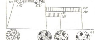
Temperature limits of complete annealing, incomplete annealing, high tempering and normalization, plotted on the section of the iron-cementite phase diagram
Annealing reduces the hardness and increases the toughness of steel, improves its machinability, relieves internal stresses, and also eliminates structural heterogeneity and stabilizes physical properties.
Normalization differs from annealing by an increased cooling rate (in still or moving air). Normalization is used to refine metal grains and increase its strength.
Hardening is the heating of steel above the critical point A3 (Fig. 9), followed by rapid cooling in water, oil or other cooling media. Typically, the purpose of hardening is to obtain a martensitic structure, which is then tempered. Incomplete hardening occurs if hypoeutectoid steel has been heated to a temperature above point Ai but below point A3. Ferrite, contained in such steel along with austenite, naturally does not accept hardening. Hypereutectoid steels are hardened at temperatures above A1, but below Acm, since it is inappropriate to dissolve solid inclusions of secondary cementite during heating.
Temperature limits for forging and hot stamping, plotted on the section of the iron-cementite phase diagram.
When tempering, the steel is heated to a temperature below A1, maintained at this temperature and slowly cooled along with the furnace. Low tempering (175-250°) serves to increase the toughness of steel while maintaining high tensile strength and hardness, reducing internal stresses and obtaining more stable structures. High tempering (up to 700°) is used to increase the ductility and machinability of steel and reduce strength and hardness.
Forging, hot stamping and rolling of steel are carried out at relatively high temperatures. The steel is heated to a temperature 100-150° below the solidus line.
The end of the steel pressure treatment should occur at temperatures close to A3 for hypoeutectoid steel; the process at too low temperatures leads to the structure of the steel becoming rougher and its ductility decreases; the process at too high temperatures leads to an increase in the grain of the steel (overheating) and an increase in its fragility. Overheating can be corrected by heat treatment (annealing, normalization).
When steel is heated to a temperature close to the solidus line AE, oxidation of the metal occurs along the grain boundaries, as a result of which the connection between the latter is disrupted and the mechanical strength drops catastrophically. This phenomenon is called burnout, and it cannot be corrected by any subsequent heat treatment.
The influence of chemical elements on the properties of iron-carbon alloys
An iron-carbon alloy, in addition to iron and carbon (permanent components), contains useful, harmful and permanent (technological) impurities, which have various effects on the properties of structural materials.
Carbon in an iron-carbon alloy can be in the form of iron carbide Fe3C (cementite) or in the form of graphite.
Carbon is the main alloyed component, which is specially introduced to increase strength, hardness and improve the technological and operational properties of structural materials. The influence of carbon on the properties of structural materials depends on the state or interaction of it with iron, i.e., on the formation of a particular structure of the iron-carbon alloy.
If cementite is formed during the interaction of carbon with iron, then the alloy will have high hardness, brittleness and will practically not be machinable by cutting.
If carbon, interacting with iron, forms structures of mechanical mixtures (pearlite or ferrite), then the alloy will have high mechanical and technological properties.
Silicon and manganese in iron-carbon alloys are useful impurities. Silicon enters the alloy partially from the ore, and the bulk comes during the smelting process during deoxidation of the alloy.
Deoxidation is the process of removing harmful iron oxide (FeO) inclusions by introducing deoxidizers (manganese, silicon and various ferroalloys). Deoxidizers combine with iron oxide to form slags that must be removed. A small part of the deoxidizers remains in the iron-carbon alloy. As a rule, most steels and cast irons are subject to deoxidation.
Silicon completely dissolves in the main structure of the alloy to form a solid solution, increases the yield strength, and reduces brittleness. High silicon content (1 ... 2%) gives steel elasticity. In addition, silicon promotes the conversion of carbon from the cementite structure into free carbon in the form of graphite, thereby reducing the hardness and brittleness of the alloys. Manganese enters the alloy during the processing of manganese ores, as well as during the deoxidation process.
Manganese forms a solid solution with iron and also promotes the formation of a chemical compound, so it increases hardness, wear resistance, and strength. High manganese content promotes the formation of cementite, which leads to increased hardness and brittleness of the alloy. In addition, manganese neutralizes the harmful effects of sulfur.
Sulfur and phosphorus in iron-carbon alloys are harmful impurities.
Phosphorus enters the alloy from the ore. The original cast iron, as a rule, has a high mass fraction of phosphorus. Phosphorus has limited dissolution in iron, and its excess content leads to the formation of iron phosphide, a very fragile compound. Phosphorus, dissolving in iron, sharply reduces its density and leads to brittleness in a cold state. This property is called the cold brittleness of alloys. Phosphorus also leads to increased hardness and decreased strength. Manganese, interacting with phosphorus in the process of deoxidation, removes it with the formation of slags.
In some cases, phosphorus can be useful, as it improves machinability, fluidity, and, in the presence of a small amount of copper, increases corrosion resistance.
Sulfur enters the alloy from ores, as well as from fuel during its combustion. Without dissolving in iron, sulfur forms a fusible and very brittle mechanical mixture (eutectic) with it and makes the alloy brittle at red-hot temperatures (this property is called red-brittleness), therefore iron-carbon alloys with a high sulfur content are not subjected to hot pressure treatment.
At a high carbon content in an alloy, the presence of sulfur increases its hardness and brittleness, worsens casting properties, reduces fluidity, increases metal shrinkage when cooling castings and the tendency to form microcracks. The harmful effects of sulfur are neutralized by manganese. When a small mass fraction of manganese is introduced into the alloy, a compound with sulfur is formed - manganese sulfide (MnS) instead of low-melting iron sulfide (FeS). Manganese sulfide is partially removed along with the slag.
Iron-carbon alloys can contain various gases in very low mass fractions: nitrogen, hydrogen and oxygen. These chemical elements are hidden impurities. Due to the complexity of their chemical analysis, the mass fraction of these elements is not determined and is not standardized in technical specifications.
In addition, various metals (tin, zinc, antimony, lead, nickel, copper, chromium, etc.) - random impurities - are found in small quantities. These groups of metals come from both ores and scrap steel processed during the metallurgical process.
All of the listed random impurities are an inevitable consequence of the technological process, i.e. they are not added on purpose. In this regard, the resulting steels with an insignificant mass fraction of nickel, copper, chromium and other metals are not considered as alloy steels.
In addition to natural, permanent, hidden and random chemical elements, special chemical elements are introduced into an iron-carbon alloy (especially steel) in order to change the microstructure of the alloy, physical-chemical and other properties.
Chemical elements specially introduced into an iron-carbon alloy are called alloying elements, and alloys obtained on their basis are called alloy alloys (steels and cast irons).
Aluminum, vanadium, tungsten, molybdenum, copper, cobalt, silicon, nickel, tantalum, titanium, chromium, etc. are introduced as alloying elements.
State standards strictly regulate the mass fraction of useful and harmful impurities in iron-carbon alloys.
In steels, as a rule, the content of these elements, %, is limited to the following upper limits:
Manganese………………………………………………………………………………… 0.8
Silicon ………………………………………………………………………………….. 0.5
Phosphorus………………………………………………………………………………… 0.05
Sulfur…………………………………………………………………………………… 0.05
In cast iron, according to state standards, a higher mass fraction, %, of useful and harmful impurities is allowed (depending on the groups and brands):
Manganese ………………………………………………………………………………… 0.3 … 1.5
Silicon ………………………………………………………………………………… 0.3 … 5.0
Phosphorus………………………………………………………………………. 0.20… 0.65
Sulfur………………………………………………………………………………. 0.08…0.12
Classification of iron-carbon alloys
Various combinations of these elements lead to a large number of alloys, which can be divided into three large groups:
- Technical hardware.
- Become.
- Cast iron.
Technical hardware
Technical iron includes materials containing less than 0.02% carbon. Steels include materials in which carbon is in the range from 0.02 to 2.14%. And the cast iron group includes materials in which the amount of carbon exceeds 2.14%.
Phases of the iron-carbon diagram
In the iron-carbon system there are the following phases: liquid phase, ferrite, austenite, cementite, graphite.
Liquid phase. In the liquid state, iron dissolves carbon well in any proportions [source not specified 1441 days] to form a homogeneous liquid phase.
Ferrite is a solid solution of carbon interpolation in α-iron with a body-centered cubic lattice.
Ferrite has a variable, temperature-dependent limiting solubility of carbon: a minimum of 0.006% at room temperature (point Q), a maximum of 0.02% at a temperature of 700 °C (point P). Carbon atoms are located in the center of the face or (which is crystal geometrically equivalent) in the middle of the edges of the cube, as well as in lattice defects.
Above 1392°C there is high temperature ferrite with a carbon solubility limit of about 0.1% at about 1500°C (point H).
The properties of ferrite are close to those of pure iron. It is soft (Brinell hardness - 130 HB) and ductile, ferromagnetic (in the absence of carbon) up to the Curie point - 770 ° C.
Austenite (γ) is a solid solution of interstitial carbon in γ-iron with a face-centered cubic lattice.
Carbon atoms occupy a place in the center of a face-centered cubic cell. The limiting solubility of carbon in austenite is 2.14% at a temperature of 1147 °C (point E). Austenite has a hardness of 200-250 HB, is plastic, and paramagnetic. When other elements are dissolved in austenite or ferrite, the properties and temperature limits of their existence change [3].
Cementite (Fe3C) is a chemical compound of iron and carbon (iron carbide), with a complex rhombic lattice, containing 6.67% carbon. It is hard (over 1000 HB) and very brittle. Cementite is a metastable phase and, upon prolonged heating, spontaneously decomposes with the release of graphite.
In iron-carbon alloys, cementite as a phase can precipitate under various conditions:
- primary cementite (is released from the liquid),
- secondary cementite (separated from austenite),
- tertiary cementite (from ferrite),
- eutectic cementite and
- eutectoid cementite.
Primary cementite is released from the liquid phase in the form of large lamellar crystals. Secondary cementite is separated from austenite and is located in the form of a network around austenite grains (after the eutectoid transformation they will become pearlite grains). Tertiary cementite is released from ferrite and in the form of small inclusions is located at the boundaries of ferrite grains [4].
Eutectic cementite is observed only in white cast iron. Eutectoid cementite has a lamellar shape and is a component of pearlite. Cementite can be released in the form of small spheres during special spheroidizing annealing or hardening with high tempering. The mechanical properties of alloys are influenced by the shape, size, number and location of cementite inclusions, which allows in practice for each specific application of the alloy to achieve the optimal combination of hardness, strength, resistance to brittle fracture, etc. [5]
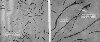
Graphite is a phase consisting only of carbon with a layered hexagonal lattice. The density of graphite (2.3 g/cm3) is much lower than the density of all other phases (about 7.5-7.8 g/cm3) and this complicates and slows down its formation, which leads to the release of cementite during faster cooling. The formation of graphite reduces shrinkage during crystallization, graphite acts as a lubricant during friction, reducing wear, and helps dissipate vibration energy.
Graphite comes in the form of large crab-shaped (curved plate-like) inclusions (regular gray cast iron) or spheres (ductile cast iron).
Graphite is necessarily present in gray cast iron and its variety - high-strength cast iron. Graphite is also present in some grades of steel - in the so-called graphitized steels.
Heat treatment of steels at KVADRO LLC
Our company has been producing custom heat treatment of metals in St. Petersburg for almost a quarter of a century. You can order heat treatment from us by leaving your request by email or calling us.
We carry out heat treatment of steels (including stainless steel, tool steel, etc.) according to the Customer’s drawings or specified conditions, as well as other metals and alloys (aluminum and titanium, brass and bronze, etc.).
The main types of heat treatment of metals carried out at our enterprise to order:
- hardening (including in salt baths, for example, for hardening high-speed cutters);
- vacation;
- annealing;
- normalization;
- improvement;
- cementation.
We also remind you that with us you can use a wide range of metalworking methods, including milling and turning.
Reading an Iron-Carbon Diagram
We can see the composition of an alloy with a given initial carbon content at a given temperature by moving along a vertical line corresponding to the carbon content in the alloy.
Consider, for example, the AEC region. It is adjacent to areas of austenite AESG and the liquid phase. The alloys in it consist of a liquid phase and the resulting solid austenite. How to determine the carbon concentration in different phases for a given alloy? Let us consider, as an example, an alloy with an initial carbon concentration of 2.5% at a temperature of 1250°C.
Let’s draw a horizontal straight line from this point on the graph “2.5% C – 1250°C”. The intersection of this straight line with the AE line bordering the austenite region will show the carbon concentration in austenite at a given temperature (~1.5%).
The intersection of the same horizontal line with line AC, bordering the liquid phase region, will show the concentration of carbon in the liquid phase at a given temperature (~3.5%).
This is how we can determine the carbon concentration in the phases of any alloy at a given temperature:
- in the liquid phase and austenite in the AEC region;
- in the liquid phase in the CDF region (carbon concentration in cementite, of course, is constant - 6.67%);
- in austenite in the SEFK region;
- in ferrite in the QPKL region;
- in ferrite and austenite in the GPS region.
As we can see, at a carbon concentration above 2.14%, the saturation of the cooled melt with carbon always tends to 4.3% (along the AC and DC lines) as it approaches a temperature of 1147°C (ECF level). Next, the liquid transforms into ledeburite (eutectic). Naturally, with the same average carbon content.
As the temperature approaches 727°C (PSK level), the carbon concentration in austenite (“free” and/or included in ledeburite) tends to 0.8% (according to the GS and ES lines). Next, the transformation of austenite into pearlite (eutectoid) occurs. Perlite, of course, has an average carbon content of 0.8%.
Properties of commercially pure iron
Magnetic properties of iron at different temperatures:
- less than 768° C – ferromagnetic;
- more than 768° C – paramagnetic.
And the temperature point of 768° C is called the magnetic transformation point, or the Curie point.
Properties of technically pure iron:
- hardness – 80 HB;
- temporary resistance - 250 MPa;
- yield strength – 120 MPa;
- relative elongation 50%;
- relative narrowing – 80%;
- high modulus of elasticity.
Components in the iron-carbon system
Austenite
The atoms are placed in a face-centered cell. The hardness of austenite has a hardness of 200 ... 250 Brinell units. In addition, it has good ductility and is paramagnetic.
Iron
Iron is a material classified as a metal. Its natural color is silver-gray. In its pure form it is very plastic. Its specific gravity is 7.86 g/cc. cm. Melting point is 1539 °C. In practice, industrial iron is most often used, which contains the following impurities - manganese, silicon and many others. The mass fraction of impurities does not exceed 0.1%.
Iron
Iron has such a property as polyformism. That is, with the same chemical composition, this substance can have a different crystal lattice structure and, accordingly, different properties. Modifications of iron are called respectively - B, D, D. All these modifications exist under different conditions. For example, type B can only exist at a temperature of 911 °C. Type G can exist in the range from 911 to 1392 °C. Type D exists in the range from 1392 to 1539 °C.
Each type has its own crystal lattice shape, for example, type B has a cube-shaped lattice, type G lattice has a face-centered cubic shape. The D-type lattice has the shape of a volume-centered cube.
Another property is that at temperatures below 768, iron is ferrimagnetic, and as it increases, this property is lost.
The points of polymorphic and magnetic transformation are called critical. On the table they are designated as follows - A2, A3, A4. Digital indices indicate the type of transformation. To more fully distinguish the transformation of iron from one type to another, the indices c and r are added to the designation. The first one talks about heating, the second one talks about cooling.
Iron polymorphs
With high ductility parameters, iron does not have high hardness; on the Brinell scale it is equal to 80 units.
Iron has the ability to form solid solutions. They can be divided into two groups - substitution and implementation solutions. The former consist of iron and other metals, the latter of iron and carbon, hydrogen and nitrogen.
Carbon
Another component of the system is carbon. It is a non-metal and has three modifications in the form of diamond, graphite and coal. It melts at 3500 °C.
Allotropic modifications of carbon
In an iron alloy, this element is found in the form of a solid solution, it is called cementite or in the form of graphite. In this form it is present in gray cast iron. Graphite is neither ductile nor durable.
Cementite
Cementite (Fe3C) is a chemical compound of iron and carbon (iron carbide), contains 6.67% carbon. More precise studies have shown that cementite can have a variable carbon concentration. However, in the future, when analyzing the phase diagram, we will make the assumption that Fe3C has a constant composition. The crystal lattice of cementite is rhombic, specific gravity 7.82 g/cm3 (very close to the specific gravity of iron). At high temperatures, cementite dissociates, so its melting point is unclear and is approximately 1260° C. It does not experience allotropic transformations. The crystal lattice of cementite consists of a series of octahedra, the axes of which are inclined to each other. At low temperatures, cementite is weakly ferromagnetic, losing its magnetic properties at a temperature of about 210° C. Cementite has high hardness (more than 800 HB, easily scratches glass), but extremely low, almost zero, ductility.
Cementite is capable of forming substitutional solid solutions. Carbon atoms can be replaced by non-metal atoms: for example, nitrogen; iron atoms - metals: manganese, chromium, tungsten, etc. Such a solid solution based on a cementite lattice is called alloyed cementite.
If graphite is a stable phase, then cementite is a metastable phase. Cementite is an unstable compound and, under certain conditions, decomposes to form free carbon in the form of graphite. This process is of great practical importance in the formation of the structure of cast iron.
Primary cementite
Metallurgists distinguish three types of this substance - primary, secondary, tertiary.
Cementite: forms of existence
This is the name given to the compound of carbon and iron. It is a component of cast iron and some steels. It contains 6.67% carbon.
Its crystal includes several octahedra; they are located with respect to each other at a certain angle. Inside each of them is a carbon atom. As a result of this construction, the following picture is obtained - one atom comes into contact with several atoms of iron, and iron, in turn, is connected with three atoms of this element.
Crystal lattice of cementite
This substance has all the properties that are inherent in metals - electrical conductivity, a peculiar shine, high thermal conductivity. That is, a mixture of iron and carbon behaves like a metal. This material has a certain fragility. Most of its properties are determined by the complex structure of the crystal lattice.
This material melts at 1600 degrees Celsius. But there are several opinions on this matter; some researchers believe that its melting point lies in the range from 1200 to 1450, others determine that the upper level is 1300 °C.
Primary cementite
Metallurgists distinguish three types of this substance - primary, secondary, tertiary.
Iron-cementite diagram
Primary, obtained from the liquid during hardening of alloys that contain 5.5% carbon. The primary one has the shape of large plates.
Secondary
This element is obtained from austenite when the latter is cooled. On the diagram, this process can be seen in the Fe – C diagram. Cementite is presented in the form of a grid placed along the grain boundaries.
Tertiary
This type is derived from ferrite. It is shaped like needles.
There are other forms of cementite in metallurgy, for example, Stead's cementite, etc.
Other structural components in the iron-carbon system
Perlite
Perlite is a mechanical mixture that consists of ferrite and cementite. Ledeburite is a variable solution.
Perlite
At temperatures from 1130 to 723 ° C, its composition includes austenite and cementite. At lower temperatures it consists of austenite replacing ferrite.
Other structural components in the iron-carbon system
In addition to components and phases, the system of iron-carbon alloys contains other structural components - pearlite and ledeburite.
Perlite
Pearlite is a eutectoid, a mechanical mixture of ferrite and cementite, obtained as a result of the decomposition of austenite when alloys are cooled below 727 ° C. With slow cooling, pearlite is present in all alloys with a carbon concentration from 0.02 to 6.67%. Under a microscope, perlite can appear either as plates or as grains - granular perlite. Its appearance, as well as its mechanical properties, depends on the cooling rate of the alloy and the type of heat treatment.
Ledeburite in steels
Ledeburite is a eutectic, a mechanical mixture of austenite and cementite, released from a liquid when alloys are cooled below 1147° C. The fundamental difference between the eutectic component and the eutectoid component is that the first is released from the liquid, and the second from the solid solution, in the case of iron-carbon alloys - from austenite . This structural component received its name in honor of the German metallurgist Ledebur.
Cast iron
Alloys on the iron-carbon diagram that contain more than 2.14% carbon are called cast irons. They are highly fragile. The cross section of such cast iron has a light tone, and therefore it is called white cast iron.
On the diagram this is point C, called the eutectic, with a corresponding carbon content of 4.3%. Crystallization produces a mixture of austenite and cementite, collectively called ledeburite. The phase composition is constant.
When the carbon concentration is less than 4.3% (hypoeutectic cast iron), austenite is released from the solution during crystallization. Next, C2 is isolated from it. And at 727° C, austenite turns into pearlite. The structural state of such cast iron is as follows: large areas of dark-colored pearlite.
In hypereutectic white cast iron (carbon more than 4.3%), upon cooling, structuring occurs with the formation of C1 crystals. Further transformations are carried out in the solid state. The structure is ledeburite, which is the background for fields of dark-toned pearlite. And large layers are Ts1.
Nodal critical points
An iron-carbon diagram with explanations makes it easier to study the kinematics of the formation of various microstructures. Phase diagrams help metallurgists understand which phases are thermodynamically stable, metastable, or unstable. Using them, you can select the appropriate elements for alloying steel. Phase diagrams also show us how to solve problems such as intergranular corrosion, hot corrosion, hydrogen damage, etc.
The characteristic point on the diagram is the eutectic point - the place where several phases meet. In the iron-carbon diagram, the eutectic point is where lines A1, A3 and ACM intersect. The formation of these points is random.
At these points, eutectic reactions occur, in which the liquid phase solidifies and turns into a mixture of two solid phases. This occurs when a liquid alloy of eutectic composition is cooled to its eutectic temperature.
The alloys formed at this stage are known as eutectic alloys. To the left of this point the alloys are called hypereutectic, and to the right - hypereutectic.
conclusions
It is impossible to achieve absolute equilibrium, both physical and chemical, except under special laboratory conditions.
In practice, equilibrium can be close to absolute, but under certain conditions: a slow increase or decrease in the temperature of the alloy is sufficient, which will be maintained for a long time.
Sources
- https://FB.ru/article/340918/diagramma-jeleza-ugleroda-diagramma-sostoyaniya-sistemyi-jelezo-uglerod
- https://PokVorota3.ru/prokat/zhelezo-uglerod-2.html
- https://intehstroy-spb.ru/spravochnik/diagramma-sostoyaniya-zhelezo-uglerod-2.html
- https://NiceSpb.ru/materialy/diagramma-zhelezo.html
- https://pressadv.ru/stali/zhelezo-uglerod.html
- https://wiki2.org/ru/%D0%94%D0%B8%D0%B0%D0%B3%D1%80%D0%B0%D0%BC%D0%BC%D0%B0_%D1%81 %D0%BE%D1%81%D1%82%D0%BE%D1%8F%D0%BD%D0%B8%D1%8F_%D1%81%D0%BF%D0%BB%D0%B0%D0 %B2%D0%BE%D0%B2_%D0%B6%D0%B5%D0%BB%D0%B5%D0%B7%D0%BE-%D1%83%D0%B3%D0%BB%D0% B5%D1%80%D0%BE%D0%B4
- https://generator98.ru/raboty-so-stalyu/tablica-zhelezo-uglerod.html