Most often, a circular saw is used to separate materials. It can be used to cut plastic, concrete, wood, and metal. You can select discs for different materials, but over time the equipment becomes dull and the cutting process slows down. To restore the sharpness of the cutting teeth, you can make a machine for sharpening circular saws with your own hands and resharpen them.
Disc sharpening
How to properly adjust knives on a woodworking machine
To solve this problem you just need to set up the receiving table.
Whenever a planer, thicknesser, or drum sander is used to level flat wood surfaces, you run the risk of “stepping”—an annoying, shallow indentation at the beginning or end of a pass on the workpiece. On thicknesser and drum sanders, the "step" occurs because just as the front feed rollers grip the workpiece, allowing it to rise slightly, the cutterhead or sanding drum removes too much material from its surface, leaving an unsightly depression.
On a planer, the "step" that usually occurs at the end of a pass is caused by the machine's take-up (rear) table being too low. When the rear end of the workpiece leaves the infeed (front) table, it is lowered onto the back table and a rotating planer shaft, the knives of which select a “step” across the entire width of the board.
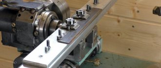
To ensure that “steps” no longer appear on your workpieces, set up your planer for optimal quality work. First, set the cutting edges of the planer shaft blades flush with the surfaces of the front and rear tables. Use a factory or homemade device to adjust the position of the knives. It is important to align the knife blades exactly with the height of the take-up (back) table, and not parallel to the planer shaft, as it may not be parallel to the tables. After aligning the knives, do not turn on the machine, but start setting up the back table. First, for ease of operation, remove the protective devices. Lower the back table 3 mm below the cutting edge of the knife, located at the highest point of the rotation circle. Place a piece of flat plank on the back table so that it touches the cutting shaft.
(We used 19mm thick MDF. Do not use a steel ruler as this may damage the cutting edge of the knife.) Raise the table slightly. Then turn the planer shaft clockwise while pulling the drive belt. If the board moves, raise the table a little more. Repeat these steps until the knives no longer move the board, but only lightly touch it. Finally, secure the receiving table.
The first task that a craftsman faces if he wants to do a quality job is to create an even square workpiece. This article will discuss such nuances as installing jointer knives, their adjustment, and the principles of operation of the tool. In order to form a general picture, you need to consider techniques that allow you to keep your jointer in working condition, after which you can learn some features that should be taken into account when working. Many novice professionals have difficulty setting up knives; first of all, this article was created for them.
The work involved in removing or installing knives largely depends on the fastening mechanism and may vary. In most cases, even a novice will have no difficulty removing the jointer blade and putting it back.
It is not the installation of the knives that is of great importance, but the adjustment of the jointer knives and the adjustment of the tables.
It often happens that workpieces have irregularities, for example, convex or concave. Before you rush to adjust the knives, you need to make sure that the problem is not related to the table. This is signaled primarily by concavities. This means that some part of the tables is tilted below the desired height. To determine the unevenness of the table, use a straight ruler. Convex edges indicate that the inside of the tables is excessively inclined towards the cutting head.
How to make a tenon and groove using a hand router with a dovetail cutter
In this article, we will introduce you to the process of cutting various joints with a hand router, and consider the process of making additional devices for increasing labor productivity, such as tenoning templates and a dovetail wood cutter.
How to make a tongue and groove with a hand router
To make this tenon joint, we will need the router itself and the work table. To facilitate the process, you can make an additional device such as a conductor.
The procedure is as follows:
- We install two slatted stops on a plywood sheet, cut out holes to suit the size of the groove for the drawer and the leg. Rack stops must be secured across the width of the router. They fix it across the working plane. To fix the longitudinal displacement, two other stops are placed at the ends of the intended location for installing the joinery machine.
- To move the workpiece along its length, we mount a pair of bars to the tabletop that correspond to the dimensions of the workpiece.
- We mark the axis and dimensions of the grooves. We install the additional device so that the markings on the workpiece and the jig completely coincide.
- It is necessary to set and secure the stop.
- Secure the jig to the bars using self-tapping screws.
- It is necessary to take a straight cutter and set the milling depth, taking into account the thickness of the manufactured jig. After this, you need to fix the workpiece with a clamp and process the groove.
Let's start cutting out the spines.
- For small production volumes, it is best to do this on a circular machine.
- First you need to measure the depth of the groove, which will correspond to the length of the tenon.
- We measure the resulting value on our workpiece. The length of the tenon will be determined by the difference between the width of the workpiece and the length of the groove, the height of the workpiece and the width of the groove, divided in half. The resulting material residues should be removed to obtain a spike.
- After this, you should set the size on the machine equal to the length of the groove, taking into account its width. The circular saw should be fixed at a level equal to ½ the difference between the width of the workpiece and the length of the groove from the tabletop line. Make a couple of cuts along the length of the tenon.
- We fix the saw blade at a height equal to ½ of the difference in the heights of the workpiece and the width of the groove from the tabletop line. Two cuts are made from the end of the workpiece.
- Let's start sawing. To do this, it is necessary to fix the circular saw to the length of the tenon, and the distance from the disk to the stop should correspond to a value equal to ½ of the difference in the width of the workpiece and the length of the groove. We make two cuts along the width of the product on both sides.
- We adjust the distance from the cutting disc to the stop. It should be equal to a value equal to ½ of the difference between the heights of the workpiece and the width of the groove. We make two slits. We round off the edges of the resulting tenon with a carpenter's knife and sand it with sandpaper.
Tenon cutter for router
Tenoning templates come in a variety of configurations. They serve to facilitate the work of cutting joints such as tongue and groove, as well as to speed up the work. With their help, you can make frames, box joints, and cut out various joints for furniture.
The size of the groove, as well as the evenness of its edges, will depend on the shape of the template tooth. To make a tenon cutter with your own hands, you will need guides, with the help of which you will mill the tenons. They should be mounted on two opposite sides of the housing in a checkerboard pattern, located equidistantly.
If these conditions are met, they will fit together perfectly.
Dovetail wood cutter
They are most often used in conjunction with milling machines and machines for making grooves in products made of hard and soft wood. Manufactured from monolithic hard alloys.
Designed to work in conjunction with cylindrical cutters.
How to choose a groove with a router
When performing this work, you need to know that the technique will directly depend on the location and size of the groove. If it is open, then your tool is attached to the tabletop, and the workpiece is guided along the cutter. Accuracy will depend on the position of the plank and the height of the cutter.
To avoid mistakes during the sampling process, always make a test run on scrap wood. Sampling should be done in stages, several passes must be made. After each pass of the cutting part of the router, to prevent it from overheating, it is necessary to remove waste from the working surface of the tabletop.
This can be done using a template cut out of plywood, which should be followed by a cutter with an upper bearing.
We hope that the information obtained from reading this article will be useful to you and useful for use in the household.
Estimating and setting the required inclination angle
By analyzing the characteristics of the marks left by the sharpening stone, it is possible to correctly assess the angle of inclination by selecting the desired proportions. Then a holder with a knife is installed on the fixed stop. Adjustment is carried out using the stop screws; you need to lower the holder until it touches the stone. Using the angle adjustment screws, select the required parameter in relation to the stone. When rotating manually, the marks on the painted blade determine the need to adjust the angle of the holder. And if necessary, such adjustments are very easy to make.
Operating angle range 30-45 degrees. Its exact degree is determined by the specific type of tree. Its quality will depend not only on the angle, but also on the reach of the knife and the diameter of the head. The classic parameter is considered to be 40 degrees. When choosing a specific number, do not forget that the cutters are designed according to a standard backing. If you increase the angle, there is a risk of the butt rubbing against the workpiece. And if you reduce it, the cutting edge will become weaker and thinner.
Differences in insert teeth
The tooth of hard alloys has four main planes for work: front, back and lateral (auxiliary). When the planes intersect with each other, cutting edges are formed: the main one and a pair of auxiliary ones.
The shape of the teeth is as follows:
- Direct. The use of this form will be justified when longitudinal cutting is required, which is quick in time and not required in quality.
– Oblique or beveled. The angle of inclination of the rear shape can be right or left, they alternate with each other. This configuration is the most common. Sharpening blades of different sizes are used to work with different materials in any direction.
– Trapezoidal. This tooth dulls its edges more slowly than a beveled tooth. Alternate it with the straight one. In this case, the rough cut was a longer trapezoidal cut, and the finishing cut was a short straight cut.
– Conical. This form of teeth performs a rough cut on the lower edge of the boards, while protecting the upper edge from chipping. Basically, the front edge of such an element is flat. But if you make it concave, then it is possible to use this device for cross cutting in a finishing version.
Read also: Blueing stainless steel at home
Installation of knives on the shaft.
The slots or areas for the knives on the shaft should be smooth, without roughness. The edge of the shaft on which the cutting edge of the knife rests, the so-called chip breaker, must be smooth and sharp; nicks and crumbling of the edge are not allowed.
The knife shaft should lie in the bearings without play and be easily turned by hand.
The knives are installed in the nest so that the knife blade protrudes (overhangs) above the edge of the chip breaker by an amount of 0.25 to 2.km (usual limits are from 1 to 1.5 mm). Large euro is used in cases where it is desirable to increase the cutting angle.
The position of the blades of all knives in relation to the machine table should be exactly the same. This is achieved by aligning the knives on the machine. To do this, the knives are first screwed in lightly, so that they can be easily moved by blows of a wooden hammer or by tightening the adjusting bolts.
To check the position of the knives, the following methods are used:
A. Checking with a wooden template.
A template is made from hard wood (Fig. 242). The machine table is installed so that the template can be inserted under the knife shaft (when installing a thickness planer). Holding the template firmly on the table with one hand, turn the knife shaft by the pulley or clutch with the other (with a belt drive, the belt must be removed; in an electrified machine, the motor must be de-energized during installation) and bring the knife blade to the template. The table is then positioned so that the knife blade lightly touches the template. Having installed the table at one point, check whether the template touches evenly along the entire length of the knife blade.
Rice. 242. Scheme for installing knives using a template.
The rest of the knives are checked in a similar way. After checking, the knives are tightened with a normal doot-kaza wrench, starting from the middle to the edges.
Lengthening the arm of the wrench to increase tightening is not allowed.
b. Checking the installation using the Vadkin template.
The wooden template described above is convenient for checking the installation of knives on the surface planer. To check the installation of knives on the jointer, the Vadkin template is more convenient. The template consists of a ruler, at the ends of which two control templates protruding forward are installed (Fig. 243). The templates are pulled out at an equal distance from the edge of the table and first one knife is installed on them, and then the rest.
Rice. 243. Installation diagram of knives according to the Vadkin template.
When installing knives in square shafts, washers must be placed under the nut or bolt head.
c.Check with indicator.
The considered methods can only ensure relative accuracy of knife installation. To obtain high purity of processing, an installation accuracy of within 0.0025 is theoretically required, but checking using templates gives an accuracy of up to 0.05. A more advanced and at the same time quite quick way is to check the installation with an indicator. An accurate and sensitive indicator is installed on a special stand with a polished base (Fig. 244). By placing the indicator on the knife blade at one point and moving it along the knife on the table, you can set the knives with the almost necessary extreme accuracy.
The described methods allow you to perform a static check of the installation of knives (static alignment) on the machine. After checking, the knives are finally fixed on the knife shaft.
Using a special device (Fig. 245), you can install and check the cutter head outside the machine. At the same time, installation and alignment operations take significantly less time.
The required installation accuracy depending on the feed amount, ensuring processing with both knives, can be selected using the graphs in Fig. 246 and 247.
Static alignment allows you to install the knives with sufficient accuracy in relation to the geometric axis of the shaft. However, at high peripheral speeds of the knife shafts (common in modern machines), a deviation of the geometric axis from the actual axis of rotation occurs. Due to the elasticity of the knife shaft and bearings, off-axis of the rotating shaft appears, due to which the trajectories of the knives, even with the most accurate installation, may not coincide. This misalignment increases sharply and can exceed 0.25 mm if the cutter shaft and knives are not balanced and especially if there is play in the bearings, the transmission belts are too tight, or the operation of the self-centering devices with removable heads is disrupted.
To check the dynamic balancing of the knife shaft, use a special device with a “pencil” (touchstone) (Fig. 248) made of hard abrasive with a cross-section of about 25 mm. This device consists of a frame along which a carriage with a “pencil” moves using a worm clutch. The frame is firmly fixed to the machine bed above the knife shaft, and the keystone is installed so that when the shaft is rotated, the knives approach it without touching, but with minimal clearance. After this, the knife shaft is set in motion, and the whetstone is given translational motion along the knife shaft by rotating the handwheel. In case of misalignment, which appears during rapid rotation of the shaft, the knives, deviating, will touch the touchstone and grind off. When moving the carriage to one side or the other, the deviations of the knives can be gradually removed.
Rice. 244. Scheme for installing knives using an indicator.
Rice. 245. A device for installing and aligning the knife shaft outside the machine.
When checking the balancing with such a whetstone, it is necessary to ensure that the whetstone does not come too close to the knife blade, which can cause too sharp an impact on the knife blade. The forward movement of the whetstone along the knife shaft should be uniform and not too fast.
SF-6 Single-sided jointing machine. Purpose, scope
The single-sided jointing machine SF-6 is designed for jointing (linear planing, longitudinal milling) of wood blanks of various species along a plane and at an angle.
The machine is used in enterprises of the furniture and woodworking industries (furniture, house-building, automobile and carriage building, etc.), model shops of machine-building plants, and construction organizations.
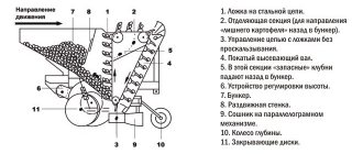
The bed is made of cast iron, solid cast, box-shaped, inside which an electric motor drives the knife shaft.
Rotation of the knife shaft is transmitted by V-belts. To tension the belts, vertical movement of the under-motor plate is provided. The belt drive is covered with a casing.
The knife shaft supports are mounted in a single block with detachable covers, which reduces mechanical noise and vibration from the rotation of the knife shaft. The blade shaft is braked via a belt drive by an electric motor.
Feeding of workpieces on the machine is carried out manually or mechanically using an automatic feeder. The front and rear tables are cast iron, polished plates with stiffening ribs along the lower plane. The front and rear tables of the machine are adjusted vertically by means of eccentric rollers through a system of levers and rods driven by a handle for the front table and a screw with a nut for the rear table.
Shields are installed on the sides of the table. Gouging depth indicator - the dial is placed in the dashboard window. The guide ruler is moved manually. The ruler can be moved across the table depending on the width of the material being planed and can be set to the required angle in the vertical plane (up to 45°).
The machine has a round two-knife shaft with wedge fastening of knives.
Planing width on the machine is 400 mm, the thickness of the removed layer is 6 mm, the diameter of the knife shaft is 125 mm, the cutting diameter is 128 mm, the number of knives on the shaft is 2, the power of the knife shaft electric motor is 2.8 kW, the number of revolutions of the knife shaft per minute is 5000, the weight of the machine is 620 kg.
Setting up a hand plane, sherhebl and jointer
A plane is a tool for working with wood. In the hands of a good craftsman, with his help, a nondescript board can turn into a real work of art. It will become smoothly sanded and perfectly level if necessary. Or, if necessary, you can make a notch in it using a plane. They remove shavings in order to give the wooden surface the desired shape and smoothness. The thickness of the chips may vary depending on what is required to be obtained as a result of the work.
Craftsmen, as a rule, use hand planes. The application technique requires certain skills; anyone can acquire them. Often this tool turns out to be indispensable for work, and it is impossible to use an electric plane instead of a manual one. This applies to cases where surface smoothness is required to be almost perfect. It is more difficult to achieve this result with an electric planer.
In order to use this tool for its intended purpose, you need to configure it. To do this correctly, you will need to follow the steps for setting up your plane. Only in this case will it work as it should. Every craftsman should know that the adjustment of planes, jointers and sherhebels determines the quality of the work. And it needs to be carried out in such a way that it is convenient and reliable to use.
Exploitation
Before you start making this unit yourself, you need to think through the drawings of a machine for sharpening circular saws. You can calculate them yourself, or you can turn to a professional. In any case, in order to understand all the intricacies of the future device, you cannot do without a preliminary paper version. If you have the necessary knowledge, you can cope without turning to a specialist.
A machine for sharpening circular saws, created with your own hands, has a big advantage in terms of price over a factory unit. It also does not require any special skills to operate.
Making a machine yourself
To begin with, determine the number of functions of the future unit. It could be:
- just a planer with one planing operation;
- a combination of a jointer and a circular saw, which doubles the usefulness of the equipment;
- they add grinding, sharpening and drilling functions, but for your own workshop, making a complex set of equipment with your own hands is a difficult task.
Often, craftsmen independently make a jointing machine with a sawing function, while the torque is transmitted from one electric motor, which includes structural elements:
- The bed can support the weight of the work plane and installed electrical and mechanical equipment. In a workshop, a channel with a shelf thickness of at least 10 mm is used to make the frame. The structure can be made stationary (welded) or provided with bolted components for disassembly if necessary. The first option is more reliable and is used if a portable machine is not needed. Sometimes the desktop itself acts as a bed.
- Working tools include knives and saws; the work of processing and sawing workpieces depends on their quality. Reliable and strong steel is used for cutting blades; the saw teeth must be equipped with Pobedit tips.
- Without a rotor, to which all the tools are attached, not a single woodworking machine will function, so attention is paid to its selection. Most often it is made by a specialist turner according to the drawings offered to him.
- The design of a jointing unit with a sawing function provides three working surfaces - one serves as a table for the circular saw, the other two feed and receive the workpiece during the jointing process. Multilayer plywood, the thickness of which is at least 5 mm, or sheet metal, is used as a covering. Typically, the feed surface is made 2-3 mm below the receiving side to facilitate the process and reduce vibration load.
Electric drive of the machine
The operation of the jointer and saw is based on rotational functions, which is why the drive is called the heart of the unit. A three-phase motor is suitable as an electric motor; sometimes the wiring is re-equipped for this in the workshop. Three-phase units with a voltage of 380 V are characterized by high power and suitable torque. The minimum permissible engine power is 3 kW, the maximum is not limited. The transmission of rotation from the engine to the shaft is carried out by means of a belt drive. V-shaped double-ribbed belts work well in such conditions; they are reliable in operation. The electric motor is mounted using a console inside the frame structure of the bed; the installation method helps to regulate the tension of the belts. Another way is to mount it using a slide - this still allows for adjustment, but the engine itself is more firmly fixed.
Finishing the characteristics of the cutter
This is a more precise operation performed on machines with diamond wheels. This sharpening method is most often used when it is necessary to remove obvious defects. For example, if a wood lathe cutter has burrs, cracks or nicks. In this case, the working process is carried out under mechanical control. That is, the tool being processed is fixed in a vice and controlled by a hydraulic or electric drive. The operator adjusts the cutter displacement parameters in accordance with the requirements for its correction parameters.
Safety precautions when working with a woodworking machine
Technical documentation of any equipment includes instructions for operation and maintenance. When purchasing a woodworking machine, carefully study all accompanying documents. Woodworking machines are considered high-risk equipment. During work, the master is faced with high voltage, moving components and cutting tools. To avoid injury, electric shock, or fire while operating the machine, basic safety precautions should be strictly followed. Before starting work on a woodworking machine, prepare your work area.
- It should be clean and well lit.
- Remove all things that clutter the work surface.
- There should be no flammable liquids or gases in the room where carpentry work is carried out. Sparks flying during operation can cause fire.
- To avoid an accident, children and strangers should not be near the machine.
People who have reached the age of majority and have appropriate training, who are well aware of the structure of the machine and the operating rules, are allowed to work on a woodworking machine. You should be extremely careful when working with a woodworking machine. Avoid being distracted by extraneous thoughts and conversations to avoid injury. You should not work when you are tired or not feeling well. It is strictly forbidden to use the equipment while under the influence of alcohol or drugs. When making products on a woodworking machine, always observe personal safety:
- Work in special clothing. It should not be bulky or loose. No long sleeves, belts, ties or scarves. Tuck long hair into a ponytail or under a hat. Remove rings from your fingers and bracelets from your wrists.
- Hands should be clean, dry, without traces of oily liquids.
- Use personal protective equipment: respirator, mask, goggles, gloves, headphones.
Equip your workshop with fire extinguishing equipment: a fire extinguisher, a box of sand. There should also be a first aid kit with medicines and dressings so that in case of injury, first aid can be quickly provided.
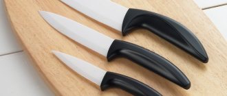
Adjusting tool knives
A woodworking master knows very well how to adjust the knives on an electric planer. To perform this work you must have:
- Hexagon included with the product.
- Metal ruler.
In order to set up a tool with several knives quickly and correctly, it is necessary to follow a certain technological sequence:
- Turning the device over, you need to remove tar deposits from the canvas with a solvent.
- The front side of the sole is exposed. Its position must correspond to the minimum planing depth.
- Each blade is installed in the gap between the plates.
- The ruler is placed on the base plate. Moreover, the cutting edge must touch the supporting surface. If this does not happen, you need to loosen the fastening bolts and set the desired level.
- Then tighten the bolts.
- All attachments are subjected to the operation. The exposed gaps must have the same dimensions. As a result, vibration and tool imbalance are eliminated.
- To determine the ease of rotation of the drum on the shaft, you need to turn it by hand.
- To check the correctness of the settings, process the unnecessary workpiece.
If the knife has a straight shape, the protrusion of the working part should reach 0.5 mm. For a rounded shape, this size should be more than 1 mm.
Types of turning tools
The general segment of turning tools in the main classification involves the division of equipment by purpose - for wood and metal. In this case, the first type is considered. Such models differ from metal cutters in the material of manufacture. Technologists use tool grades of steel, while metal processing is carried out with cutters made of carbon hard alloys.
Also, different types of cutters for a wood lathe differ in design. The working part can be straight, bent, drawn or curved. The choice of one or another type of cutter is determined by the wood processing method, cutting characteristics and equipment. By the way, the parameters for integrating the equipment into the fastening zone also determine differences in the design of the shank. Modern machines focus on versatility, that is, the ability to work with rectangular, round or square holders. Moreover, in this aspect, differences between cutters for metal and wood are most often not made.
Sharpening process and operating rules
The main feature of the jointer knife sharpening technology is the correct choice of angle relative to the abrasive and maintaining a constant value of this parameter during the processing process. It is necessary to ensure that the jointer knives do not touch only the edge of the stone. Experts try to stop the holder at a distance of at least ten millimeters from the edge. To simplify this task, special stops are installed on the sharpener. Their location limits the free movement of the holder.
The operation continues for a long time, which can lead to a change in the temperature on the surface of the blade and cause its deformation. This causes a disruption of the metal structure and a decrease in its physical and mechanical characteristics. To eliminate this problem, a forced cooling system is used. It should be set to spray water evenly across the entire jointer blade. The supply of water or other cooling liquid is carried out from a special container located in close proximity to the grindstone. During work, you should monitor its presence. A waste water drainage system should be provided.
Long-term use of a sharpening stone can lead to an unpleasant effect, the so-called clogging. This causes the abrasive elements to slip and reduces the quality of sharpening of the jointer knife. This drawback can be eliminated by periodically cleaning the stone and giving it the required geometric shape.
In addition to observing the temperature regime, it is necessary to constantly monitor the quality of the sharpening stone. It must remain clean during the entire operating mode. Bringing it back to normal condition involves regular cleaning and giving it the required geometric shape. To solve this problem, bars with different abrasive grains are used. If the cutting tool of the jointer is made of softer grades of steel, turning will go much faster and the whetstone is less susceptible to clogging.
Modern manufacturers make cutting tools for jointers from various grades of steel. Mostly tool steel or softer grades of steel are used.
Sharpening is performed by smoothly moving the holder to the right and left without strong pressure. It is advisable to place the holder with the attached tool at a distance of no closer than twelve millimeters from the edge of the stone.
After high-quality sharpening, the tool has a sharp blade at a given angle. All that remains is to bring the blade to full readiness. For this purpose, leather wheels and polishing pastes are used.
Proper sharpening lasts about twenty minutes. After completion of the main work, finishing is carried out. It is made using polishing paste or mastic. The surface takes on a perfectly smooth shape. Otherwise, the tool will not allow you to obtain the required surface quality of the workpiece. The resulting quality of the cutting edge is checked by checking the ability to evenly cut a sheet of plain paper. The result should be a neat, even cut.
Planer-thicknesser unit
It is a combined machine with a combination of thicknessing and jointing processing. After the initial sawing of the boards, they are sent to the final removal of all irregularities. It differs from a planing unit in that it allows planing to a selected depth. The knife shaft with blades is located between the receiving table, fastened to the frame, and the receiving surface; in some models, the cutting tool is installed under the table or on top of the plane. To set it to size and adjust it, use a ruler attached to the body.
Simultaneous jointing and surface planing allows the workpiece to be planed to a selected depth, which is why it is used in large production facilities. It works great on a construction site, where wood is delivered with primary processing, and subsequent planing to size is carried out on the site before installation in the structure.
Sources
- https://palitra21.ru/oborudovanie/kak-pravilno-otregulirovat-nozhi-na-derevoobrabatyvayushhem-stanke.html
- https://moy-instrument.ru/instrumenty/kak-pravilno-otregulirovat-nozhi-na-derevoobrabatyvayushhem-stanke.html
- https://BurForum.ru/tehprocessy/kak-otregulirovat-nozhi-na-strogalnom-stanke.html
- https://spk-kovka.ru/proizvodstvo/nastrojka-strogalnogo-stanka.html
- https://lanos-volgograd.ru/regulirovka-stolov-na-rubanke/
- https://mehmanxona.ru/osnastka/kak-vystavit-nozhi-na-fuganke.html
[collapse]