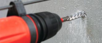
What is a gun drill and what is it used for?
A gun drill is a cutting tool of a predominantly cylindrical shape with a cross-section that varies along its length. It is a single-cut tool.
To remove waste chips from the workpiece, there is a recess on the surface of such a drill with a cross-section in the shape of the letter V. This groove is made along the outer surface of the drill.
In general, using a gun drill it is possible to produce holes with a diameter ranging from 0.5 millimeters to 10 centimeters. There is usually no special hole for supplying coolant. Drilling is carried out at a low speed of rotation of the metalworking unit.
In the working part, the gun drill has the shape of a semicircle. The flat surface of the semicircular rod is the front surface of the drill. At a right angle to the axis of the drill, a cutting edge is formed at the end of the rod. The rear end of the tool has a flat, inclined shape at an angle of 10-20 degrees.
To ensure more precise guidance, the supporting surface of the gun drill is cylindrical. On the supporting surface, flats are made at 35-40 degrees, as well as a reverse cone of 0.04-0.05 millimeters per 10 centimeters of length. These measures help reduce friction between the tool and the internal walls of the workpiece.
To remove chips formed during the cutting process, you have to regularly remove the drill from the part. The geometry of the drill contributes to the harsh operating conditions of the tool, which reduces its durability and reduces the accuracy of the cutting process.
Note that in modern metalworking there are more accurate and productive ways to produce deep holes. Processing a part with a gun drill is considered an outdated and ineffective method of deep drilling.
Electrochemical piercing of small diameter holes
Electrochemically, using the circuits shown in Fig. 16 , small diameter holes are obtained.
Rice. 16. Schemes of electrochemical piercing of small-diameter holes: a - with a tubular electrode; b - jet with an electrode placed in a non-conducting (quartz) tube; c - jet with a quartz tube having a capillary end; g - jet for the hole system; 1 - cathode tool; 2 - workpiece; 3 - insulating coating; 4 - glass tube
During electrochemical piercing with a tubular electrode-tool ( Fig. 16a ), the latter is made in the form of a metal tube (usually made of Nb, Ti or stainless steel) with an insulated side surface. To ensure effective removal of electrochemical reaction products from the interelectrode gap, electrolyte is pumped through the electrode body. Processing is carried out at a current density of 60...140 A/cm2, relatively large values of the interelectrode gap (0.1...0.3) and an electrolyte pressure at the inlet of 0.5...10 MPa. In some cases, to increase the stability of the process, hydraulic resistance to its flow is artificially created at the electrolyte outlet.
The advantages of electrochemical piercing are the absence of mechanical and thermal influences, which makes it possible to obtain good surface quality and practically avoid EI wear, burrs and sharp edges.
The disadvantages include hydrogenation of the surface layer of the hole, low processing speed (0.5...4.0 mm/min) and instability of the process due to unfavorable conditions for the evacuation of electrochemical reaction products. The use of high-quality acid-resistant coatings that have good adhesion to the surface of the tool electrode is required. The latter is the most significant technical limitation in the use of electrochemical piercing to produce holes with a diameter of less than 0.5 mm.
With electrochemical jet piercing ( Fig. 16b, c ), a cathode made of a noble metal (Au, Pt) is placed in a quartz or sapphire tube. This design of the EI eliminates the possibility of a short circuit, and in the presence of an elongated capillary end makes it possible to obtain holes up to 0.1...0.2 mm.
The main disadvantages of electrochemical jet piercing include: low EI feed rate (no more than 4 mm/min); the need to use high operating voltages (400–1200 V) and pumping pressure (up to 10 MPa); use of aggressive acid electrolytes (15...30% aqueous solutions of HСl, H2SO4, HNO3); fragility and clogging of the capillary parts of quartz tubes.
Systems of small diameter holes can be obtained according to the scheme shown in Fig. 16 The treatment is carried out by laminar jets of electrolyte, formed by supplying electrolyte under pressure through a titanium cathode tool.
Technical indicators of the considered methods of flashing holes are given in table. 4 .
Table 4
| Parameter | Firmware with a tubular electrode | Jet with electrode in a quartz tube | Jet with electrode in a quartz tube | Flashing with electrolyte jet |
| Minimum hole diameter, mm | 0,5 | 0,2 | 0,125 | 0,125 |
| Maximum length/diameter ratio | 300 | 100 | 40 | 30 |
| Processing accuracy, ± mm | 0,03 | 0,03 | 0,03 | 0,05 |
| Firmware speed, mm/min | 1…3,5 | 1…3,5 | 1…3,5 | 1…3,5 |
There is a known method for electrochemical perforation of thin-walled parts using a stencil. It is mainly used to make holes in foils, thin-walled pipes, etc. Electrochemical perforation makes it possible to obtain meshes with a thickness of 5...200 microns with a hole pitch of at least 0.2 mm with a minimum hole diameter of 0.05 mm.
Types of drills for deep drilling
In today's metalworking technology, several types of drills are used for deep drilling of parts.
Let's look at their main types:
- Gun drills. The characteristics of this type of drill were discussed above. Recently, an instrument has been produced with a slightly modified form in relation to the traditional one. This allows you to increase the productivity of the process and the quality of the processed parts. It makes sense to use gun drills when machining small-diameter holes. The length of the holes is usually no more than 40 diameters. Accuracy according to IT9, and surface finish is 0.09 - 3.5 microns.
- Gun drill made as one piece. They are also called monolithic drills because they are made entirely of carbide material. There is a special passage inside the drill to supply coolant. Chips and coolant are removed from the part through an external helical groove. They are used for drilling holes up to 100 millimeters. Depth – up to 100xD. The tool received this name because it was previously used to process firearm barrels.
- Gun drill, made using the technology of fixing cutting plates made of hard alloy by soldering. Like other drills of this type, they provide high dimensional accuracy with minimal deviation of the drilling axis.
- A gun drill with additional cutting inserts. Such drills make the cutting process more productive.
- Twist drills with cylindrical shank. Manufactured in accordance with the requirements of GOST 886-77. They have an elongated cutting part, which can be made entirely of high-speed steel or have carbide inserts. The coolant supply can be either from the inside or from the outside. The shank may also have a cylindrical shape.
- Feather drills. They are used for drilling shallow stepped holes.
- Ejector drills. Used for drilling deep holes in metalworking machines with the cutting tool placed in a horizontal plane.
Pereosnastka.ru
Classification of deep drills
Category:
Deep drilling
Classification of deep drills
Of the entire AIDS system - machine, fixture, tool and part - during deep drilling, the tool that works under the most difficult conditions is the drill. The closed volume and numerous functions, the implementation of which must be ensured by the design of the tool and forced modes, force the drill body, its cutting and guiding elements to work under high stress. This can explain the abundance of all kinds of drill designs, which often have original elements. The authors of these drills, each in their own way and not always with sufficient reasoning, are trying to solve problems that have not yet been solved by researchers and designers.
Existing deep hole drills can be divided into two groups: 1) solid drills and 2) annular drills.
Solid and circular drilling have been known for a long time. Although the ring drilling method should be considered more progressive, solid drilling is more common in industry. In our country, circular drilling is used starting with drilling diameters dc >80 mm. However, it should be expected that this method will gradually replace solid drilling even at smaller drilling diameters. This is evidenced by numerous attempts to use annular drills even for drilling diameters smaller than 30 mm. The reason for the insufficient introduction of ring drilling into industrial practice is its lower reliability and greater complexity of implementation.
Deep hole drills can also be divided into two large groups based on the way they are positioned during drilling.
The basing of the tool when deep drilling is very important, since the drill in this case can only be supported by the surface of the hole that it itself forms. Moreover, in relation to the drill, the basing can be constant (definite) or can change periodically. With constant basing, the resistance forces that arise during drilling in the transverse plane of the drill act all the time in one direction with respect to the drill (Fig. 1, a). With an indefinite basing, these forces are either absent altogether or change their direction relative to the tool during operation (Fig. 1, b and c).
This important point will be discussed in more detail later. For now, we only note that with a certain basing, a transverse force R acts on the tool, which constantly presses the tool to the surface of the drilled hole. If the tool does not have a definite location, then the transverse force R, variable in direction, will swing it during the drilling process. In this case, especially with forced operation, the tool does not provide the required drilling quality. However, despite this, it will be shown in the future that these instruments can be successfully used by introducing additional devices that increase the reliability of their operation.
In a small area of the cutting edge, there is significant loss of carbide. When dividing the width of the cut with several cutters, the damaged section of the replaceable cutting edge can be easily restored by replacing the failed cutter. The advantages of the method of dividing the width of the cut also include the ease of obtaining tool designs that have a constant (definite) location.
Rice. 1. Action of forces in a plane perpendicular to the axis of the drill: a - force is constant in magnitude and direction (R = const; = 0); b - the force is not constant both in magnitude and in direction R; c - force R = 0
According to the loading of the cutting edges, drills, like many other cutting tools, can also be divided into two groups. In this case, a distinction is made between the method of dividing the cutting width and the method of dividing the feed.
When drilling using the method of dividing the cutting width, they mean the number of autonomous cutting edges (the number of tool teeth) required to cover the entire cutting width B. This method should be considered a progressive direction in the design of drills, since covering the entire cutting width with one cutting edge, especially when continuous drilling of holes with a diameter above 40 mm is difficult. The cutting edges are usually composed of carbide inserts, the width of which is limited. Despite the fact that the standard provides for thin plates of large width, in production conditions they are not always available.
The use of wide plates turns out to be in most cases not economically feasible, since any slight chipping of the hard alloy or increased wear of the plate.
Below are formulas for determining the feed per tooth and the excess value for tools used in practice.
Due to the difficulty of sharpening, drills with excess cutting edges are very rare. Sometimes toolmakers, wanting to get a tool that works by dividing the feed method and has a certain location, still try to use such drills.
The next sign of drill classification may be the method of chip removal: internal or external. Both of these methods have their positive and negative sides. The most common is internal chip removal, although its implementation is quite difficult - an oil receiver is required. This method ensures high quality drilled holes, since the waste chips do not scratch the surface of the hole and do not become wedged between the tool guides and the workpiece. In addition, these drills have slightly less wear on the guides. Therefore, the process of drilling deep holes of medium diameters with internal chip removal proceeds more reliably.
Drills for holes with diameters dc
Rice. 2. Graphs of feed distribution to the cutting edges of tools per one revolution of workpieces
Rice. 3. Classification of deep drills. The following symbols are used in the figure: 1 - drills operating by dividing the width of the cut; 2 — drills operating using the feed division method; 3 - drills working using a combined method (drills of groups 2 and 3 must have a number of cutting edges > 2)
Drills can also be classified according to various structural elements. The most significant of them are the designs of cutters and guide drills and the designs of elements for attaching drills to stems.
Small drills have brazed cutting edges and carbide guides. Less commonly used are pressed and sintered metal-ceramic drills attached to the stem by soldering. Drills made of high-speed and tool steel for conventional drilling are also manufactured in one piece - in the form of attachments to the stems.
Drills for drilling holes dc>40 mm most often have replaceable cutters and guides. In most cases, carbide inserts are soldered to cutter holders and guide pads. Less commonly used are drills with mechanical fastening of carbide plates of blades and guides.
In our country, when processing deep holes, drills and other tools with external shanks were often used to attach to stems. In this case, multi-pass threads were cut on the shanks. However, the experience of operating these tools served as the basis for proposing an internal flat single-thread thread for attaching the tools to the stems.
Threads are not suitable for attaching large tools to stems, as they tend to jam on the stem. Therefore, in such cases, end connection with screws and end keys or pins is usually used.
The classification scheme for drills for deep drilling is shown in Fig. 3.
Read more:
Medium-diameter drills with precise alignment
Related articles:
pereosnastka.ru
Important Features of Deep Hole Drilling
Deep drilling of holes in metal is a specific metalworking process and requires an appropriate approach. This operation should be performed on deep drilling machines specially designed for this purpose.
An important feature of the process is the precise centering of the tool and the elimination of drill deviation along the axis. It is necessary to avoid tool runout. To obtain a hole with precise dimensions and a high-quality surface, it is important to provide the processing area with a sufficient amount of coolant.
Chip removal grooves must be smooth to ensure timely removal of chips from the processing area.
Drilling blind holes differs in the direction of complexity in that during the work you need to constantly monitor the depth of the hole. For deep holes this causes some difficulty.
Deep Hole Tool Selection
First of all, the deep cutting tool must match the unit on which you are going to perform cutting operations. The shank must match the chuck of the machine tool or machine gun. Moreover, drills for deep drilling must be installed on units specially designed for these operations.
If during processing you need to strictly eliminate axis deviation while maintaining high accuracy, it is better to use a solid carbide gun drill.
If the material being processed breaks into long chips during processing, a tool with chip flutes with a high surface finish should be used. When working with aluminum alloys, use a tool with a single blade and a 180-degree sharpening of the cutting edge.
Otherwise, you should choose a tool depending on the length and diameter of the required hole.
Basic steps for drilling deep holes
Drilling deep holes in metal is usually performed in the following sequence:
- A preparation hole with a slightly smaller diameter with a tolerance of H8 is drilled into the part.
- The main processing tool is started at low speed and slowly moved towards the end of the part.
- Gradually bring the tool to the speed required by the technology and begin supplying the lubricant and cooling liquid.
- Drill the part to the required depth. In this case, the tool is not removed from the hole.
- If the technology uses a tool of considerable length, then the first quarter of the cut is performed at a reduced rotation speed. The rest of the hole is cut at rated speed.
- When the required depth is reached, the supply of lubricant is stopped.
- coolant to the tool.
- Then the drill is quickly removed from the drilling area and the operation of the unit is stopped.
This technology is standard and may differ depending on the tool used and metalworking equipment.
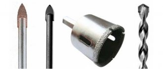
Drilling a hole in hardened steel
The widespread question of how to drill through hardened steel can be associated with the fact that when using conventional technology, the tool quickly becomes dull and becomes unusable. That is why you need to pay attention to the features of drilling hardened alloy. Among the features of the technology, we note the following points:
- It is necessary to properly prepare the hardened workpiece.
- In some cases, a special tool is required.
- Coolant is being used.
If necessary, you can make a drill for hardened steel with your own hands, which requires certain equipment and skills. However, in most cases, a purchased version is used, since it will cope better with the task when cutting hardened steel.
Hardened steel drilling process