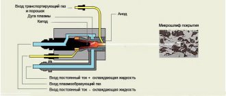
The introduction of modern methods of processing various surfaces significantly improves the quality of products for the domestic and foreign markets. One such technology is ion plasma sputtering. It is a procedure for applying a decorative and protective coating to a metal, plastic, glass and other surface, using vacuum ion-plasma (arc and magnetron) installations as equipment. The main advantages of the ion plasma coating method:
- No change in stoichiometric composition.
- Cleaning the growing coating and base surface.
- High density and strength of the resulting coating.
- Formation of coatings from non-melting or highly refractory material.
- Control over the properties and composition of the coating at the time of application.
Despite the rather high cost of such a process and strict requirements for the cleanliness of the working surface of parts, it is in demand in various fields. The disadvantages of the technology include the rather slow period of processing of products, in contrast to similar vacuum methods. And also a very limited size of the working chambers, which means processing a small number of parts.
Application
High technology equipment can perform ion plasma sputtering using the vacuum method of applying coatings to the surface. This makes it possible to form protective and decorative films from the following metals and compounds:
- silver, aluminum, nickel;
- titanium, niobium, chromium;
- zirconium, tantalum;
- of stainless steel;
- oxides, nitrides of some metals.
For example, ion plasma sputtering of titanium nitride, characterized by an extremely strong film structure and durability of the treated product. Some manufacturers offer a 50-year warranty on this type of coating. Used in the field of restoration and construction work, as well as:
- when decorating offices and facades;
- production of church domes;
- as a roof covering;
- in the manufacture of metal tiles;
- various souvenir products.
Interesting! Thanks to the addition of reactive gases (oxygen, nitrogen, carbon dioxide or acetylene) to the IP spraying process, it is possible to form almost any color shade of the surface.
UVN vacuum spraying installation
The UVN-1M vacuum deposition installation is one of the more practical and useful designs of the provided series. This form of construction contains in a set 4 replaceable scientific and technical modules, each of which represents its own significance in the course of resistive volatilization or sputtering of metals. The device demonstrates itself no less successfully in the spraying of conductive substances, arc evaporation of electrodes from the graphic and in the finishing of carbon nanotextures, which are represented by very complex substances.
Application process
It is the transfer of a sprayed substance in particles from the installation to the required surface of the part/product. It is carried out strictly along a straight path at a pressure level from 1.0-1 to 10-7 Pa. Before starting the procedure, it is necessary to thoroughly clean the working surface from organic matter and inorganic contamination products.
Note! The higher the level of cleaning, the better the adhesion of the coating and, as a result, the better the final result.
Afterwards, it is necessary to carry out mechanical polishing or grinding of the part. Before applying ion plasma coating, the level of surface roughness should be no more than Ra=1.25 µm, and for threads the indicator is different - Ra=2.5 µm. Next, washing is carried out with gasoline and ethyl alcohol to remove abrasives and pastes. The described manipulations should be carried out using an ultrasonic bath.
Then they begin the direct procedure using particles of pure metal or its compounds, for example, ion plasma sputtering of nanocarbon coatings. The final stage is the gradual cooling of the part and keeping it in a vacuum chamber. The finished product can be put into operation and does not require additional processing.
Vacuum spraying “on the knee”
Vacuum spraying (physical vapor deposition, PVD; spraying by condensation from the vapor (gas) phase) is a group of methods for spraying coatings (thin films) in a vacuum, in which the coating is obtained by direct condensation of the vapor of the applied material.
The following stages of vacuum deposition are distinguished:
- Creation of gas (steam) from the particles that make up the spray.
- Transport of steam to the substrate.
- Steam condensation on the substrate and coating formation.
The group of vacuum deposition methods includes the technologies listed below, as well as reactive versions of these processes. Thermal Spray Methods:
- Electron beam evaporation, electron beam physical vapor deposition, EBPVD.
- Evaporation by a laser beam (pulsed laser deposition, pulsed laser ablation).
- Vacuum arc deposition (Arc-PVD): material is evaporated at the cathode spot of an electric arc.
- Molecular beam epitaxy.
- Ion sputtering: The starting material is sputtered by bombardment with an ion stream and delivered to the substrate.
- Magnetron sputtering - we will consider this in the future
. - Sputtering with ion assistance (English ion beam assisted deposition, IBAD);
- Ion beam sputtering.
- Focused ion beam.
Vacuum deposition is used to create functional coatings on the surface of parts, tools and equipment - conductive, insulating, wear-resistant, corrosion-resistant, erosion-resistant, anti-friction, anti-scuff, barrier, etc. The process
is used for applying decorative coatings, for example in the production of gold-plated watches and glasses frames. One of the main microelectronics processes, where it is used for applying conductive layers (metallization). Vacuum deposition is used to produce optical coatings: antireflective, reflective, filtering.
The materials for sputtering are targets made of various materials, metals (titanium, aluminum, tungsten, molybdenum, iron, nickel, copper, graphite, chromium), their alloys, compounds (SiO2, TiO2, Al2O3). A reactive gas, for example, acetylene (for coatings containing carbon), can be added to the process medium; nitrogen, oxygen.
The chemical reaction on the surface of the substrate is activated by heating or by ionization and dissociation of the gas by some form of gas discharge.
Using vacuum deposition methods, coatings with thicknesses ranging from several angstroms to several tens of microns are obtained; usually, after application of the coating, the surface does not require additional processing.
A physical vacuum is a space in which there are no particles of matter and the lowest energy state has been established. However, virtual elementary particles that are born and immediately disappear, affecting ongoing physical processes, have been experimentally discovered in a vacuum. In technology, a vacuum is a state of gas in which its pressure is below atmospheric. Absolute pressure serves as a quantitative characteristic of vacuum. The SI unit of pressure is 1 Pa.
When we talk about vacuum from a technical point of view, we are talking about the use of vacuum in a wide range of pressures - from atmospheric to 10 to minus 10 degrees Pa. A pressure change of 15 orders of magnitude is practically impossible to achieve using only one pump; combined pumping means are required, including pumps of various types and, therefore, various instruments for measuring pressure.
With a large difference in operating principles and designs due to the variety of requirements for pumping equipment, all vacuum pumps use one of two methods for pumping gas:
- movement of gas due to the application of mechanical forces to it in some place in the vacuum system, from where the gas is pushed out;
- binding of gas by sorption, chemical reactions or condensation, usually in a closed vacuum system.
Figure 1 shows the pressure ranges for various types of vacuum pumps:
Rice.
1 Areas of action of vacuum pumps (Source of the picture - No. 2, in the list of sources, under this article)
In positive displacement pumps, pumping is carried out by periodically changing the volume of the working chamber.
The action of mechanical molecular pumps is due to the transfer of gas by moving surfaces of a solid body.
Steam jet pumps perform pumping by imparting additional speed to the molecules of the pumped gas, in the direction of pumping a continuously flowing stream of working fluid steam.
Sorption pumps pump out gases due to their sorption on the surface or in the volume of solids.
The action of ion sorption pumps is based on the removal of gases in the form of ions due to an electric field and sorption of gases on cooled surfaces.
Cryogenic pumps perform pumping by condensation of pumped gases and vapors on surfaces cooled to ultra-low (cryogenic) temperatures. Varieties of cryogenic pumps are condensation and cryosorption pumps.
But let's return to the magnetron sputtering method. Magnetron sputtering is a technology for depositing thin films on a substrate using cathode sputtering of a target in a magnetron discharge plasma - a diode discharge in crossed fields. Technological devices designed to implement this technology are called magnetron sputtering systems, or magnetrons for short (not to be confused with vacuum magnetrons - devices designed to generate microwave oscillations).
In turn, a magnetron discharge is a diode gas discharge in crossed fields (there is a region of space in the discharge volume where the electric and magnetic fields are orthogonal to each other; the magnetic field lines are directed across the current lines):
Rice.
2 Operating principle of magnetron sputtering (Image source: wikipedia.org)
The technological significance of magnetron sputtering lies in the fact that ions bombarding the surface of the cathode (target) sputter it. Magnetron etching technologies are based on this effect, and due to the fact that the sputtered target substance, deposited on the substrate, can form a dense film, magnetron sputtering is most widely used.
Despite the fact that all this may sound quite unusual and even scary for a beginner, nevertheless, the implementation of this process is quite simple and accessible to almost everyone.
To master this process, you can watch a number of videos where it is shown in practice. To power the installation, this or a similar circuit is mainly used, as in the figure below. In it, for simplicity, cost reduction and reduction of current, ordinary 95-watt light bulbs are used:
Rice.
3 A simple version of the power supply circuit for a magnetron device (Image source: IRFC youtube channel)
If it is possible to use LATR, the diagram will look something like this:
Rice.
4 A more universal version of the power supply circuit for a magnetron device (Image source: IRFC youtube channel)
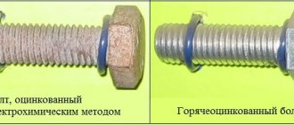
The method allows any enthusiast to touch the world of high technology and get quite amazing results at home, practically “on the knee”, for example, carry out chrome plating
- this process can be carried out in in particular, using the electrochemical method, which consists of using a rather dangerous reagent - chromic anhydride, the danger of which lies in its carcinogenic properties, and the need to drain sufficient quantities of waste water into the sewer system, which is an obvious problem for commercial use, since the disposal of such waste water will cost quite a lot of money, if this process can be organized at all.
Unlike the electrochemical method, magnetron sputtering is very interesting due to the absence of waste water in the process and the need to work with carcinogenic chemicals.
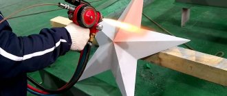
In modern production, even fairly large parts are chrome-plated in this way, among which we can list such as: radiator grilles, car wheels, and other large and small parts: Gold processing
is another quite interesting application. It consists of applying titanium nitride, which makes it possible to give the products wear resistance, as well as a beautiful decorative appearance, “like gold”:
Rice.
5 Application of titanium nitride In general, the use of magnetron sputtering is a very attractive technology in a number of applications, and allows you to truly open up the horizons of high technology and science for any ordinary person, in particular, it is possible to touch the widely advertised graphene and carry out a number of your own experiments with it, and maybe even create your own device using this material!
For magnetron sputtering of graphite and production of graphene
, it is enough to use graphite as a cathode, and hydrogen as a plasma-forming gas, which can be easily obtained using an electrolytic installation, and fed directly after generation directly into a vacuum chamber, after appropriate drying.
When creating micron-thick films of a substance on the working surface, the consumption of the cathode is quite insignificant (it was not possible to find specific indicators, judging by the practical experiences of people).
This, in turn, gives us the opportunity to use quite interesting materials, for example, silver, as a cathode. This will allow us to apply a thin layer of silver to the surface of, for example, fabrics, which will allow us to carry out our own work in the field of bactericidal materials:
By the way, to create bactericidal materials it is not necessary to use silver; in many bactericidal applications, the application of copper coatings is much more preferable than silver, since their bactericidal properties, in some applications, even exceed those of silver! For example, despite the fact that over time, copper products become covered with unsightly oxides and stains, door handles or kitchen utensils made from it can almost completely destroy bacteria that get on their surfaces. In contrast, stainless steel is not bactericidal, and easily accumulates thick layers of bacterial film (although it all looks beautiful)!
A very interesting application of magnetron sputtering is the creation of your own catalysts for use in a variety of chemical experiments (personally, I am simply delighted with this).
For example, I discovered that on one well-known Chinese website, its industrial version (where they sell machines, materials, components, etc.), you can buy platinum wire of sufficient length for quite a bit of money. The cost of such a kit will cost around 3-4 thousand rubles. Further, if you use the purchased wire as a cathode, it will be possible to apply platinum to the working surface, which simply opens up the broadest possibilities for creating a variety of catalytic coatings with a modest consumption of platinum!
Some enthusiasts, using the magnetron sputtering method, even manage to create their own homemade semiconductor transistors!
And another interesting application (as mentioned above) is magnetron etching.
If you swap the anode and cathode (that is, attach the workpiece not to the anode, but to the cathode), then another application becomes available: magnetron etching of the workpiece!
To summarize, we can say that the use of magnetron sputtering allows you to work very closely in the field of high technology and conduct experiments that previously seemed completely unrealistic to you and only feasible in large laboratories!
However, for the most part, homemade magnetron devices, widely represented on the network, operate without any measuring systems (not including voltage and current measurement). Thus, it seems appropriate to add at least a vacuum magnitude meter to the design of a magnetron device for greater predictability of the result.
For this purpose, the following types of measuring devices could be used:
▍ Thermal vacuum gauge.
The operating principle of thermocouple vacuum gauges is based on the dependence of the thermal conductivity of rarefied gases on molecular concentration (or pressure).
Heat transfer occurs from a thin metal thread to a cylinder located at room temperature. The metal thread is heated in a vacuum by passing an electric current.
From the course of molecular physics it is known that in a dense gas (high pressure) thermal conductivity does not depend on pressure.
As the pressure decreases, the thermal conductivity of the gas decreases; accordingly, the temperature of the heater increases and the thermo-emf increases. At low pressures, when the average free path of molecules is greater than the average distance between the heated body and the walls of the vacuum gauge, the thermal conductivity of the gas is proportional to the molecular concentration (pressure).
The converter (Fig. 6) is a glass or metal case in which a heater is mounted on two inputs, and a thermocouple made of chromel-copel or chromel-alumel is attached to the other two inputs.
The thermocouple is connected to a heater, which is heated by current; it can be adjusted by a rheostat and measured with a milliammeter. The thermocouple junction, heated by the heater, is a source of thermo-emf, the value of which is shown by a millivoltmeter. Rice.
6 Schematic of a thermocouple vacuum gauge (Image source - No. 2, in the list of sources, under this article)
The accuracy of pressure measurement with a thermocouple vacuum gauge significantly depends on the correct selection of the heater filament current. Calibration of the thermocouple lamp (setting the heater current) is selected in such a way that the millivoltmeter needle exactly coincides with the last division of the scale. Under these conditions, according to the calibration curve of the thermocouple manometric transducer, it is possible to determine the pressure in the vacuum system from the millivoltmeter readings.
▍ Electronic ionization vacuum gauge
The operating principle of electronic converters is based on the ionization of gas by electrons and measurement of the ion current, the value of which is used to judge the pressure. Rice.
7 Diagram of an ionization vacuum gauge (Source of the picture - No. 2, in the list of sources, under this article)
Ionization of gas molecules is carried out by electrons emitted by the thermal cathode and accelerated by the electric field of the electrode, which is supplied with a positive potential relative to the cathode.
A three-electrode system is mounted in a glass container, consisting of an ion collector, an anode grid and a directly heated cathode. A voltage of +200 V is applied to the anode grid relative to the cathode, and −50 V to the cylindrical collector. The anode grid is made of tungsten wire in the form of a spiral. When the converter is warmed up and degassed, a current of 3A is passed through the spiral. The tungsten cathode of the converter emits electrons, which are accelerated by the electron field and move towards the anode grid.
Some electrons fly into the space between the anode grid and the collector. Since the collector has a negative potential relative to the cathode, the electrons stop and begin to flow back to the anode grid. As a result, electrons vibrate near the grid, and before they hit it, the electrons perform an average of 5 oscillations. When electrons collide with gas molecules, the molecules are ionized. The resulting positive ions, falling on the collector, create an electric current in its circuit. Experience shows that at sufficiently low pressures, the ion current of the collector is directly proportional to the gas pressure.
Thus, to measure pressure, it is enough to measure the ion current at a given electron current and divide by the converter constant.
The main disadvantages of thermionic ionization vacuum gauges are associated with the use of a hot cathode in pressure transducers, which is a source of electrons.
A hot cathode is destroyed by sudden pressure increases and has a low service life at relatively high pressures. In addition, the presence of a hot cathode limits the lower limit of the measured pressures.
▍ Magnetic electric discharge vacuum gauge
One of the ways to shift the measurement limit towards lower pressures may be to increase the sensitivity of the pressure gauge.
To do this, it is necessary that the electrons travel as far as possible in the ionization space until they reach the electron collector. Then the probability of ionization of gas molecules by these electrons increases significantly, which will lead to an increase in the sensitivity of the pressure gauge. The simplest way to increase the path length of electrons in ionization space is to use a magnetic field acting on the electrons. Consider the arrangement of electrodes proposed by Penning.
The principle of operation of magnetic converters is based on the dependence of the current of a self-sustained gas discharge in crossed magnetic and electric fields on pressure. Electrode systems that ensure the maintenance of an independent gas discharge at high and ultra-high vacuum come in several types. Rice.
8 Diagram of a magnetic electric-discharge vacuum gauge (Image source - No. 2, in the list of sources, under this article)
The pressure gauge has a cathode, which is body 1, and an anode in the form of a metal ring 2. A permanent magnet 3 creates a magnetic field with an induction of 0.05-0.2 Tesla along the axis of the anode. A high positive voltage of the order of 2.5-3 kV is supplied to the anode through a ballast resistor.
The discharge is maintained between the anode and cathodes, which are electrically connected and located on either side of the anode. A uniform magnetic field parallel to the system axis prevents electrons from immediately leaving the anode. Due to the long electron path length, the probability of ionization greatly increases even at low gas pressures.
The electrons formed as a result of the ionization of molecules move, like primary electrons, also along spiral trajectories and, in the end, after ionization events occur, they arrive at the anode. Secondary electrons knocked out of the cathode by positive ions also participate in maintaining the discharge. Thus, thanks to the magnetic field and the special design of the electrodes, the glow discharge is maintained even when the average free path length of electrons in the gas is many times greater than the distance between the anode and the cathode, which makes it possible to measure low and ultra-low gas pressures.
This type of vacuum gauge allows you to measure pressures up to 10 to the minus 10 degree Pa.
Disadvantages: these vacuum gauges have less accuracy in measuring pressure and require periodic cleaning. Advantages: simplicity of design and absence of a hot cathode. Because of this, vacuum gauges can be turned on at any pressure.
▍ The article uses, in particular, materials from the following sources:
- www.wikipedia.org
- Calculation of vacuum systems: textbook / A.V. Yuryeva; Tomsk Polytechnic University. – Tomsk: Tomsk Polytechnic University Publishing House, 2012. – 114 p.
For practical acquaintance with the described processes and obtaining qualified advice, you can chat
here .
Ion plasma sputtering installations
Used as a platform for developments in areas such as vacuum ion plasma sputtering, as well as for processing various small and medium-sized parts. They are distinguished by continuous, semi-continuous and periodic action. This allows the installations to be used in various fields of activity: domestic and industrial. The advantages of such installations include:
- High reliability and ease of use.
- Modern design and small dimensions.
- Speed of the technological cycle during processing.
- Low level of energy and resource consumption.
- Better coating quality due to gas plasma.
Each ion plasma sputtering installation meets international technology and safety standards, as evidenced by the attached certificates. With its help, it is possible to apply coatings to surfaces: metal, glass, ceramics, plastic. Provides wear resistance, anti-corrosion and protective-decorative effect after processing products using ion plasma spraying. Control is carried out by automatic software.
Vacuum spraying installations: types and features of the device
Manufacturers produce spraying machines of various types. Thus, various vacuum equipment is produced for coating in precision optics, microelectronics and jewelry. They also produce universal units designed to solve a wide range of problems.
Vacuum spraying installations: types and features of the device
Although there are different types of vacuum coating machines, they all include the same basic elements. This:
- The working chamber in which spraying occurs. It is usually made from durable stainless steel. The door to the chamber itself can be equipped with observation windows.
- Vacuum pumping system. It is usually equipped with a high-performance turbomolecular pump and an oil-free mechanical pump. But some manufacturers install an additional cryopump. It is this system, due to the work of all its elements, that creates a vacuum inside the chamber.
- Gas supply and distribution system. It is a line whose task is to organize a gas flow and supply it to a magnetron source. This is a complex system that consists of valves, “traps”, various means for measuring and conveniently regulating the flow rate, and other elements.
- Source of material evaporation. The electron beam evaporator is equipped with a reliable power source, a compact control unit, and a mechanism for rotating the crucibles. However, the total number of crucibles and their volume may vary and should be specified when ordering. The unit is also equipped with a thermal evaporator.
- Substrate holder. The processed material will be placed on it. Important criteria for choosing this element are its diameter and rotation speed. Substrate holders are also produced according to individual customer sizes.
- Power supply system for all working units of the installation.
- System for monitoring vacuum deposition performance. It allows you to set the speed of the process, the temperature of annealing and the surface being processed, and the thickness of the finished film. In such installations, the control system makes it possible to control even the physical properties of the coating through the use of a whole set of sensors.
- Transporting devices that provide input and output of processed products into a vacuum chamber.
- Auxiliary devices and technological equipment. This could be, for example, various dampers and screens installed inside the chamber, gas purification systems, etc.
Installations for sputtering a decorative or optical coating may differ from the universal version in the size of the chamber, the type of pumps used in the vacuum pumping system, but in general they work on the same principle and include the same basic components.
The operation of such installations is controlled using licensed software, which is supplied with the equipment and installed on a separate computer.