Submerged arc welding is one of the first types of welding technologies. The concept of it was introduced by Nikolai Slavyanov in the 19th century. He also introduced the basic terms. The practical implementation of his ideas was carried out by D. Dulchevsky in the 20th century. He used an automated welding complex for flux-cored welding. The method has been constantly improved and has remained popular to this day. The parameters of the connections are regulated by GOST 8713-79 “Submerged arc welding welded joints”. The related document is “Welding at acute and obtuse angles” GOST 23518-79.
Submerged means high quality and reliable. Metal welding method developed by Academician Paton
Direct access of oxygen to the weld pool can result in the weld being of poor quality and not lasting long: oxidation will begin and cracks will form. To avoid this, we improved the process. One of the methods was developed by Academician Evgeniy Paton at the Welding Institute. An electric arc burns between the end of the wire and the metal being connected under a layer of flux, which blocks the access of oxygen. The only difference from classical electric arc welding is that the process takes place in a protective environment.
Suitable for all metals and alloys, including heterogeneous ones. In addition to protecting the welding zone, flux performs another function: it stabilizes the electric arc and deoxidizes the metal.
Welded joints - as defined by the state standard
According to GOST 8713-79, welds are classified as:
- butt;
- corner;
- T-bar;
- overlap.
In turn, they are divided into compounds:
- with flanged edge;
- without bevel;
- with bevel of one edge;
- with a curved bevel of one edge;
- with a broken bevel of one edge;
- with two symmetrical bevels on one edge.
Connection type
Automated and mechanized methods are used to weld workpieces.
GOST gives the following definition:
- MF - on weight;
- MFS – cooking;
- MFO – retained backing plate.
GOST describes such types of automatic welding as:
- AFO – backing plate;
- AFF - with flux pad;
- ROS – root area cooking;
- AFP – movable copper substrate;
- AFM – flux-copper substrate.
The document GOST 11534, which regulates flux-cored welding at acute and obtuse angles, further describes the following types:
- P – conventional semi-automatic;
- PS – semi-automatic on a steel backing;
- PPsh – semi-automatic with seam welding;
- Ac – automatic on a steel base;
- Apsh – automatic with welding of the seam.
The work is performed with a non-consumable electrode.
Welding at acute and obtuse angles, according to GOST 11534, requires the use of such types of seams as:
- end-to-end;
- overlap;
- angle;
- T-bar.
Among butt seams, the following subtypes are distinguished:
- one-sided and two-sided;
- locking with bevel;
- curved bevel;
- beveled symmetrical;
- beveled broken lines;
- planed;
- beveled asymmetrical;
- flanged.
Example of a basic table for a butt weld type C47.
Among the fillet welds there are:
- one-sided;
- double sided;
- bevel;
- flange.
Overlapping and T-joint seams in this classification can be single-sided or double-sided.
Automatic submerged arc welding technology
Preparatory operations: cleaning the joint from rust, dirt and other foreign matter with a metal brush and a grinding wheel. The process is automatic; the operator sets only one of the modes listed above.
Flux is poured in a layer of 50-60 mm. The arc is hidden under the mass of powder and burns in its liquid medium. This method is often carried out using high-density current, so machines with a constant wire feed speed are used. It is removed from the reel automatically, just like flux, which is first poured into a special tank.
Features of the technological process, materials
The welding arc burns in a gas cloud formed by the melting and evaporation of flux. When it goes out, the molten powder cools and forms a slag crust. It is poured in front of the arc in a layer 40-80 mm wide and 40-100 mm long. Unused material is sucked back into the hopper and restarted.
On an industrial scale, they are welded with wire or strip electrodes. Artificial silicates are used as fluxes: manganese oxide, magnesium oxide, aluminum oxide, calcium oxide.
The process is more economical than manual arc welding because the heat utilization rate of the arc is higher. There is no harmful effect on the operator’s vision and respiratory system - the arc is hidden under a layer of powder.
The disadvantage is the inability to weld vertical seams.
Equipment: operating principle
There are two types of devices for working with this method:
- The electrode wire is fed at a constant speed and does not depend on the arc voltage.
- The arc voltage is adjusted automatically , and the feed speed of the electrode wire depends on it.
On installations with a constant speed, the welding current is selected in accordance with the supply time of the flexible electrode, the voltage - by changing the external characteristics of the power source.
Approximate cost of welding machines on Yandex.market
The settings for the remaining process parameters - electrode extension and flux height - are the same for both types of devices and depend on the design features of the installations themselves.
Character of the weld
Single-sided welding of joints is used for less critical connections . It is also used in cases where it is not possible to gain access to the reverse side. The large size of the weld pool, its relative overheating, and a large volume of melt often lead to splashing of the melt and its leakage through the gap. To prevent an undesirable effect, use backing plates made of steel or copper, as well as flux. The most common methods for making one-sided seams are:
- Flux pad . Flux powder is poured under the edges to be joined in a layer of 3-7 cm. Pressing is carried out using its own weight or using a rubber cylinder filled with compressed air. For small connection sizes, a rubber hose is used. A layer of flux powder prevents the molten medium from flowing out and prevents air from entering the weld pool.
- Copper backing plate . Copper has a high thermal conductivity coefficient. This property is used to remove excess heat from the work area. This prevents burnout of the workpiece material. In addition, the plate prevents the melt from flowing out through the gap. A longitudinal recess is made in the plate opposite the seam, and it is filled with flux powder. Thanks to this notch, a welding bead is formed on the underside of the joint. The copper plate has a width of 4 to 6 cm and a thickness of 0.5 to 3 cm.
- Copper slider . A massive water-cooled shoe moves parallel to the electrode on the reverse side on studs. Rollers can be used to reduce friction.
- Steel backing plate . If the design allows, a contact strip 2-5 cm wide and half a centimeter thick made of the same alloy as the workpiece is placed on the back side. It is installed with a minimum gap and tacked every 40 cm by capacitor welding. The plate is boiled together with the workpieces, becoming part of the suture material. This not only prevents melt leakage, but also increases the strength of the seam.
- Underwelding seam . Manual welding forms the root of the seam, securely fixes the workpieces and prevents melt leakage.
Methods of protection against leakage, types of linings.
Double-sided welding of joints forms a stronger and more durable seam . This method is used during the assembly of industrial installations, machine tools, vehicles, building structures, critical and loaded products with high specific strength. Welding on both sides allows the seam to withstand both static and dynamic loads on an equal basis with the main material of the product.
When making a joint in two passes, first weld the seam from the front side, reaching a penetration depth of 60-70% of the height. Before this, the workpieces are carefully adjusted to each other, the gap should not exceed 1 mm. Various lining agents are not used; the surface tension forces of the melt are sufficient to avoid leakage. At the next stage, the seam is passed from the wrong side, forming its full profile.
If, for structural or technological reasons, it is not possible to ensure a small gap, use the same methods to prevent leakage as with the one-sided method:
- copper backing plate;
- steel plate;
- a layer of flux powder;
- manual cooking.
Corner, T- and lap seams are welded, placing the workpieces in a boat. When welding from the reverse side, the tilter with the workpieces fixed in it is turned to the required angle.
Advantages of flux welding
The emergence of the technological process of welding using flux can be compared with a revolution in the industrial sector.
This technology was first used to process low-carbon steel. Today, this powder is used for welding absolutely any, even very refractory metals that are difficult to weld.
Mechanized equipment and various semi-automatic systems allow the use of flux for various operations:
- Formation of a vertical seam. Welding sheet metal with a thickness of 20-30 mm is considered the most durable.
- Pipe connection. The machines initially welded small-diameter pipes. Today, after improvements in technology, it has become possible to process large diameter products.
- Obtaining a circular seam. The welding process is complicated by holding the weld pool while preventing the metal from spreading. This welding is performed on machines equipped with CNC (Computer Numerical Control). Sometimes additional manual welding is carried out.
Double-sided automatic submerged butt welding technology
The technology of double-sided butt welding makes it possible to obtain higher-quality welded joints, even if the welded edges are poorly assembled and even if they are displaced. This welding method is the main one when welding critical metal structures.
First, the butt joint is welded automatically on one side, and the depth of penetration during the welding process is 60-70% of the total thickness of the metal being welded. The gap between the welded edges should not exceed 1mm. The process of welding metals is performed by weight. Metal linings and any seals on the reverse side are not used.
If the gap between the edges exceeds 1 mm and it is not possible to reduce it, technological methods are used to prevent the flow of molten metal into the gaps. These techniques are similar to those used for one-sided welding. This is welding on metal pads (made of copper or steel), on a layer of flux, or simply performing tack welding using manual arc welding.
Approximate modes of double-sided automatic submerged butt welding, performed with welding wire with a diameter of 5-6 mm without cutting edges, can be selected from the table:
| Edge thickness, mm | Seam type | Gap, mm | Current strength, A | Arc voltage, V | Wire feeding speed, m/h | Welding speed, m/h |
| 6 | Main Sub-cooking | 0-1,5 | 600 500 | 34-36 | 47 50 | 55,0 43,5 |
| 8 | Main Sub-cooking | 0-1,5 | 650 550 | 34-36 | 46 50 | 61,2 40,3 |
| 10 | Main Sub-cooking | 0-2,0 | 720 650 | 36-38 | 43 43 | 69,7 60,8 |
| 14 | Main Sub-cooking | 0-2,5 | 850 750 | 38-40 36-38 | 34 34 | 87,7 73,5 |
| 20 | Main Sub-cooking | 3,0 | 950 900 | 38-40 | 24 24 | 111,0 102,0 |
| 24 | Main Sub-cooking | 4,0 | 1050 1050 | 38-40 | 18 19 | 72,8 72,9 |
| 30 | Main Sub-cooking | 4,5 | 1150 1150 | 40-42 | 15 16 | 82,4 82,4 |
| 40 | Main Sub-cooking | 6,5 | 1200 1200 | 40-42 | 8,5 9,5 | 87,0 87,0 |
| 50 | Main Sub-cooking | 9,0 | 1300 1300 | 42-44 | 6,0 7,0 | 98,8 98,8 |
Submerged arc welding technology
Automatic and mechanized types of welding under a layer of flux differ from traditional technology in that the arc, when performed, does not burn in the open air, but under a layer of bulk substance with a number of special properties, which is called flux. At the moment the welding arc is ignited, the metal of the part and the electrode, as well as the flux used, begin to melt simultaneously. As a result of metal and flux vapors formed in the welding zone, a gas cavity is formed, which is filled with the resulting vapors mixed with welding gases.
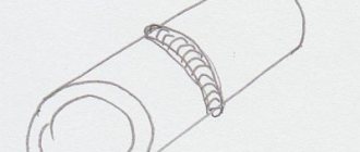
An example of the appearance of a seam after submerged arc welding
The cavity formed during such welding is limited in its upper part by a layer of molten flux, which performs not only a protective function. The molten metal of the electrode and the part being welded, interacting with the flux, undergoes metallurgical processing, which helps to obtain a high-quality weld.
When the arc is removed from a certain welding zone, the molten flux solidifies, forming a hard crust on the finished seam, which is easily removed after the product has cooled. If automatic submerged arc welding is performed, then unused flux is collected from the surface of the part using a special suction device equipped with automated equipment.
In the video, the master explains some of the nuances of welding using flux:
Submerged arc welding, performed both mechanized and automated, has a number of significant advantages.
- The process can be carried out using currents of significant magnitude. As a rule, the current strength when performing such welding is approximately in the range of 1000–2000 Amperes, although it is quite possible to increase this value to 4000 A. For comparison: conventional arc welding is performed with a current strength of no more than 600 A, a further increase in the current strength leads to severe spattering of metal and the inability to form a weld. Meanwhile, increasing the current allows not only to significantly speed up the welding process, but also to obtain a welded joint of high quality and reliability.
- When welding is performed under a layer of flux, a closed arc is formed, which melts the metal of the part to a great depth. Thanks to this, the edges of the part to be welded do not even need to be prepared for their better weldability.
- Since submerged arc welding modes involve the use of high current, the speed of the process increases significantly. If we compare the speed of welding performed under a submerged arc layer, which is measured in the length of the seam obtained over a certain period of time, then it can be 10 times higher than that of conventional arc welding.
- The so-called gas bubble, formed when welding under a protective layer of flux, prevents metal spattering, which makes it possible to obtain high-quality welds. In addition, this significantly reduces the loss of electrode metal, which amounts to a maximum of 2% of the mass of the molten material. In this case, not only electrode material is saved, but also electrical energy.
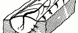
General diagram of submerged arc welding
The choice of welding mode performed under a submerged arc layer is carried out according to the following main parameters:
- diameter of the electrode wire used;
- type of current and its polarity;
- the speed at which welding is performed;
- voltage to form a welding arc.
Additional parameters that influence the determination of the submerged arc welding mode are:
- particle size, composition and density of the flux used;
- value of electrode wire extension;
- a parameter that determines how the electrode and the part being welded are positioned relative to each other.
Welding process
When parts are welded using flux, the arc burns using the original granular powder. The high temperature causes the electrode and surrounding granules to melt. As a result, an elastic film appears that surrounds the welding area .
The film blocks the access of oxygen to the welding arc. The seam is obtained without cracks or cavities. After cooling, the flux turns into slag, uniformly covering the seam. When the operation is completed, the hard crust is removed mechanically. The remaining flux is used for further operations. This “loose blanket” is suitable for work on various equipment.
Types of Granular Powder
To carry out the welding process, flux is divided into several types. It all depends on the metal that will be processed:
- High alloy steel.
- Non-ferrous alloys.
- Carbon and alloy steel.
The production method also divides this granular material into several subtypes:
- Ceramic.
- Melted.
Using the first type allows you to get an improved seam. Fused flux is distinguished by its pumice-like structure.
To obtain ceramic material, special elements are first finely ground. Then mixed with extrusion, which helps to obtain a homogeneous mass. Liquid glass is added to it. This mixture is used only when additional alloying of the welding seam material is required.
After sintering the starting substances and granulating them, a fused flux is obtained. Granules for gas welding are divided into several subgroups. The separation depends on their chemical composition:
- Saline. They contain a large amount of chlorides, as well as a small amount of fluorides. Granules are used for welding active metals. They are used to remelt the remaining slag.
- Mixed. The material is a mixture of salt granules with oxides. Used for working with alloy steels.
- Oxide. The mixture is intended for processing fluorinated steel or low-alloy metal. The composition includes metal oxides coupled with a minimal amount of fluoride compounds.
Important! To get a high-quality seam using automatic welding, you need to choose the right flux.
We'll call you back in 30 seconds.
GOST R ISO 2553-2017 GOST R ISO 6947-2017 GOST R ISO 13920-2017 GOST R 55554-2013 GOST R ISO 6520-1-2012 GOST R ISO 14174-2010 GOST R ISO 14175-2010 GOST R EN 13479-201 0 GOST R EN 12074-2010 GOST R ISO 2560-2009 GOST R 53689-2009 GOST R ISO 3581-2009 GOST R ISO 3580-2009 GOST 10543-98 GOST 19249-73 GOST 21449-75 GOST 5264-80 GOST 9467- 75 GOST 21448 -75 GOST 23178-78 GOST 15164-78 GOST 14806-80 GOST 16038-80 GOST 9087-81 GOST 25445-82 GOST 26271-84 GOST 26101-84 GOST 27580-88 GOST 28915-91 GOST 2246-70 GOST 5.917-71 GOST 5.1215-72 GOST 10051-75 GOST 11533-75 GOST 10052-75 GOST 11534-75 GOST 7871-75 GOST 23518-79 GOST 14776-79 GOST 15878-79 GOST 16037-80 GOST 23949-80 GOST 26467-85 GOST 16130 -90 GOST 30430-96 GOST 30242-97 GOST 30482-97 GOST R 52222-2004 GOST 28555-90 GOST 30756-2001 GOST 14771-76 GOST 9466-75 GOST 8713-79
- gost-8713-79.pdf (923.60 KiB)
GOST 8713-79
GOST 8713−79
Group B05
INTERSTATE STANDARD SUBMERGED WELDING. WELDED CONNECTIONS Main types, structural elements and dimensions of Flux welding. Welded joints. Maih types design elements and dimensions
MKS 25.160.40 OKP 06 0200 0000
Date of introduction 1981−01−01
INFORMATION DATA
1. DEVELOPED by the USSR State Committee for Standards, the Academy of Sciences of the Ukrainian SSR
2. INTRODUCED by the USSR State Committee for Standards
3. APPROVED AND ENTERED INTO EFFECT by Resolution of the USSR State Committee on Standards dated December 26, 1979 N 5047
4. INSTEAD GOST 8713–70
5. REFERENCE REGULATIVE AND TECHNICAL DOCUMENTS
| Designation of the referenced technical document | Item number |
| GOST 11969–93 | 6 |
| GOST 16037–80 | 1 |
6. EDITION (January 2007) with Amendments No. 1, 2, 3, approved in August 1986, January 1989, July 1990 (IUS 11−86, 4−89, 10−90) AMENDED , published in IMS No. 6, 2007 Amendment made by the database manufacturer
1. This standard applies to joints made of steels, as well as alloys on iron-nickel and nickel bases, performed by submerged arc welding, and establishes the main types, structural elements and dimensions of welded joints. The standard does not apply to welded joints of steel pipelines in accordance with GOST 16037.
2. The standard adopts the following designations for submerged arc welding methods: AF - automatic on weight; AFf - automatic on a flux pad; AFm - automatic with flux-copper lining; AFo - automatic on the remaining lining; AFp - automatic on a copper slide; AFsh - automatic with preliminary application of a weld seam; AFk - automatic with preliminary welding of the weld root; MF - mechanized on weight; MFO - mechanized on the remaining lining; MFsh - mechanized with preliminary application of a weld seam; MFk - mechanized with preliminary welding of the root of the seam. (Changed edition, Amendment No. 2).
3. The main types of welded joints are given in Table 1; the sections of pre-applied welds are conventionally blackened.
Table 1
| Cross-sectional shape | |||||||
| Connection type | Shape of prepared edges | Character of the weld | prepared edges | weld | Welding method | Thickness of welded parts, mm | Symbol of welded joint |
| Butt | With beaded edges | Single sided | AF; MF | 1,5−3,0 | C1 | ||
| No beveled edges | 2,0−12,0 | C47 | |||||
| AFf | 2,0−10,0 | C4 | |||||
| AFm | 3,0−12,0 | ||||||
| AFp | 5,0−20,0 | ||||||
| AFo; MFO | 2,0 -12,0 | C5 | |||||
| Double-sided | AF; MF | 2,0−20,0 | C7 | ||||
| AFsh; MFsh | 2,0−12,0 | ||||||
| AFf | 2,0−32,0 | S29 | |||||
| No bevel of edges followed by gouging | 16,0−32,0 | C30 | |||||
| With one edge beveled | Single sided | AFf | 8,0−20,0 | C9 | |||
| AFm | |||||||
| AFo; MFO | 8,0−30,0 | C10 | |||||
| AFo | C11 | ||||||
| Double-sided | AF | 14,0−20,0 | C12 | ||||
| With a curved bevel of one edge | Single sided | AFf | 16,0−50,0 | C31 | |||
| With a broken bevel on one edge | AFf | C32 | |||||
| With two symmetrical bevels on one edge | Double-sided | AF | 20,0−30,0 | C15 | |||
| With beveled edges | Single sided | AFf | 8,0−24,0 | C18 | |||
| AFm | 12,0−30,0 | ||||||
| AFo; MFO | 8,0−30,0 | C19 | |||||
| Single-sided locking | AFo | S20 | |||||
| Double-sided | AF; MF | 14,0−30,0 | S21 | ||||
| AFk; MFK | |||||||
| AFsh; MFsh | 5,0−14,0 | ||||||
| AFf | 14,0−30,0 | C33 | |||||
| With curved edges | Single sided | AFo | 16,0−60,0 | C34 | |||
| Single-sided locking | 16,0−50,0 | S35 | |||||
| Double-sided | AFk | 24,0−160,0 | S23 | ||||
| With broken bevel edges | Single sided | AFf | 20,0−60,0 | C36 | |||
| With broken bevel edges | Single-sided locking | AFo | 16,0−60,0 | C37 | |||
| With two symmetrical edge bevels | Double-sided | AF; MF | 18,0−60,0 | S25 | |||
| AFk | 24,0−60,0 | S25 | |||||
| AFf | 18,0−60,0 | C38 | |||||
| With two asymmetrical edge bevels | AFsh; MFsh | 16,0−60,0 | C39 | ||||
| With two symmetrical curved edge bevels | AF | 50,0−160,0 | S26 | ||||
| With two asymmetrical edge bevels | A Fsh | 24,0−130,0 | C40 | ||||
| 24,0−60,0 | C41 | ||||||
| Angular | With flange on one edge | Single sided | AF; MF | 1,5−3,0 | U1 | ||
| No beveled edges | Double-sided | AFsh; MFsh | 4,0−14,0 | U5 | |||
| With one edge beveled | Double-sided | AFsh; MFsh | 8,0−20,0 | U7 | |||
| With two asymmetrical edge bevels | 20,0−40,0 | U3 | |||||
| Tavrovoe | No beveled edges | Single sided | AF; MF | 3,0−40,0 | T1 | ||
| Double-sided | T3 | ||||||
| AFsh; MFsh | 3,0−20,0 | T3 | |||||
| With one edge beveled | AFsh; MFsh | 8,0−30,0 | T7 | ||||
| With a curved bevel of one edge | AFsh | 16,0−30,0 | T2 | ||||
| With two symmetrical bevels on one edge | AF; MF | 16,0−40,0 | T8 | ||||
| With two asymmetrical bevels on one edge | AFsh; MFsh | 20,0−40,0 | T4 | ||||
| With two symmetrical curved bevels on one edge | AF | 30,0−60,0 | T5 | ||||
| Overlapping | No beveled edges | Single sided | AF; MF | 1,0−20,0 | H1 | ||
| Double-sided | H2 | ||||||
(Changed edition, Amendment No. 2, 3).
4. Structural elements of welded joints and their dimensions must correspond to those indicated in Table 2−52, sections of pre-applied welds are conditionally blackened.
table 2
Dimensions, mm
| Symbol of welded joint | Structural elements | Welding method | ||||
| prepared edges of welded parts | weld | |||||
| C1 | AF; MF | 1,5−3,0 | -1,5 | -3 | ||
| ________________ * Size for reference. | ||||||
Table 3
Dimensions, mm
| Symbol of welded joint | Structural elements | Welding method | , no more | ||||||
| prepared edges of welded parts | weld | No-min. | Prev. off | No-min. | Prev. off | ||||
| C47 | Af; Mf | 2 | 0 | +0,3 | 8,5 | 1,5 | ±1,0 | ||
| St. 2 to 3 | +0,5 | 10 | |||||||
| St. 3 to 4 | +0,8 | 12 | 2,0 | +1,0 -1,5 | |||||
| St. 4 to 5 | 14 | ||||||||
| St. 5 to 6 | |||||||||
| St. 6 to 8 | +1,0 | 16 | |||||||
| St. 8 to 10 | 19 | ||||||||
| St. 10 to 12 | 21 | ||||||||
| Note. The MF welding method for <3 mm is not recommended. | |||||||||
Table 4
Dimensions, mm
| Symbol of welded joint | Structural elements | Welding method | , no more | ||||||||
| prepared edges | weld | No-min. | Prev. off | No-min. | Prev. off | No-min. | Prev. off | ||||
| C4 | AFf | 2 | 0,0 | +1,0 | 12 | 1,5 | ±1,0 | 1,0 | ±1,0 | ||
| St. 2 to 3 | 1,0 | ±1,0 | |||||||||
| St. 3 to 4 | 16 | 2,0 | +1,0 -1,5 | 1,5 | +1,0 -1,5 | ||||||
| St. 4 to 5 | 1,5 | ||||||||||
| St. 5 to 6 | 21 | ||||||||||
| St. 6 to 7 | 2,0 | ±1,5 | 2,0 | +1,0 -2,0 | |||||||
| St. 7 to 10 | 26 | ||||||||||
| Note. It is allowed that there is no convexity on the reverse side of the seam and local concavities with a depth of no more than 0.1 with complete penetration of the edges. The value should be between 4 mm and 0.5. | |||||||||||
Table 5
Dimensions, mm
| Symbol of welded joint | Structural elements | Welding method | , no more | ||||||
| prepared edges of welded parts | weld | No-min. | Prev. off | No-min. | Prev. off | ||||
| C4 | AFm | 3 | 1,0 | +0,5 | 14 | 1,5 | +1,0 -1,5 | ||
| 4 | 16 | ||||||||
| St. 4 to 5 | 1,5 | ±1,0 | |||||||
| St. 5 to 6 | 21 | ||||||||
| St. 6 to 7 | 2,0 | 2,0 | +1,0 -2,0 | ||||||
| St. 7 to 10 | 26 | ||||||||
| St. 10 to 12 | 4,0 | 28 | |||||||
| Note. It is allowed that there is no convexity on the reverse side of the seam and local concavities with a depth of no more than 0.1 with complete penetration of the edges. The value should be between 4 mm and 0.5 . | |||||||||
Table 6
Dimensions, mm
| Symbol of welded joint | Structural elements | Welding method | ±4 | , no more | ||||||
| prepared edges of welded parts | weld | No-min. | Prev. off | No-min. | Prev. off | |||||
| AFp | 5−6 | 12 | 23 | 3 | +2 | 1,5 | ±1,0 | |||
| C4 | 7−10 | 14 | 26 | 4 | +1,5 -1,0 | |||||
| 12−14 | 28 | |||||||||
| 16−18 | 16 | 36 | 5 | 2,0 | ±1,5 | |||||
| 20 | 38 | 6 | ||||||||
| Note. It is allowed that there is no convexity on the reverse side of the seam and local concavities with a depth of no more than 0.1 with complete penetration of the edges. | ||||||||||
Table 7
Dimensions, mm
| Symbol of welded joint | Structural elements | Welding method | , no less | , no more | ||||||
| prepared edges of welded parts | weld | No-min. | Prev. off | No-min. | Prev. off | |||||
| C5 | AFo; MFO | 2 | 1,5 | ±1,0 | 15 | 12 | 1,5 | ±1,0 | ||
| St. 2 to 3 | 17 | |||||||||
| St. 3 to 4 | 2,0 | 2,0 | +1,0 -1,5 | |||||||
| St. 4 to 5 | 20 | |||||||||
| St. 5 to 6 | 3,0 | ±1,5 | 21 | |||||||
| St. 6 to 7 | 25 | |||||||||
| St. 7 to 8 | 26 | |||||||||
| St. 8 to 10 | 4,0 | 30 | ||||||||
| St. 10 to 12 | 5,0 | 28 | ||||||||
| Note. The MFO welding method for >6 mm is not recommended. The thickness of the lining must be at least 0.25, but not less than 1.5 mm. | ||||||||||
Table 8
Dimensions, mm
| Symbol of welded joint | Structural elements | Welding method | , no more | ||||||
| prepared edges of welded parts | weld | No-min. | Prev. off | No-min. | Prev. off | ||||
| C7 | AF; MF | 2 | 0 | +0,3 | 8,5 | 1,5 | ±1,0 | ||
| St. 2 to 3 | +0,5 | 10 | |||||||
| St. 3 to 4 | +0,8 | 12 | 2,0 | +1,0 -1,5 | |||||
| St. 4 to 5 | +1,0 | 14 | |||||||
| St. 5 to 6 | 19 | ||||||||
| St. 6 to 9 | ±1,5 | ||||||||
| St. 9 to 14 | 23 | 3,0 | +1,5 -2,0 | ||||||
| St. 14 to 20 | 28 | ±2,0 | |||||||
| Note. The MF welding method for >6 mm is not recommended. | |||||||||
Table 9
Dimensions, mm
| Symbol of welded joint | Structural elements | Welding method | , no more | ±2 | ||||||
| prepared edges of welded parts | weld | No-min. | Prev. off | No-min. | Prev. off | |||||
| C7 | AFsh; MFsh | 2 | 0,5 | +0,5 | 8,5 | 8 | 1,5 | ±1,0 | ||
| St. 2 to 3 | 1,0 | ±1,0 | 10 | |||||||
| St. 3 to 4 | 12 | 2,0 | +1,0 -1,5 | |||||||
| St. 4 to 5 | 14 | 10 | ||||||||
| St. 5 to 7 | 1,5 | +1,0 -1,5 | 16 | 12 | ||||||
| St. 7 to 12 | 2,0 | +1,0 -2,0 | 19 | 14 | 3,0 | +1,0 -2,0 | ||||
| Note. The MFsh welding method is not recommended for thicknesses of 3 mm–6 mm. | ||||||||||
Table 10
Dimensions, mm
| Symbol of welded joint | Structural elements | Welding method | , no more | |||||
| prepared edges of welded parts | weld | No-min. | Prev. off | No-min. | Prev. off | |||
| S29 | AFf | 2 | 0 | +1 | 8,5 | 1,5 | ±1,0 | |
| St. 2 to 3 | 1 | ±1 | 10 | +1,0 -1,5 | ||||
| St. 3 to 5 | 12 | 2,0 | ||||||
| St. 5 to 6 | 19 | |||||||
| St. 6 to 9 | 2 | |||||||
| St. 9 to 10 | 24 | +1,0 -2,0 | ||||||
| St. 10 to 14 | 2,5 | |||||||
| St. 14 to 16 | 26 | ±2,0 | ||||||
| St. 16 to 22 | 4 | +1 -2 | 34 | |||||
| St. 22 to 26 | 5 | +1 -2 | 40 | 3,0 | +2,0 -2,5 | |||
| St. 26 to 30 | 6 | +2 -1 | 42 | +2,0 -3,0 | ||||
| AFf* | From. 6 to 9 | 3 | ±1 | 22 | 2,5 | ±1,5 | ||
| St. 9 to 16 | 4 | 26 | ||||||
| St. 16 to 24 | 5 | ±1,5 | 34 | |||||
| St. 24 to 32 | 6 | 40 | 3 | ±2 | ||||
____________________ * Before welding the first seam, the gap must be filled to 1/3 of the thickness of the base metal with flux, and then to the remaining 2/3 with grit from electrode wire, pellets or other granular metal.
Table 11
Dimensions, mm
| Symbol of welded joint | Structural elements | Welding method | ±1 | ±2 | , no more | |
| prepared edges of welded parts | weld | |||||
| C30 | AFf | From 16 to 22 | 8 | 9 | 18 | |
| St. 22 to 26 | 13 | 14 | 24 | |||
| St. 26 to 32 | 18 | 18 | 28 | |||
Table 12
Dimensions, mm
| Symbol of welded joint | Structural elements | Welding method | |||||
| prepared edges of welded parts | weld | No-min. | Prev. off | No-min. | Prev. off | ||
| C9 | AFf; AFm | 8 to 9 | 18 | ±3 | ±1,0 | ||
| St. 9 to 10 | 20 | ±4 | 1,5 | ||||
| St. 10 to 14 | 22 | 2,0 | +1,0 -1,5 | ||||
| St. 14 to 20 | 24 | 2,5 | +1,0 -2,0 | ||||
Note. It is allowed that there is no convexity on the reverse side of the seam and local concavities with a depth of no more than 0.1 with complete penetration of the edges.
Table 13
Dimensions, mm
| Symbol of welded joint | Structural elements | Welding method | , no less | , no less | |||||||
| prepared edges of welded parts | weld | No-min. | Prev. off | No-min. | Prev. off | No-min. | Prev. off | ||||
| C10 | AFo; MFO | 8 | 2 | ±1,0 | 3 | 25 | 18 | ±3 | 1,5 | ±1,0 | |
| St. 8 to 10 | 20 | ||||||||||
| St. 10 to 12 | 22 | ±4 | 2,0 | +1,0 -1,5 | |||||||
| St. 12 to 14 | 3 | ±1,5 | 4 | ||||||||
| St. 14 to 16 | 24 | 2,5 | +1,0 -2,0 | ||||||||
| St. 16 to 18 | 4 | 30 | |||||||||
| St. 18 to 20 | 6 | ||||||||||
| St. 20 to 24 | 5 | 26 | +1,5 -2,0 | ||||||||
| St. 24 to 30 | 40 | 30 | |||||||||
Table 14
Dimensions, mm
| Symbol of welded joint | Structural elements | Welding method | |||||||
| prepared edges of welded parts | weld | No-min. | Prev. off | No-min. | Prev. off | No-min. | Prev. off | ||
| C11 | AFo | 8 | 2 | ±1,0 | 18 | ±3 | 1,5 | +1,0 | |
| St. 8 to 10 | 20 | ||||||||
| St. 10 to 12 | 22 | ±4 | 2,0 | +1,0 -1,5 | |||||
| St. 12 to 14 | 3 | ±1,5 | |||||||
| St. 14 to 16 | 24 | 2,5 | +1,0 -2,0 | ||||||
| St. 16 to 20 | 4 | ||||||||
| St. 20 to 24 | 5 | 26 | +1,5 -2,0 | ||||||
| St. 24 to 30 | 30 | ||||||||
Table 15
Dimensions, mm
| Symbol of welded joint | Structural elements | Welding method | |||||
| prepared edges of welded parts | weld | No-min. | Prev. off | No-min. | Prev. off | ||
| C12 | AF | 14 | 18 | ±3 | 2,0 | +1,0 -1,5 | |
| St. 14 to 16 | 2,5 | +1,0 -2,0 | |||||
| St. 16 to 20 | 22 | ±4 | |||||
Table 16
Dimensions, mm
| Symbol of welded joint | Structural elements | Welding method | |||||
| prepared edges of welded parts | weld | No-min. | Prev. off | No-min. | Prev. off | ||
| C31 | AFf | 16 | 19 | ±2 | 2,0 | +1,0 -2,0 | |
| St. 16 to 20 | 20 | ||||||
| St. 20 to 25 | 22 | ||||||
| St. 25 to 30 | 23 | ±3 | |||||
| St. 30 to 35 | 25 | ||||||
| St. 35 to 40 | 26 | ±4 | |||||
| St. 40 to 45 | 28 | +1,5 -2,0 | |||||
| St. 45 to 50 | 30 | ||||||
Table 17
Dimensions, mm
| Symbol of welded joint | Structural elements | Welding method | |||||
| prepared edges of welded parts | weld | No-min. | Prev. off | No-min. | Prev. off | ||
| C32 | AFf | 16 | 19 | ±3 | 2,5 | +1,0 -2,0 | |
| St. 16 to 20 | 20 | ||||||
| St. 20 to 25 | 21 | ||||||
| St. 25 to 30 | 22 | ||||||
| St. 30 to 35 | 23 | ||||||
| St. 35 to 40 | 24 | ±4 | |||||
| St. 40 to 45 | 25 | +1,5 -2,0 | |||||
| St. 45 to 50 | 26 | ||||||
Table 18
Dimensions, mm
| Symbol of welded joint | Structural elements | Welding method | |||
| prepared edges of welded parts | weld | Nom. | Prev. off | ||
| C15 | AF | From 20 to 24 | 22 | ±3 | |
| St. 24 to 28 | 26 | ±4 | |||
| St. 28 to 30 | 30 | ||||
Table 19
Dimensions, mm
| Symbol of welded joint | Structural elements | Welding method | ±1 | |||||
| prepared edges of welded parts | weld | No-min. | Prev. off | No-min. | Prev. off | |||
| C18 | AFf | 8 to 9 | 3 | 18 | ±3 | 1,5 | ±1,0 | |
| St. 9 to 10 | 20 | |||||||
| St. 10 to 12 | 22 | ±4 | 2,0 | +1,0 -1,5 | ||||
| St. 12 to 14 | 4 | |||||||
| St. 14 to 20 | 24 | 2,5 | +1,0 -2,0 | |||||
| St. 20 to 24 | 26 | ±5 | ||||||
Positive characteristics
To implement this technology, welding current is supplied to the wire through a special mouthpiece. It is located approximately 70 mm from the edge. In this case, the electrode cannot overheat. High current can be used for operation. The result is fast surfacing and good deep penetration. Very thick metal can be welded without first cutting the edges.
When automatic arc welding is performed, a constant seam size is maintained. It turns out to be the same shape and has a homogeneous chemical composition. The result is a high-quality connection that is highly stable. This technology prevents the appearance of defects associated with the appearance of undercuts and metal fusion.
Flux protects against splashing. The surrounding surface will not need to be cleaned of welding spatter.
Flux welding is considered a high-performance process, which significantly saves energy, together with welding materials. Savings reach 30-40%.
Thickness of welded parts
This is an important parameter that determines the choice of one technology or another, the method and specific shape of edge cutting, the number of sides of the seam and the number of passes. Thin workpieces (up to 1 mm) are welded using the “flanging” cutting technique . It allows you to avoid burn-through, increase the contact area of the workpieces and increase the strength, durability and tightness (if necessary) of the connection. Workpieces from 1 to 4 mm are welded without cutting edges.
The small thickness allows for complete penetration and high quality seams. Workpieces thicker than 4 mm are edge-cut. This is necessary to ensure access of the electrode to the root of the seam to achieve complete and high-quality penetration.
For parts thicker than 60 mm, special cutting profiles are used, various curved or stepped, and the seam is welded in several passes . GOST also regulates welding mixtures depending on thickness.
Single-sided automatic submerged butt welding technology
Single-sided welding is used when welding minor metal structures, or in cases where it is not possible to perform double-sided welding due to design features.
Features of one-sided butt welding are a large amount of liquid metal, a large penetration depth and overheating of the weld pool. All this can cause liquid metal to leak out through the gaps and disrupt the formation of the weld. In order to prevent this, it is necessary to weld the joint from the reverse side, thus closing the gap, or to cover the reverse side of the seam with a metal (copper or steel) backing, or to close this gap from the reverse side with a layer of flux.
There are four most common methods for one-sided automatic welding of butt seams, which allow you to make a weld of the required configuration and obtain high quality welding. Let's consider these methods in more detail.
Automatic flux-cored welding technology
Variants of this welding method are shown in the figure on the right. The essence of this type of welding is that under the parts to be welded, pos. 1, a layer of flux, pos. 2, is placed, the thickness of which is 30-50 mm. The flux pad fits tightly to the edges to be welded and is pressed against them as a result of the influence of the own weight of the parts being welded, or through a rubber hose containing air. The air pressure in the hose depends on the thickness of the metal being welded and is 0.05-0.06 MPa when welding thin metal and 0.2-0.25 MPa when welding thick metal. The flux layer prevents leakage of liquid metal through the gap and ensures good formation of the weld and high quality welding. Approximate modes of automatic single-sided butt welding performed on a flux layer are presented in the table below:
| Current strength, A | Wire feed speed, m/h | Arc voltage, V | Welding speed, m/h | ||
| 10 | 3-4 | 700-750 | 62 | 34-36 | 30 |
| 12 | 4-5 | 750-800 | 67 | 36-40 | 27 |
| 14 | 4-5 | 850-900 | 78 | 36-40 | 25 |
| 16 | 5-6 | 900-950 | 84 | 38-42 | 20 |
| 18-20 | 5-6 | 950-1000 | 92 | 40-44 | 15-17 |
Copper pad automatic welding technology
The use of automatic submerged arc welding technology on copper pads makes it possible to improve heat removal from the welded edges and avoid metal burnout. In addition, the copper backing bridges the gap between the welded edges and prevents liquid metal from flowing through it.
The lining fits tightly from below to the edges to be welded and is pressed against them using special devices. After the metal welding process is completed, the copper lining is easily separated from the steel edges. If the gap between the parts being welded exceeds 2 mm, a groove is made in the copper lining, which is filled with welding flux. With this technology, a weld bead is formed on the reverse side of the welded edges. Typically, the width of the copper lining is 40-60mm, and its thickness is determined by the thickness of the welded edges and can be in the range of 5-30mm.
There is also a welding method developed by the E.O. Paton Welding Institute, in which a copper shoe, which is cooled with water, moves along the reverse side of the welded edges, parallel to the movement of the electrode. Such a diagram is shown in the figure on the right. With this automatic welding technology, the parts to be welded are assembled with a gap of 2-3 mm and fastened at a distance of 1.2-1.5 m with short strips, which are secured with short seams.
The welding tractor, pos. 2, has a knife, pos. 5, which is installed in the joint gap and presses the rod, pos. 4, with the rollers, pos. 6, and the copper shoes, pos. 3, using the spring, pos. 1, to the underside of the products being welded. The shoe moves with the welding tractor and prevents molten metal from flowing out through the gaps.
Automatic welding technology on steel pads
The technology of automatic submerged arc welding using steel pads is used in cases where it is structurally possible to weld the pads on the reverse side. The steel backing is pressed tightly against the parts to be welded from below and welded with short tacks using manual arc welding.
Then the butt seam and, along with it, the metal of the steel lining are welded using automatic welding. The width of such a lining is 20-60mm, the thickness is in the range of 4-6mm, and the length is equal to the length of the weld.
Automatic submerged arc welding when performing a back-up bead
The technology of automatic welding of butt joints with the execution of a back-up weld is used in cases where it is necessary to facilitate the assembly of welded parts for welding. But this method has not found wide application in industry due to the high labor intensity of this welding method. In addition, the consumption of materials increases, which is also not profitable from an economic point of view.
Edge preparation form
GOST 8713-79, which describes gas-shielded welding and welded joints, requires high precision when cutting the edges of workpieces . The accuracy requirements for conventional manual MMA or argon arc welding are noticeably lower. An automatic welding machine is adjusted to a specific welding mode, including current strength, distance from the workpiece to the electrode and its trajectory.
During the execution of the programmed program, the automatic device will not be able to take into account inaccuracies in processing or installation of the workpiece, as a qualified and experienced welder could do.
Edge cutting is carried out using gas, plasma or laser cutting machines. Metalworking machines (milling, planing, slotting) are also used. Less commonly used for cutting are water cutting installations.
Before starting work, it is necessary to carry out preparation: clean from mechanical impurities, slag, rust, oil and fat stains . The remaining contaminants, once within the arc's action zone, lead to the formation of such defects as:
- pores and cavities;
- cracks;
- lack of penetration;
- foreign non-metallic inclusions.
Mechanical cleaning is carried out using sandblasting or manual angle grinders. Chemical passivation is also used for better removal of the oxide film. In addition to the edges themselves, the heat-affected area is also cleaned 5-6 mm on each side of the seam. General degreasing with organic solvents or inorganic active substances covers the same area.
The workpieces must be securely secured to the assembly stand using clamps or special equipment. Tacking in predetermined places by manual electrode welding or in a carbon dioxide environment is also used. Point tacks are made from strips of metal 5-7 cm long. They are installed no further than 40 cm from one another, at the edge they should be no further than 20 cm from the beginning (end) of the seam. They must be cleaned of melt splashes and slags.
To enter and exit the electrode without burning through, inlet and outlet pads are installed at the beginning and end of the seam, cut with the same profile as the main seam.
Operating modes are selected based on the metal of the workpieces, their thickness, and type of cutting. These include:
- operating current and voltage;
- thickness and rate of supply of welding material;
- speed and inclination of electrode movement.
Butt seams are welded with or without groove . The connection can be welded on one or both sides, as well as in several passes.
An example of the main GOST table for connection type C18.
If it is possible to bring the gap between the workpieces to 1 mm, then work in the “boat” position is carried out without a lining. If the gap is larger, a metal or asbestos plate is placed, or a cushion of flux is added. Preliminary welding of the root of the seam from the inside is also used.
Welding in the boat position is recommended for fillet and T welds . It makes it possible to evenly melt the edges and increase the cross-sectional area of the seam. To do this, the workpieces are secured in a special rotary equipment called a tilter. It can rotate together with the workpiece around a longitudinal axis parallel to the seam line. GOST provides for the assembly of a welded I-beam in the same way.
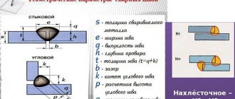
Welding diagrams.
Welding of T-joints and overlap welds is carried out with an angle of inclination of the electrode of 15-30° to the seam line. The disadvantages of this method include the limitation of the maximum leg value of 16 millimeters. To obtain large values, it is necessary to resort to multi-pass boiling.
Features of submerged arc welding according to GOST 8713-79
When the welding process occurs, due to the oxygen environment, the surface of the parts being welded begins to oxidize. To obtain high-quality welding of some metals, it is necessary to use special additives. In order to protect the weld pool, cleaned wire is used. The operation is carried out using inert gas. The current GOST 8713–79 regulates submerged arc welding and the use of material to obtain a high-quality seam.
- Advantages of flux welding
- Welding process
- Types of Granular Powder
- Positive characteristics
- Negative sides
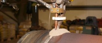
Equipment used for submerged arc welding
Let's take a look at existing submerged arc welding equipment. When it comes to carrying out welding work in a production workshop, before starting the welding process, the parts to be welded are securely fixed on a special assembly stand or using other devices in order to completely eliminate possible unplanned movements of the elements being welded during work.
Welding tractor (manufacturer: Multitrac)
When laying pipelines, special mobile welding heads are mainly used for welding joints, and in the production of sheet structures, either stationary installations or universal mobile ones (for example, a welding tractor) are used. The submerged arc welding tractor is a self-propelled trolley with an electric motor on which an automatic welding head is installed. Such a device can move along the parts being welded along a rail track or directly along the parts themselves.
Welding column and welded part on roller supports
In workshop conditions, mobile or stationary welding columns are also actively used, which, in combination with roller bearings or rotators, are used for welding longitudinal and circumferential seams.
Advantages of flux welding
The emergence of the technological process of welding using flux can be compared with a revolution in the industrial sector.
This technology was first used to process low-carbon steel. Today, this powder is used for welding absolutely any, even very refractory metals that are difficult to weld.
Mechanized equipment and various semi-automatic systems allow the use of flux for various operations:
- Formation of a vertical seam. Welding sheet metal with a thickness of 20-30 mm is considered the most durable.
- Pipe connection. The machines initially welded small-diameter pipes. Today, after improvements in technology, it has become possible to process large diameter products.
- Obtaining a circular seam. The welding process is complicated by holding the weld pool while preventing the metal from spreading. This welding is performed on machines equipped with CNC (Computer Numerical Control). Sometimes additional manual welding is carried out.
Welding process
When parts are welded using flux, the arc burns using the original granular powder. The high temperature causes the electrode and surrounding granules to melt. As a result, an elastic film appears that surrounds the welding area .
The film blocks the access of oxygen to the welding arc. The seam is obtained without cracks or cavities. After cooling, the flux turns into slag, uniformly covering the seam. When the operation is completed, the hard crust is removed mechanically. The remaining flux is used for further operations. This “loose blanket” is suitable for work on various equipment.
Types of Granular Powder
To carry out the welding process, flux is divided into several types. It all depends on the metal that will be processed:
- High alloy steel.
- Non-ferrous alloys.
- Carbon and alloy steel.
The production method also divides this granular material into several subtypes:
- Ceramic.
- Melted.
Using the first type allows you to get an improved seam. Fused flux is distinguished by its pumice-like structure.
To obtain ceramic material, special elements are first finely ground. Then mixed with extrusion, which helps to obtain a homogeneous mass. Liquid glass is added to it. This mixture is used only when additional alloying of the welding seam material is required.
After sintering the starting substances and granulating them, a fused flux is obtained. Granules for gas welding are divided into several subgroups. The separation depends on their chemical composition:
- Saline. They contain a large amount of chlorides, as well as a small amount of fluorides. Granules are used for welding active metals. They are used to remelt the remaining slag.
- Mixed. The material is a mixture of salt granules with oxides. Used for working with alloy steels.
- Oxide. The mixture is intended for processing fluorinated steel or low-alloy metal. The composition includes metal oxides coupled with a minimal amount of fluoride compounds.
Important! To get a high-quality seam using automatic welding, you need to choose the right flux.
Positive characteristics
To implement this technology, welding current is supplied to the wire through a special mouthpiece. It is located approximately 70 mm from the edge. In this case, the electrode cannot overheat. High current can be used for operation. The result is fast surfacing and good deep penetration. Very thick metal can be welded without first cutting the edges.
When automatic arc welding is performed, a constant seam size is maintained. It turns out to be the same shape and has a homogeneous chemical composition. The result is a high-quality connection that is highly stable. This technology prevents the appearance of defects associated with the appearance of undercuts and metal fusion.
Flux protects against splashing. The surrounding surface will not need to be cleaned of welding spatter.
Flux welding is considered a high-performance process, which significantly saves energy, together with welding materials. Savings reach 30-40%.
Automatic submerged arc welding GOST 8713 79
8
Official dealer, volume discounts, Large assortment, guaranteed delivery on time, Own warehouses in Russia, energetic team, Close-knit team of TeploCity - your success!
- About company
- To the installer
- Services
- Certificates
- Price list
- Contacts
- Vacancies
- Specialist. offers
- New items
- Sale
- Normal documentation
- Clients
- Objects
- Selection
- Convert DN to inches
- Calculator standard
- Conversion of pressure units
- Power transfer
- Temperature conversion
Pressure Converter
Power unit converter
Convert DN to inches
| DN (Du), mm. | Inches |
| DN (Dn) = 10 | 3/8″ |
| DN (Dn) = 15 | 0,5″ |
| DN (Dn) = 20 | 3/4″ |
| DN (Dn) = 25 | 1″ |
| DN (Dn) = 32 | 1,25″ |
| DN (Dn) = 40 | 1,5» |
| DN (Dn) = 50 | 2″ |
| DN (Dn) = 65 | 2,5″ |
| DN (Dn) = 80 | 3″ |
| DN (Dn) = 90 | 3,5″ |
| DN (Dn) = 100 | 4″ |
| DN (Dn) = 125 | 5″ |
| DN (Dn) = 150 | 6″ |
| DN (Dn) = 175 | 7″ |
| DN (Dn) = 200 | 8″ |
| DN (Dn) = 225 | 9″ |
| DN (Dn) = 250 | 10″ |
| DN (Dn) = 275 | 11″ |
| DN (Dn) = 300 | 12″ |
| DN (Dn) = 350 | 14″ |
| DN (Dn) = 400 | 16″ |
| DN (Dn) = 450 | 18″ |
| DN (Dn) = 500 | 20″ |
| DN (Dn) = 550 | 22″ |
| DN (Dn) = 600 | 24″ |
| DN (Dn) = 700 | 28″ |
| DN (Dn) = 800 | 32″ |
| DN (Dn) = 900 | 36″ |
| DN (Dn) = 1000 | 40″ |
| DN (Dn) = 1050 | 42″ |
| DN (Dn) = 1100 | 44″ |
| DN (Dn) = 1200 | 48″ |
| DN (Dn) = 1300 | 52″ |
| DN (Dn) = 1400 | 56″ |
| DN (Dn) = 1500 | 60″ |
| DN (Dn) = 1600 | 64″ |
| DN (Dn) = 1700 | 68″ |
| DN (Dn) = 1800 | 72″ |
| DN (Dn) = 1900 | 76″ |
| DN (Dn) = 2000 | 80″ |
| DN (Dn) = 2200 | 88″ |
- Water supply
- Steam supply
- Food Industry
- Heat supply
- Gas supply and petrochemicals
Equipment Manufacturers
| Ball valves, gate valves and butterfly valves: Naval, Genebre, KMC from » Library » GOST standards for hardware » GOST 8713-79 - Submerged arc welding. Welded connections Main types, structural elements and dimensions. |
GOST 8713-79
INTERSTATE STANDARD
Submerged arc welding. Welded connections
Main types, structural elements and dimensions
Publishing house of standards Moscow
Interstate standard
Submerged arc welding. Welded connections
Main types, structural elements and dimensions
Flux welding. Welded joints. Maih types design elements and dimensions
Download the full text of the document: gost-8713-79.pdf
GOST 8713-79
Date of introduction 01/01/81
1. This standard applies to joints made of steels, as well as alloys on iron-nickel and nickel bases, performed by submerged arc welding, and establishes the main types, structural elements and dimensions of welded joints.
GOST 8713-79
5. When welding circumferential seams of butt joints, it is allowed to increase the convexity g ,
g
1 up to 30%.
(Changed edition, Amendment No. 3).
6. Welded joints T7, T8, T4 should be made in the “boat” position in accordance with GOST 11969-79.
Fillet welds without beveled edges can be made both in the lower position and in the “boat” position according to GOST 11969-79.
7. Back welding and weld root welding can be performed using any arc welding method.
8. Welding butt joints of parts of unequal thickness with a difference not exceeding the values indicated in the table. 53, must be produced in the same way as parts of the same thickness; the structural elements of the prepared edges and the dimensions of the weld should be selected according to their greater thickness.
Table 53
mm
| Thickness of thin part | Part thickness difference |
| From 2 to 4 | 1 |
| St 4 » 30 | 2 |
| » 30 » 40 | 4 |
| » 40 | 6 |
To achieve a smooth transition from one part to another, an inclined position of the seam surface is allowed (Fig. 1).
Crap. 1
If the difference in the thickness of the parts being welded exceeds the values indicated in the table. 53, on a part with a large thickness s
1, a bevel must be made on one or both sides to the thickness of the thin part
s
, as indicated in Fig. 2, 3 and 4. In this case, the structural elements of the prepared edges and the dimensions of the weld should be selected based on their smaller thickness.
Crap. 2
Crap. 3
Crap. 4
9. Size and maximum deviations of fillet weld leg K
,
K
1 must be installed during design. In this case, the leg size should be no more than 3 mm for parts with a thickness of up to 3 mm inclusive, and 1.2 times the thickness of a thinner part when welding parts with a thickness of over 3 mm. The maximum deviations of the fillet weld leg size from the nominal value are given in Appendix 3.
(Changed edition, Amendment No. 2).
10. (Deleted, Amendment No. 2).
11. Convexity or concavity of a fillet weld up to 30% of its leg is allowed. In this case, concavity should not lead to a decrease in the value of leg K
n (Fig. 5), installed during design.
Crap. 5
Note. Side K
n is the leg of the largest right triangle inscribed in the outer part of the fillet weld.
With a symmetrical seam,
any of the equal legs is taken K
12. The minimum values of fillet weld legs are given in recommended Appendix 1.
13. When using submerged arc welding instead of manual arc welding, the leg of the fillet weld of the design connection can be reduced to the values given in recommended Appendix 2.
14. It is allowed to mix the welded edges before welding relative to each other no more than:
0.5 mm - for parts up to 4 mm thick;
1.0 mm - for parts with a thickness of 4-10 mm;
0.1 s mm, but not more than 3 mm - for parts with a thickness of more than 10 mm.
15. In places where welds overlap and where defects are corrected, it is allowed to increase the size of seams up to 30% of the nominal value.
16. When preparing edges using hand tools, the maximum deviations of the edge bevel angle can be increased to ±5°. In this case, the width of the seam can be changed accordingly, e
,
e
1
.
15, 16. (Introduced additionally, Amendment No. 2).
ANNEX 1
Recommended
mm
| Yield strength of welded steel, MPa | Minimum value of fillet weld legs for a welded element of greater thickness | |||||||
| from 3 to 4 | St. 4 to 5 | St. 5 to 10 | St. 10 to 16 | St. 16 to 22 | St. 22 to 32 | St. 32 to 40 | St. 40 to 80 | |
| Up to 400 | 3 | 3 | 4 | 5 | 6 | 7 | 8 | 9 |
| St. 400 to 450 | 3 | 4 | 5 | 6 | 7 | 8 | 9 | 10 |
Note. The maximum value of the legs should not exceed 1.2 times the thickness of the thinner element.
(Changed edition, Amendment No. 3).
APPENDIX 2
Recommended
mm
| Fillet weld leg for welding | ||||
| manual arc | submerged | |||
| wire with a diameter of 3 to 5 | wire with a diameter of 1.4 to 2.5 | |||
| in the boat position | in the down position | in the boat position | in the down position | |
| 4 | 3 | 3 | 3 | 3 |
| 5 | 3 | 3 | 4 | 4 |
| 6 | 4 | 4 | 5 | 5 |
| 7 | 5 | 5 | 6 | 6 |
| 8 | 5 | 5 | 6 | 6 |
| 9 | 6 | 7 | 7 | 8 |
| 10 | 6 | 8 | 8 | 9 |
| 11 | 7 | 9 | 9 | 10 |
| 12 | 8 | 9 | 9 | 11 |
| 13 | 8 | 10 | 11 | 13 |
| 14 | 9 | 11 | 12 | 14 |
| 15 | 10 | 12 | 13 | 15 |
| 16 | 10 | 13 | 14 | 16 |
| 17 | 13 | 17 | 17 | 17 |
| 18 | 14 | 18 | 18 | 18 |
| 19 | 15 | 19 | 19 | 19 |
| 20 | 16 | 20 | 20 | 20 |
| 21 | 16 | 21 | 21 | 21 |
| 22 | 17 | 22 | 22 | 22 |
| 23 | 23 | 23 | 23 | 23 |
| 24 | 24 | 24 | 24 | 24 |
| 26 | 25 | 25 | 25 | 25 |
APPENDIX 3
Recommended
| Nominal size of fillet weld leg | Maximum deviations of fillet weld leg size from the nominal value |
| Up to 5 | +1,0 |
| St. 5 to 8 | +2,0 |
| St. 8 to 12 | +2,5 |
| St. 12 | +3,0 |
(Introduced additionally, Amendment No. 2).
INFORMATION DATA
1. DEVELOPED by the USSR State Committee for Standards. Academy of Sciences of the Ukrainian SSR
DEVELOPERS:
I. A. Serebryanik
(topic leader)
;
L. M. Titkova; M. N. Shabalkin, A. A. Kazimirov (topic leader);
V. P. Lozovsky
2. INTRODUCED by the USSR State Committee for Standards
3. APPROVED AND ENTERED INTO EFFECT by Resolution of the USSR State Committee for Standards dated December 26, 1979 No. 5047
4. INSTEAD GOST 8713-70
5. REFERENCE REGULATIVE AND TECHNICAL DOCUMENTS
| Designation of the referenced technical document | Item number |
| GOST 11969-79 | 6 |
6. REISSUE (July 1993) with Amendments No. 1, 2, 3, approved in August 1986, January 1989, July 1990 (IUS 11-86, 4-89, 10-90)