Carefully! Electric current | 03/29/2020
During intensive use, due to heating, some parts of instruments and equipment - flame burners, powerful printed circuit boards, firearm channels - become covered with a thin layer of carbon deposits consisting of oxide films, thermally decomposed particles of materials, etc. Conventional cleaning methods are often ineffective. Therefore, ultrasonic baths are used for nozzles or for cleaning circuit boards.
What kind of equipment is this and how does it work?
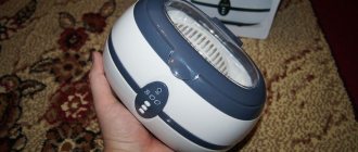
An ultrasonic bath is a special equipment that cleans and disinfects various objects using ultrasound.
Items that need to be cleaned are placed in a special bathtub reservoir filled with a cleaning solution. After this, they are treated with ultrasound. Under their influence, physical effects occur such as: - Cavitation effect. Over a short period of time, under the influence of ultrasound, many air bubbles are formed and destroyed in the solution. — Acoustic flow. Ultrasonic waves passing through obstacles create a vortex flow. — Increase in pressure due to the elasticity of the medium. — Sound-capillary effect due to which all voids in the medium are filled with the working solution.
All these effects together lead to the destruction of the bonds between the surface of the object and the contaminants located on it. After which the latter are easily removed.
Ultrasonic bath. Part 1
Hamsters welcome you, friends. Today's post will be devoted to the creation of an ultrasonic cleaning bath based on a piezoceramic Langevin emitter with a power of 60 W. In the process, we will look at what the device consists of, how to set it up so that nothing burns, and in the end we will see cleaning abilities that are superior in their effect to Mr. Proper and all his friends. An ultrasonic bath has many applications and it is almost impossible to list them all, since most of them will depend only on your imagination.
Before we start dissolving our fingers in an ultrasonic bath, let's look at how mechanical vibrations arise in simpler systems. One example of such oscillatory mechanisms is magnetostrictors, which can be compressed or stretched under the influence of a magnetic field. An ordinary ferrite from an old grandfather’s radio, which everyone probably has lying around somewhere in their garage, has these parameters.
To start the experiment we will need:
signal generator, pulse density modulator for power control, half bridge, adjustable power supply and oscilloscope for visual signal evaluation. Next, we wind a coil of thick copper on a small mandrel; in my case, it turned out to be about 50 turns of 2 mm wire. The ferrite will be inserted right into the middle of this gauss gun. We set the power on the pulse modulator to 100 percent. By rotating the knob on the generator we find the resonance of the system, which in a particular case will look like two mountains, the tops of which need to be leveled.
The frequency of a particular rod turned out to be 8.5 kHz.
Approaching mechanical resonance, you can see how the drop on the top of the ferrite rod begins to vibrate, changing its original shape. At some point, the vibration amplitude reaches such a magnitude that the water breaks into thousands of small particles and visually it seems that the liquid turns into fog in a split second. The size of each such drop depends on the mechanical system; the higher the frequency, the smaller the drop.
Such a magnetostrictive system is bad because at a certain power threshold, brittle ferrite breaks into pieces, as happened now.
15 W turned out to be unacceptable. In the middle of the rod, maximum mechanical stress arises, so it breaks. If you then try to glue the two halves of the rod together, then there will be no such active work as it was initially, since each individual piece will have its own mechanical resonance. During filming, three of these rods broke.
As an experiment, let’s connect the most common piezoceramic emitter to the generator.
By rotating the generator handle, we find the moment when the water begins to be actively disturbed. As you can see, the droplets that formed are slightly larger in size than in the previously presented version, since the resonant frequency here is 2 times lower and corresponds to 3.6 kHz.
For reference.
Ultrasonic evaporators and air humidifiers use the same principle, only the frequency here is already in the megahertz range. The size of a water drop can reach several tens of microns.
Now we turn exclusively to the Langevin emitter, named after the French physicist who worked on magnetism. The electromechanical frequency of this piece of iron is 40 kHz, and the evaporation of water on it is more like the eruption of some kind of volcano. At such idle speed the emitter gets very hot, so I don’t recommend doing this.
In the next experiment we will try to obtain ultrasonic levitation.
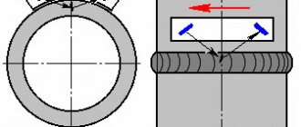
At resonance in Langevin, a standing ultrasonic wave is formed with an antinode at the end of the radiating pad. This is the main longitudinal mode. In this case, the particles of the substance at the end of the pad oscillate in the vertical direction with an amplitude of tens of microns. These vibrations are easily transmitted into the air.
If a reflective surface is installed at a certain distance from the emitter, then the emitted and reflected waves will add up, forming standing sound waves in the air that have nodes - areas of minimum pressure, and antinodes - areas of maximum pressure. In order for the foam ball to levitate, it must be placed precisely in the sound pressure unit. If you turn off the system, the whole house of cards will immediately collapse.
We figured out the principle of Langevin’s work.
Now you can take a closer look at the emitter. On the front side you can see the sandblasted matte surface, which provides better adhesion to the glue that will fasten the emitter to the gastronorm container.
The volume of such a trough is one and a half liters.
Vessel size 1/6, depth 100 mm, material stainless steel. We center the emitter at the bottom of the vessel and mark the place where it will be located. Essentially, this is necessary to ensure that sandpaper marks do not go beyond the borders and spoil the appearance. Ideally, it would be better to sandblast this area, but I don’t have that on my farm. When the surfaces are prepared, degrease them with acetone and dilute epoxy glue.
We apply it in a thin layer to the trough itself and carry out the same procedure with the emitter. There should be no gaps, since we need to ensure good acoustic contact of the entire radiating surface. When the shuttle docks, Langevin tries to crawl away somewhere. To prevent it from running far, you need to rub it in a little, and then press down so that all the excess glue crawls out.
After polymerization, the epoxide will acquire the so-called metallic hardness.
For amateurs, this option to start working with powerful ultrasound can be quite rewarding.
Now it's time to make the body.
We mark pre-measured dimensions on 10 mm chipboard and begin work with a jigsaw. It is advisable to do this operation at night, when all the neighbors are sleeping)
The end result will be 5 even pieces; all you need to do is fasten the plywood walls more securely so that nothing falls apart. We try on the bathtub by inserting one into the other. Ideally, the box should be slightly smaller than the size of the gastronorm container itself.
Let's move on to the electronic part.
To control the operating time of the bath, you need a timer. I found a suitable circuit on the Internet, but I had to wire the printed circuit board myself since it was simply not in the description. The result was a small scarf with fairly modest dimensions. Exactly what is needed.
We supply power and see how something lights up.
Briefly pressing the encoder button turns the timer on and off. Turning the knob allows you to select the time in minutes from 1 to 99. After the specified interval has expired, music plays, and then a siren sounds, which can be turned off by pressing the encoder once. The job couldn't be easier. If someone is bothered by sound signals, there is a jumper on the board that turns off the speaker.
Now it's up to the generator, which will pump the speaker system.
I tailored the board exclusively to the dimensions of the parts that I dug up in the pantry. I tried to place the elements as closely as possible so that there would be no high-frequency interference. Although the option assembled from shit and sticks on the knee also worked well, it’s not worth doing.
The generator is called push-pull.
At the beginning it had IRFZ46 transistors, then 2SK1276, then IRFP460, all of them seemed to work somewhat sadly. The IRFZ44 transistors worked best, so I settled on them. Control comes from the IR2153 driver chip.
Since the frequency control will be manual, in some modes the transistors will get very hot.
Therefore, it is necessary to provide for good heat dissipation. It is advisable to use a radiator with a thick base, since its heat removal will be much more efficient than that of the piece of aluminum located on the left, which overheats like a first-grader on a first date. In any case, it is necessary to ensure good heat removal and air cooling. The temperature value will be displayed on a Chinese thermometer with an LCD screen. This one costs about 2 bucks.
All the energy in the bath will be pumped by a pulse transformer from the computer power supply.
From practice, the size of the transformer does not matter; everything worked the same on both small and large such crap. 60 W is like two fingers for them. We will estimate the consumption of the entire circuit using the ammeter readings of a powerful shunt connected in parallel. For our task we need a strong power supply. This board was taken out of a charger from some laptop. According to the specifications, it produces 65 W at a voltage of 20 volts. Dividing the first by the second we get a current of three and a quarter amperes, which is very pleasing.
Now this pile of spare parts needs to be placed in a checkerboard pattern.
To do this, we use all our artist skills on wooden boards and mark the pre-planned places where the controls will be inserted. The clean work is completed, it’s time to cover the carpet with chipboard sawdust, which falls like snow while drilling holes. We remove rough marks from the drill with a drill. Since the nozzle is round, all that remains is to trim the corners and then the file comes into play. But you need to work with it carefully, as the decorative coating may chip. Once the dust has settled throughout the house, decorative woodworking can be considered complete.
We place all the electronics.
It's good form when all the parts fit tightly. We place the timer board on the back side, and on the front side there is a Chinese thermometer that shows the temperature in tenths of a degree, and we also install the remaining breakers and switches. The result will be something like this.
We place the power supply inside, as you can see it is located near the blowout hole for better cooling. We place the generator board opposite the fan and place the last element - the inductor.
How does this whole pile of iron work?!
Let's figure it out now. To start setting up, set the voltage on the regulated power supply to about 14 volts. We check the stabilized voltage for powering the driver chip, it should be 12 volts. Using an oscilloscope probe, we cling to the gate of the transistor and check whether the signal is present in the form of a meander. If everything is in place, use a variable resistor to change the frequency and make sure that the signal does not twitch and is smooth throughout the entire adjustment range. In this case, the upper limit is about 80 kHz, and the lower limit is around 34 kHz. The supply is large enough and, as they say, does not pinch the pocket.
We turn on the divider by 10 on the probe and connect to the middle leg of the field operator - this is the drain.
At idle, you can see how, at the moment the transistor is turned on, a high-voltage surge occurs, followed by a free damped oscillation compared to hitting water. At the moment the key is turned off, we see another peak. Ideally, this place should have a clean meander. But it looks like he's gone crazy. Let's try to connect a load in the form of an Ilyich lamp. We see how the attenuation has disappeared, the leading edge of the meander is in the blockage, and inductive emissions reach about 700 volts. This picture is no good.
Part of this horror occurs in the board; even your finger affects it.
The same signal will be repeated at the output of the transformer. You can see how a dead time of 1.2 milliseconds is formed between the activations of each arm. Absolutely, except for the signal shape, the work is going in the right direction.
High-frequency ringing can be suppressed with a snubber.
This is the name of a chain of a resistor and a capacitor. In this case, the resistor must be powerful, about 5 W, since it gets very hot. Let's place them in the radiator blowing area. By connecting the RC chain to one of the arms of the push-pool, you can see how the waves are damped, albeit with a slight disturbance at the moment of switching on. This is the best I could achieve by experimentally selecting the capacitance and resistance of the snubber for this circuit. In any case, even under load, the signal at the output of the high-voltage part of the transformer tends to resemble a meander. We've sorted this out, let's move on.
Since the emitter is a capacitive load, it is necessary to calculate a resonant choke for it, which will increase the operating efficiency.
We measure the capacitance and get approximately 5 nF. The frequency of this Langevin is 40 kHz. We go into the “Electrodroid” program and enter these parameters there. An ingenious program for poor students, you don’t need to count anything, just enter numbers, the program will do everything for you. According to the calculation results, the inductance came out to be 3.2 mH. We will wind the transformer with double wire to reduce the total resistance. Less resistance, less losses that will be dissipated in the form of heat.
The first version of the inductor was wound on the core of an unassembled transformer. This took about 4 hours, since it was difficult to lay copper coil to coil. The final inductance with all efforts came out to 0.6 mH. I was upset. You can wind the sample into one wire on an ordinary piece of ferrite; there will be a lot of losses, but this option will work for tuning.
So what do we see here?!
There is a current transformer at one end of the emitter; in the future it will be of little use. At the hot end of the inductor we hook up a neon light bulb to visually assess the voltage. Pour some water into the gastronorm container, about 1/3 full. We connect the oscilloscope probe to the high-voltage output of the transformer.
We raise the tension and see...
Fuck it! At resonance, at maximum consumption, the meander sinks as much as you want, forming two peaks like in the film The Lord of the Rings. I suspect this is the effect of the choke on the power supply to the low-voltage part. The voltage range is apparently considerable, so I don’t recommend doing it this way. We connect the probe with a divider to the hot end, adjust the frequency and see how the voltage amplitude swings beyond the measurement limits of the oscilloscope. The swing is approximately 1000 volts. The second end of the neon lamp gets pinched if you touch it.
Let's see what's on the current transformer.
The picture jumps due to poor synchronization of the oscilloscope. Anu synchronize old junk. Don't take me out! The current at resonance increases as it should. If the water in the bath dangles, then the operation of the system becomes unstable.
An interesting effect discovered during experiments.
If one end of the Langevin is not connected to the common wire of the circuit, then the entire voltage potential in kilovolts appears on the bath body, this is clearly visible on the neon light bulb. There are even small sparks when touching a piece of iron. The board is pre-provided with a Langevin grounding jumper.
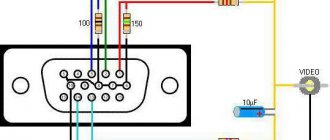
Electronic part diagram.
I tried to indicate everything in it, even the pinout of the transistor. There is a contactor on the choke of the resonant part. I noticed that sometimes the bath works better without it than with it, and sometimes vice versa.
For clarity, two pictures with signals are shown below.
The first one works with a capacitive load, and the second one with a resonant one. Archive with all the necessary materials for assembling a bathtub.
We sorted out this part, it looks like nothing burned, we move on.
We connect all connectors with power supply, control, variable resistors, keller, etc. Since the thermometer temperature sensor has a very convenient shape for mounting, I couldn’t think of anything else other than attaching it to a piece of foil tape, although it would be more correct to drill a hole in the radiator and stick it there along with thermal paste for better thermal contact.
The body of the bathtub is made of chipboard, and as you know, it is afraid of water, or rather its unprotected sides. Waterproof silicone copes well with such tasks. We separate a piece of this muck and rub it into the ends of the wood. It’s important not to rush anywhere, we’re doing it for ourselves. Also, the damper tape will be better adhered to the silicone, which will isolate the body of the gastronorm container from the body of the device so that beneficial vibrations are not damped.
To attach Langevin to a stainless steel trough, instead of epoxy resin, you can use cold welding of the “Poxipol” type. It seems like bathtub manufacturers use it. Let them use it, regular epoxy is several times cheaper.
For reference.
You should not leave things unattended, otherwise hamsters will come running and chew all the wires. But don’t be afraid if you have a soldering iron nearby, you can always fight back) To say that the bathtub turned out to be compact is an understatement compared to the Chinese ones, but how much power is there...
Second part
Archive with useful things Full video of the project on YouTube Our Instagram
Solutions used
The cleansing properties of ultrasonic waves are only possible in a liquid medium. Therefore, there are special requirements for solutions for ultrasonic baths. They must have good solubility and fluidity. They must conduct ultrasound well. And not have a negative impact on the surface of the equipment and items being cleaned.
When cleaning, you should also take into account that its quality depends on factors such as: - composition of the solution; - his temperature; - freshness of preparation; - a sufficient amount of solution necessary to completely immerse the items being cleaned in it.
Rating
BAKU BK-3A (0.50L/30W) BK-3A
pros
- compact and fast operation
- Cleans well, consumes little electricity
Minuses
- not found
From 1088 ₽
Donfeel HB-382
pros
- excellent quality-cost ratio
- used for cleaning parts of complex configurations
Minuses
- The security system turns off the device during prolonged operation
From 3400 ₽
SD – 3000
pros
- unique compactness and low weight
- Great for cleaning small items
Minuses
- not found
From 5360 ₽
CODYSON CD-7810A
pros
- Cleans any jewelry in 10 minutes
- Has a CD holder
Minuses
- not found
From 3000 ₽
Skymen JP-3800S (0.6L/35W) JP-3800S
pros
- modern design
- several time modes
- function of degassing from solution deposits
Minuses
- not found
From 2200 ₽
What to look for when choosing
When choosing this equipment, first of all you need to focus on the size of the objects that will be constantly cleaned in it. The volume of the tank of the purchased bath depends on this. It is desirable that the model has the ability to adjust the length and frequency of ultrasonic waves. And a timer for setting the time required for work.
The trays and grids used in the work must be made of plastic. Since metal reflects waves, which can interfere with the work process.
If disinfectant solutions will be used, then you need to choose a model without a heating module.
Considering that there is a wide range of ultrasonic baths on the market, you can always choose the ideal option based on your needs.
In our online store you can purchase a wide range of ultrasonic baths at low prices. Contact us!