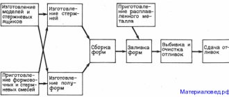
According to gasified models
The mold is obtained using a non-removable model, and the metal is poured into a permanent mold. In this case, the model is produced from foam plastic by foaming at high temperature. When metal is cast into a mold, the foam model burns out completely, freeing up the internal volume.
If models for small parts can be obtained by foaming the composition, then large ones are cut out from glued slabs. Cutting is done by hand. Nichrome wire is used for this. The applied voltage heats the wire, which makes cutting easier.
The model can also be cut on milling or engraving machines with numerical control according to a given algorithm. The prepared model is painted and additionally coated with a heat-resistant compound.
Forming during lgm is carried out using two methods. In the first case, for castings of simple shapes, vibrating tables are used, on which the molding sand is compacted using flasks. Then the lid is placed on the flask and the sprue receiver is mounted.
In the second case, when the product has a complex geometry, molding is carried out under vacuum. To prevent the closed mold from collapsing, it is subjected to reduced pressure until the end of pouring. The vacuum pressure value is low - about 4-5 GPa.
Blanks for casting using gasified models
The temperature of the poured metal is significantly higher than the beginning of foam gasification (560 °C). The gases released by the foam are easily removed from the mold by a vacuum system. At the same time, there is no smoke in the working area.
The main advantage of this method is the high quality of castings, which can be obtained by casting into an ordinary or lined chill mold. This became possible due to the fact that the shape is solid.
Casting using gasified models
At the present stage, casting using burnout models is used for casting:
- large and medium-sized products in small-scale production;
- workpieces with complex configurations and weighing up to 50 kg, which are subject to increased dimensional accuracy requirements, in medium- and large-scale production.
Metal casting
Metal casting is a production process based on the technology of pouring molten, hot metal into special molds, as a result of which cast blanks are obtained - castings. The cavity of the molds repeats the configuration of future workpieces and represents the working part of the casting mold, where the liquid metal enters. Here, future workpieces are cooled, hardened and given the appearance of the final product. Before delivery to the consumer, aluminum castings undergo mechanical processing (turning, milling, grinding and polishing).
This method is used to produce aluminum castings, which, due to their unique chemical properties, are used in many fields: in instrument making, construction, automotive, furniture production (fittings and decorative parts), etc. To obtain them, various technologies are used, the choice of which depends on sizes, configuration and other indicators required from the final product.
Under pressure
Injection molding technology involves the rapid supply of melt into a mold using compressor or piston mechanisms. Thanks to the automation of the process, injection molding is considered high-productivity.
In this way you can get details:
- complex geometric shape;
- with fairly thin walls;
- high precision;
- with increased roughness.
The injection molding method is used to produce parts in the automotive industry. They are light in weight and have sufficient strength, which helps reduce the total weight of the unit.
It is worth noting that the high pressure casting method has the following advantages:
- possibility of obtaining sizes of class 9 and coarser;
- achieved surface roughness - 1.25 microns;
- minimum wall size - 0.6 mm;
- minimum hole diameter - 1 mm;
- external thread formation;
- knurling, inscriptions on the outside.
The disadvantages include the following:
- the price of the forms themselves is high;
- spill of metals with low melting point;
- increased likelihood of the formation of internal defects in the form of cracks and stresses.
Die casting diagram
The widespread use of aluminum die casting is due to:
- low temperature values during the crystallization period;
- plasticity of the alloy;
- good fluidity;
- inertness to chemical reactions;
- low volume of shrinkage.
Considering ways to divide technology as follows:
- pressing chamber: hot;
- cold;
- horizontal;
- piston;
Process flow
The melt is fed into a special cavity. The piston pin forces liquid metal at high speed into the internal cavity of the mold. After which cooling occurs without removing the pressure. After hardening, the mold is released and the casting is removed. To facilitate extraction, the structure is equipped with pushers.
Application of shell forms
Molten metal is freely poured into shell molds based on thermosetting mixtures.
A type of casting method with one-time sand molds. The result is surfaces with high quality workmanship. The mixture is based on quartz sand and resin of synthetic origin. At 70 degrees, phenol-formaldehyde resins begin to dissolve, their melting point reaches 120 degrees. After a few seconds, the material begins to harden. At 450 degrees, the resin burns out. Methods for obtaining shell forms are based on the ability of resins to pass from a liquid to a solid state irreversibly. After pouring, the model is easily destroyed, freeing up the necessary space.
In the chill mold
When casting into a chill mold, or into metal molds, liquid metal is poured freely, that is, under the influence of gravitational forces. The mold itself is made of two collapsible parts mounted on a plate. To obtain cavities and holes into the provided grooves into which the rods are placed. Steel and cast iron are used to make metal molds.
Chill casting process
Ventilation ducts are provided to remove gases during pouring. To prevent the melt from sticking to the internal surfaces of the chill mold, they are lined or painted with fire-resistant compounds. The thickness of the coating depends on the metal being poured and its cooling rate. Before coating, the mold cavity is cleaned and then heated to temperatures of 150 °C - 280 °C.
Features of obtaining castings:
- Due to their high thermal conductivity, alloys cool quickly in the mold, so alloys with low fluidity should have maximum wall thickness. The high cooling rate forms a fine-grained internal structure.
- The metal mold is non-yielding, so the casting is free from defects caused by permanent deformation and also prevents shrinkage. The resulting accuracy of workpieces: steels and cast irons – 7-11 classes, non-ferrous alloys – 5-9 classes.
- No burning.
- The achieved surface roughness corresponds to Rz = 40-10 µm.
- The chill mold is a gas-tight structure. Ventilation ducts and fire-resistant coatings cannot completely remove gases. In this regard, gas sinks are a common occurrence.
Advantages of chill casting:
- constant characteristics for the resulting castings;
- possibility of using sand cores;
- high performance;
- small number of operations performed;
- clean surface of finished products;
- mechanization of work;
- low qualification of workers.
Negative sides:
- significant cost of forming equipment;
- limited durability of forms;
- rapid cooling of the melt.
Almost all metals are cast into the chill mold, but the majority of castings are cast iron and cast steel.
Purpose of cast concrete, its advantages and disadvantages
Using poured concrete as a self-leveling mixture
Cast concrete is a building material classified as hydraulic. Its main difference from the usual one is the use of fine sand as a filler and the use of plasticizers, which gives the mixtures excellent fluidity and elasticity.
- The main binder is cement. Various plasticizers and modifiers are used as additives, thanks to which the finished concrete has low shrinkage, easily spreads over the surface and does not delaminate.
- Additives also allow moisture to remain in the composition longer, so surface adjustments can be completed over a longer period of time.
- On many resources you can see information that cast concrete does not need vibration compaction. This may be partly true, but not entirely. The fact is that air bubbles intensively form inside the mixture when mixing it, so vibration when making shapes of varying complexity, or rolling with a needle roller in the case of a self-leveling floor, is simply necessary.
- The final surface of cast concrete tolerates moisture much better (it penetrates its structure less well), thanks to which the material tolerates temperature changes well.
- Cast concrete is used not only for the manufacture of finishing floor coverings. This material is very popular among designers of all stripes for creating decorative figures of various sizes and complexity. Here is a small photo gallery showing such creations.
into the ground
Casting into the ground or into molds from a mixture of sand and clay is the oldest method of producing molten metal blanks. Over 80% of all castings come from it. It is distinguished by the simplicity and availability of the materials used.
The model and sprue kits are made from wood. After the model is ready, the molding mixture is mixed. The simplest ones include sand, quartz and clay.
Earth casting technology
Forming is done both manually and by machine. Manual mold making is used for the production of single or multiple castings and is considered unproductive. Machine forming is used on automated casting lines. Casting molds consist of two halves and are disposable. After pouring and cooling, the molds are destroyed. More than half of the waste material is returned to the molding operation after purification and recovery.
Hello student
Obtaining cavities in the molding material that correspond to all the outlines of the object being cast, for subsequent filling with molten metal, is achieved by imprinting a model of the object in the molding material. The molding material with the voids imprinted into it using a model forms a casting mold.
To obtain voids or depressions in the cast product, rods are inserted into the casting molds.
By an appropriate combination of shapes and cores, all possible shapes of cast objects can be obtained.
The model is not an exact copy of the object being cast on it and is often made detachable for ease of molding.
Such a deviation from the exact outlines of the object being manufactured according to the model is caused by the need to strengthen the core marks in the molding material, the need to form holes in the cast object, shrinkage of the metal during casting, allowances for material for processing the casting and the need to form so-called profits - massive appendages to the mold intended for feeding the latter with metal as it shrinks. The model is made detachable in order to facilitate the removal of the model from the mold and to facilitate molding work.
In fig. 190 shows a diagram of the molding of the sleeve.
Casting molds are called open if the molten metal is covered only from below and from the sides; if the mold encloses the metal on all sides, it is called closed.
Models.
The most commonly used material for making models is wood; it is relatively cheap, lightweight, and easy to process. Metals are less commonly used: cast iron, bronze, brass, aluminum alloys. Metal models are more expensive, but last much longer. They are usually used when casting a large number of homogeneous parts; then the cost of making the model is divided into a large number of castings, as a result of which the rise in cost of the latter is insignificant.
The wood used to make the model must be dried very thoroughly, otherwise the models will warp and crack. Since when drying wood contracts differently in different
directions, the models are usually glued together from separate pieces with an arrangement of fibers that ensures minimal deformation during shrinkage.
To eliminate swelling of the wood when it comes into contact with wet molding material, the models are painted with alcohol varnish.
Models for cast iron castings are painted red, for steel castings - blue, for bronze and brass - yellow; signs are painted black; Models are marked before delivery to the warehouse.
In fig. 191 shows a model of a pulley rim glued together from separate pieces.
In fig. 192 shows a model of a pipe with two pipes, which separates along planes A B and CD; in the planes of contact of the parts of the split model, holes are made in one part, and tenons are made in the other, which, entering the corresponding holes, properly position one part of the model relative to the other.
To ensure proper dimensions of the cast item, taking into account shrinkage
metal in the production of models, a so-called shrinkage meter is used. The shrinkage meter must provide a correction for the shrinkage of the casting, depending on a particular metal. So, for cast iron castings the shrinkage meter is not 1000, but 1010 mm with the number of divisions equal to 1000, for aluminum castings 1014, etc.
The use of a shrinkage meter eliminates the need to calculate each time the increase in shrinkage to the dimensions indicated on the drawing.
Manufacturing of rods.
The rods are manufactured in core boxes. Large size rods are made using templates.
The rods are a very important part of the form; Their role is especially important when casting products with large internal cavities.
Since during casting the rod is washed with molten metal, the material for making the rods must have maximum fire resistance and gas permeability. At the same time, this material should not offer much resistance to metal shrinkage and should be easily knocked out after casting.
In fig. 193 shows a core box, which consists of two halves connected by tenons. The cavity formed by folding the halves (with the box in a vertical position) is filled with earth. To form a ventilation channel, the rod is pierced with wire; the ventilation duct must be located exactly in the middle of the rod.
If it is necessary to place a long rod in a mold in a horizontal position,
To increase strength, a metal frame is installed. To form ventilation channels, waxed wicks are laid in curved rods; When the rod is dried, the wax melts, after which the wick is removed, in its place a channel remains.
In fig. Fig. 194 shows the sequence of operations for manufacturing the core: a through board is placed on the lower half of the core box, through the cutout of the through board, both the lower half of the box and the cutout of the through board are filled with molding soil (Fig. 194, a); the through board is removed (Fig. 194, b); the upper half of the box is applied (Fig. 194, c); the top half of the drawer is removed. In fig. 194, d you can see the resulting rounding of the trapezoidal outlines of the rod. The area of the trapezoids here is equal to the area of the semicircles with some excess, to accommodate which narrow grooves are made along the parting line of the box. The prepared rod is dried, after which the burrs formed in the parting plane are carefully removed from it with a rasp.
It is advisable to divide rods of complex shape and large size into several parts rather than mold them at once.
The work expended in joining the parts of the rod is repaid by the savings in the manufacture of the rod in parts and the possibility of using cheaper molding material, as well as the convenience of drying.
Molding.
Molding is a set of works for the production of casting molds from molding materials that can withstand the impact of molten metal and give it their shape.
Molding can be classified according to various criteria: 1) according to the type of devices with which the shape is obtained, molding is divided into pattern molding and template molding; 2) in the place where the molding material is located - on the ground and in flasks (boxes are called boxes in which the molding material is placed, forming a casting mold); 3) by the type of molding materials - for molding in lean soil, molding in fatty soil and molding in clay.
Depending on the degree of mechanization, molding work is also divided into manual and machine.
In practice, various types of moldings are combined, for example, model with template, soil with flask.
The choice of one or another method of making a mold to obtain a high-quality casting of the required shape is ultimately determined by the cost of the work. Due to the fact that making models is generally very expensive and sometimes exceeds the cost of the casting itself, the use of model molding is beneficial only when a large number of castings will be produced from the model. Making casting molds using templates is cheaper, but requires more highly skilled workers to complete it.
Regardless of economic considerations, pattern molding can produce shapes of all possible shapes, whereas template molding has a limited variety of shapes. Therefore, in most cases, model molding is also used in the manufacture of only one object by casting.
Forms that are large in length and width with a small height (beds, slabs) can be prepared “raw” (in wet sand); for objects of significant height that are cast vertically (pipes, cylinders), molds are prepared “dry”.
When molding in soil, forms can be open or closed; Objects that are not subject to processing are usually cast in open molds, for example, grate bars, anchor and building slabs.
Machine molding is used in mass and large-scale production. Machine molding has a number of advantages over manual molding; it allows you to: 1) mechanize the processes of compacting the molding material and removing the model from the flask; 2) obtain forms with uniform compaction; 3) obtain castings of more accurate dimensions; 4) make better use of the labor of molders, freeing them from installing and removing models, correcting shapes, etc.; In addition, machine molding produces less waste compared to manual molding.
The question of the economic profitability of using machine molding can be resolved by considering the following inequality:
where N is the number of flasks molded per year;
M is the productivity of the molding machine per day per worker, expressed in the number of molded flasks;
t is the average daily cost of a molder’s work during machine molding;
A is the annual amount of depreciation costs attributable to the molding machine and auxiliary equipment;
B is the annual operating costs associated with the operation of the molding machine;
C is the amount of depreciation costs for equipment for manual molding;
D is the annual operating costs associated with hand molding (excluding labor);
R is the daily output of one worker when working manually, expressed in the number of flasks;
r is the average daily cost of a molder's manual labor.
Obviously, the smaller the left side of the inequality is compared to the right, the more economically profitable it is to use machine molding.
Forming tool.
The tools used in molding work are mainly used for digging, mixing, laying, sifting, leveling and compacting molding soil, as well as for correcting casting molds. For molding work, shovels, sieves, rammers (manual, pneumatic and electric), smoothers, knives, hammers, hooks, spoons, rulers, brushes, bellows, dust bags, light bulbs with reflectors, ink brushes, spray guns, levels, plumb lines are used. . In fig. 195 shows various hand rammers; in fig. 196 shows a pneumatic rammer, FIG. 197 shows irons of various shapes.
Opoki.
Opokami are boxes (without a bottom or a lid) into which molding material intended for the manufacture of foundry molds is stuffed.
Forms enclosed in flasks better resist the pressure of molten metal. Molding in flasks, due to the ability to place the mold in any position, offers a number of conveniences; in addition, when making molds in flasks, molding can be done in one place and casting in another, transferring the molds to the casting site.
Thus, the use of flasks provides a number of advantages, but requires the expenditure of funds for the manufacture of flasks, which are usually made of wood or metal. Wooden flasks are cheaper, but wear out faster - they burn out, are destroyed under metal pressure, and are damaged when moved by a crane. It is advisable to use wooden flasks only when casting one object, the dimensions of which do not fit the dimensions of the metal flasks available to the foundry.
The size of the flask should not significantly exceed the size of the model, since otherwise it would be necessary to waste a large amount of molding material and unproductively expend labor on stuffing; It is considered sufficient to leave a distance of about 20 mm between the walls of the flask and the model.
The shape of the flask is determined by the shape of the model - it can be rectangular, square, polygonal, round and shaped.
The number of flasks used to make one mold is determined by the minimum number of parts into which the model must be divided in order to remove it without damaging the mold.
If the mold is made in several flasks, then the latter must have ears and clamps, through which the flasks are installed in a certain position relative to each other. For ease of movement, handles are attached to the flasks. The sides inside the flask are intended to support the molding material.
In fig. 198 shows two wooden flasks for flaskless molding. These flasks can be opened to remove them from the finished mold. In this case, casting is made into a mold that is not supported by a flask; to avoid breaking through the flaskless mold with liquid metal, a frame of strip iron 60-70 mm high is inserted into each flask before molding; In order for the frames to easily fit into the flasks, their dimensions should be 4-5 mm smaller than the internal dimensions of the flasks. After removing the split flask, the frames remain on the mold.
In fig. 199 shows flasks for flaskless molding of a different design - removable flasks. To avoid the breakthrough of liquid metal, wide conical frames made of sheet iron, called jackets, are put on conical flaskless forms made in such flasks.
In fig. 200 shows cast steel flasks with holes in the walls (for the release of gases from the mold).
Forming methods
Soil molding is the cheapest, most inconvenient, and least clean forming method. The cheapness is due to the absence of expenses for the manufacture of flasks, the inconvenience lies in the need to deal with a completely motionless mold, and the lack of cleanliness is explained by the constant digging of the foundry floor.
Ground molding can be open, when the cast object is limited by a horizontal plane formed by the molten metal, and closed, when the mold is limited from above by one flask.
The first method is used in cases where the plane formed by the free surface of the molten metal may not be particularly clean.
The work begins with preparing the bed for the form. To do this, the model is placed on the ground, and its projection is roughly outlined, after which a hole is dug of such dimensions that its edges extend beyond the projection of the model by at least 20 cm, and its depth exceeds the height of the model by approximately the height of a shovel. An even layer of coke is placed in the prepared hole, and on top of the coke is the soil obtained when digging the hole, which is usually old molding material.
A coke bed is arranged to better remove gases released during casting from the mold. For castings of small thickness (slabs), the coke bed may not be used.
In fig. 201 shows an open mold for casting a slab, prepared in soil. To fill mold 1, there is a recess - funnel 2, into which molten metal is poured, filling the mold through channel 3.
Usually, when casting into open molds, the depth of the latter is made somewhat greater than the thickness of the product being cast, and at a level corresponding to this thickness, a channel is cut in the molding material through which excess metal is removed from the mold; With this device, the danger of overfilling the mold is eliminated and castings of the required thickness are achieved.
When casting into open molds, due to the small hydrostatic pressure developed in this case by the metal, the corners of the casting are always slightly rounded.
When casting an object in the soil, the upper part of which must have complex outlines, it is necessary to use flasks to obtain the required surface of the mold. Such an intermediate molding is shown in FIG. 202; Here is a mold for casting a bearing cap. Making the mold in this case consists of six operations:
I) prepare the soil; 2) the model is molded in the soil to a level that ensures removal of the model without damaging the mold; 3) when the model is molded, the surface of the molding soil is sprinkled with dry, clean sand.
serving to protect the molding material located in the soil from sticking to the material filling the flask; 4) the flask is installed; Several pegs are driven around it so that later the flask can be placed exactly in its original place, and two conical risers are also installed - one to form sprue 2, the other to form hole 1 for air and gases to exit the mold (outflow); then the flask is filled with facing material and finally molded with filling earth; 5) when the flask is filled, the ground in it is compacted and leveled, the flask is raised, the model and conical risers are removed and rods 3 and 4 are installed; 6) seasoning and dusting the mold and installing the flask in the old place.
Molding in flasks.
The models from which casting molds are made, in most cases, have outlines that do not allow the model to be removed from the molding material without damaging the resulting mold; Therefore, models are usually made detachable, and two or more flasks are used for molding them. The most widely used method is flask molding in two flasks using a model board.
A board that is planed on one side and has two dowels on the other is called a model board. During molding, this board is placed under the model and the flask, inside which the model is molded. The size of the fake board in length and width should be 2-3 cm larger than the largest of the flasks served by this board. If a model board has through holes all over its surface, then it is called a pallet. A tray and a model board are necessary accessories for molding in two flasks.
The molding process is as follows.
1. The fake board is placed on a workbench or on the floor and half of the model is placed on it so that the parting plane is adjacent to the board.
2. Place the flask on the model board with the ears downwards so that the part of the model standing on the board is inside the flask.
3. The model is filled with fresh molding soil through a sieve; The molder presses this facing soil onto the model by hand and then covers it to the edges of the flask with sifted old molding material (filling soil). All molding material filling the flask is compacted.
4. The flask filled with compacted material is covered with a pallet, rotated together with the under-model board and pallet by 180°, placed on a workbench or table, the under-model board is removed and the surface of the molding material is sprinkled with dry sand or coal powder to protect the molding material of the lower flask from sticking to the molding material. material of the upper flask.
5. Blow off the sand from the model with fur and place the second half of the model on the first half and the second flask on the first flask, cover the second half of the model and the molding material of the first flask with a layer of fresh molding earth, press it manually onto the model, fill the second flask to the top with old earth and compact it land; In addition, when filling the upper flask with earth, care must be taken to install the sprue model and the stop in the flask.
6. Remove the sprue model from the upper flask, expand the upper part of the sprue, giving it the appearance of a funnel, and cover the upper flask with a fake board.
7. Separate the flasks, and with them separate the halves of the model; The upper flask is turned over with the model up and the halves of the model are pulled out from both flasks.
8. Correct the molds (in case of damage when removing the model), dust their surface, insert cores if they are required by the design of the part being cast, fold both halves of the mold and fasten the flasks. After this, the mold is completely ready for casting.
The molding process in two flasks is shown in Fig. 203. The sequence of operations is indicated by numbers.
All the described molding techniques in two flasks are repeated when molding in a larger number of flasks. When all the flasks are molded, they are removed one by one, parts of the model are removed from them, the molds are corrected, dusted or painted and then reconnected in the same order.
Example. In fig. 204 shows the model and shape of the ball branch. The molding method is similar to the case of molding in two flasks described above. First, fill the middle flask with part of model 2, then the bottom with flange 3 and, finally, the top with part of model 1.
Template molding.
Template molding is used mainly in the production of casting bodies of rotation, for example, flywheels, pulleys, and boilers.
Necessary devices for template molding: a stand, a sleeve, one end connected to a sleeve put on the stand, and the other to a template, and the templates themselves. In fig. 205 shows a machine for template molding of bodies of revolution.
In fig. 206 shows the molding of the runner bowl. Sketches b, c, d and e show in sequential order the manufacturing operations using casting mold templates for this part.
The work consists of the following operations.
1. The soil is loosened in an area the size of which corresponds to the size of the mold being made; the loosened soil is compacted tightly.
2. Install template 1 (Fig. 206, b), corresponding to the outer contour of the mold being manufactured, and, immersing it to a small depth in the molding material, slowly turn it around the stand in a full circle;
when a certain layer of material has been removed in this way, the template is deposited and the next layer is removed; work continues until a hole is formed in the soil, the profile of which matches the outline of the template.
3. Remove template 1, place flask 2 around the pit (Fig. 206, c) and mark
its position with pegs driven in near the walls; sprinkle the hole with separating material (dry sand, crushed coal) and fill the flask, after
whereupon the latter is turned over and, if necessary, adjusted to the shape of the outer surface of the part being manufactured.
4. Destroy the shape cut out with a template in the hole, loosen the soil in the hole, add fresh soil and compact it; a template 3 is installed (Fig. 206, d), corresponding to the internal contours of the object being cast, and by rotating it, a shape corresponding to the template is obtained in the pit.
5. The template is removed, the mold is adjusted, the flask is placed, and the result is the casting mold shown in FIG. 206, no.
Molding using model plates.
When molding a significant number of homogeneous small-sized castings, model plates are used, which are usually split models of several objects connected to each other by a common sprue. In modern foundries, large castings are sometimes formed using pattern plates. Molding according to
model plates offer a number of conveniences: the models are permanently positioned in the flask; no need to make sprues; no time is wasted on extracting individual models; forms are less damaged when removing the model; greater accuracy in casting dimensions is achieved (with minimal processing allowances).
Model slabs are most often made of metal, less often - of gypsum, and even less often - of wood.
Wooden model boards are not convenient enough, as they can warp.
Model boards are used mainly for machine molding.
When molding using model slabs, if the slab consists of two halves, a flask is placed on each board; The flasks are filled in the usual way, the slabs are removed after filling, the flasks are folded and then the molds are poured.
In fig. 207 shows a model slab with halves of reinforcement models placed on it.
Machine molding.
Making casting molds by hand requires a lot of labor and time; workers must be highly qualified. The use of machines for the manufacture of foundry molds makes it possible to speed up the molding process and increase the productivity of molders. Sufficient skill to successfully operate a molding machine is acquired much sooner than for manual molding work.
In addition, machine-made molds are more accurate than hand-made ones.
Molding machines have become widely used with the development of mass production.
The machines used in molding work can be divided into four groups: 1) machines for removing models from flasks; 2) machines that serve simultaneously for filling flasks and for removing models from them; 3) template molding machines and 4) sand blowers.
The machines of the second group can in turn be divided into the following subgroups: a) machines without rotary forming plates; b) machines with rotary plates; c) machines with through (broaching) plates.
The diagram of the machine of the first subgroup is shown in Fig. 208. A flask with a model molded in it is shown in FIG. 208, a, with the model taken out - in Fig. 208, b. Machines of this type can only work with models that are relatively easy to separate from the mold, i.e., have sufficient taper.
When molding in two flasks and with one machine, it is necessary to first mold only the upper flasks, and then only the lower ones.
In fig. 209 shows a diagram of a machine with a rotating plate. The models, together with the flasks, can be rotated on the model plate (the mechanism is not shown in the sketch). When rotated 180°, the part of the model that was at the top is at the bottom. To remove the model from the mold, the flask can be lowered or the plate raised.
Using machines of this type, it is possible to mold both halves of the model and immediately obtain a mold ready for casting.
In fig. 210 shows a diagram of a machine with a broaching plate: with this design of the machine, it is possible to obtain forms with parallel side planes.
Compaction of the molding material is carried out by lever, screw, hydraulic or pneumatic mechanisms, as well as by shaking the flask with the mold and molding material in it and sand throwers.
In fig. Figure 211 shows a diagram of pressing molds according to model 4. The flask 2 with the mounting frame 3 and the model plate rises to the press plate 1 (Fig. 211, a). In fig. 211, b shows the model plate, flask and mounting frame in the raised position, and the press plate 1 is in the position that it occupies after compaction of the molding material. In fig. 211, c shows the flask in the lowered position with the mounting frame removed.
The essence of the operation of machines that compact molding material by shaking is that the molding material covering the model placed in the flask is subjected to a series of vertical shocks and, as a result, is compacted. A diagram of the design of such a machine, driven by compressed air, is shown in Fig. 212.
When compressed air begins to enter the cylinder 8, the piston 5, together with the table 6 and the frame 2 located on it, rises until the hole for the air outlet is cleared. At this moment, the piston begins to fall down, then air is let in again, and piston 5 rises again.
Using the appropriate regulators, you can set different piston lift heights. The number of piston strokes is from 150 to 300 per minute. Experience shows that the number of lifts that a flask must receive to completely compact the material contained in it depends on the height of the flask; in general, this number ranges between 10 and 80. Shake molding machines are especially useful in the case of molding large models for which there are no pressing machines of suitable sizes.
A necessary condition for the correct operation of molding machines that compact material by shaking is a sufficiently massive foundation and the elimination of the possibility of lateral shocks leading to the appearance of cracks in the manufactured mold.
Molding machines - sand throwers automatically not only mold, but also feed molding material into the mold, thrown away by the centrifugal force of a rapidly rotating bucket.
In fig. 213 shows a drawing of a sand blower. The earth is supplied by elevator 1 through casing 2 to sieve 3, which is shaken. The sifted material enters funnel 4, and from here along conveyor 5 into box 6, inside of which a bucket rotates, making up to 1000 revolutions per minute. By the action of centrifugal force, the bucket throws out the screened molding material through the mouth 7. Due to the fact that the head of the machine rotates around a vertical axis at radius C (up to 6 m), and this axis, in turn, rotates around a vertical axis at radius B, the head can be installed almost at at any point of a circle of radius C + B, which allows filling a large number of flasks; By adjusting the rotation speed of the bucket, you can fill the flasks with the desired degree of density.
Sand-blast molding machines can be used to make molds of any type and size. This is their great advantage over all other types of molding machines. Sand throwers fill molds up to 3 m deep; For large molds, the sand blower is moved from one end of the mold to the other as the work is done. The productivity of sand blowers reaches 25 m3 of molding material per hour; worker productivity when working on a sand blower is much higher than when working on other molding machines.
Sand throwers can be stationary or mobile.
The operation of molding machines operating without the use of patterns is described in the section devoted to pattern molding; These are machines in which the movement of templates is carried out using a mechanism.
Below is a description of several molding machine designs.
In fig. 214 shows a diagram of a hydraulic molding machine with a model plate rotating in bearings 1; clamps 2 serve to strengthen the investment ring 3 on the model plate. When the flask 3 and the mounting frame 4 are filled with earth, a plate 5 is placed on top of the ground, the model plate is rotated 180°, water is let into the cylinder 6, lifting the plunger 7 and the plate 8, which squeezes the molding material from the mounting frame 4 into the flask; after that, the plate 8 is lowered, installing it so that the cart 10 can be rolled along the rails 9; when the trolley is put in place, the plate 8 is lifted together with the trolley, the flask is released, it is lowered together with the trolley onto the rails and rolled away. They do the same with the other chamber.
In fig. 215 shows the simplest stationary shaking machine. Sometimes shaking machines are combined with pressing machines: first, the material is compacted by shaking and then further pressed.
Download abstract: You do not have access to download files from our server. HOW TO DOWNLOAD HERE
Archive password: privetstudent.com